Table of Contents
Advertisement
Quick Links
Advertisement
Table of Contents

Related Manuals for ensto ARCTEQ AQ 100 Series


Summary of Contents for ensto ARCTEQ AQ 100 Series
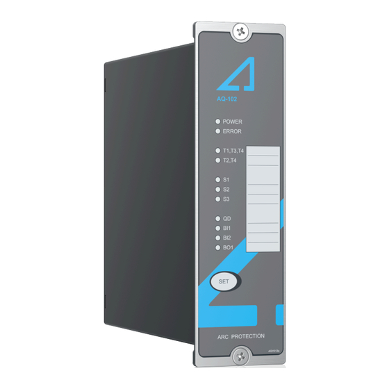
- Page 1 AQ-102 Arc flash protection device Instruction manual...
-
Page 3: Table Of Contents
A A Q Q -102 -102 Instruction manual Version: 2.02 Table of contents 1 Document inf 1 Document informa ormation tion ..............................................5 5 2 Abbr bbre e via viations tions ....................................................7 7 3 General 3 General........................................................ - Page 4 A A Q Q -102 -102 Instruction manual Version: 2.02 14.10 Voltage tests........................38 14.11 Mechanical tests......................38 14.12 Environmental conditions ....................38 14.13 Casing..........................38 15 Or 15 Ordering inf dering informa ormation tion ..............................................39 16 Contact and r 16 Contact and re e f f er erence inf ence informa ormation...
- Page 5 A A Q Q -102 -102 Instruction manual Version: 2.02 Disclaimer Please read these instructions carefully before using the equipment or taking any other actions with respect to the equipment. Only trained and qualified persons are allowed to perform installation, operation, service or maintenance of the equipment.
- Page 6 A A Q Q -102 -102 Instruction manual Version: 2.02 Copyright Copyright © Arcteq Relays Ltd. 2023. All rights reserved. © Arcteq Relays Ltd IM00008...
-
Page 7: Document Inf
A A Q Q -102 -102 Instruction manual Version: 2.02 1 Document information Table. 1 - 1. History of Revision 1. R R e e vision vision 1.00 1.00 Date October 2011 Changes - The first revision of the manual. R R e e vision vision 1.01... - Page 8 A A Q Q -102 -102 Instruction manual Version: 2.02 - Updated the Arcteq logo on the cover. - Updated the distance between the flash and the sensor in the "Testing the operation time" chapter. - Unified terminology used througout the manual (e.g. unit and device means the same thing. Now all AQ 100 series relays are called "devices").
-
Page 9: Abbr Bbre E Via Viations Tions
A A Q Q -102 -102 Instruction manual Version: 2.02 2 Abbreviations AQD – arc quenching device BI – binary input BO – binary output CB – circuit breaker CBFP – circuit breaker failure protection CT – current transformer EPROM – erasable, programmable read-only memory HSO –... -
Page 10: General
A A Q Q -102 -102 Instruction manual Version: 2.02 3 General The AQ-102 is a sophisticated microprocessor-based arc flash protection device with fiber loops sensor channels. The device is designed to minimize the damage caused by an arc fault. This is done by tripping the circuit breaker which supplies current to the fault when fiber loops detect arc light. - Page 11 A A Q Q -102 -102 Instruction manual Version: 2.02 4 Device features AQ-102 is an arc flash protection device which can be applied to a variety of applications. It can be used on its own as a stand-alone device, or it can be a part of a more complex arc protection system by using binary inputs and outputs to connect multiple AQ 100 series devices together.
-
Page 12: Connections
A A Q Q -102 -102 Instruction manual Version: 2.02 5 Connections The figure below depicts the connections of AQ-102. Please note that the SF relay is in the de- energized position. Figure. 5 - 2. Rear terminals of AQ-102. 5.1 Simplified block diagram The figure below presents the main components of the AQ-102 device. - Page 13 A A Q Q -102 -102 Instruction manual Version: 2.02 Figure. 5.1 - 3. Simplified block diagram of AQ-102. © Arcteq Relays Ltd IM00008...
-
Page 14: Inputs
A A Q Q -102 -102 Instruction manual Version: 2.02 5.2 Inputs 5.2.1 Arc sensor channels Figure. 5.2.1 - 4. Arc fiber loop sensor connections AQ-102 has three (3) fiber loop sensor channels: S1, S2 and S3. Each channel has a transmitter (Tx) terminal and a receiver (Rx) terminal. -
Page 15: Outputs
A A Q Q -102 -102 Instruction manual Version: 2.02 Please note that when this device receives an overcurrent signal from a non-AQ 100 series device, the actual operating time depends on the operating time of the that device. Therefore, the total operating time cannot be specified in the technical data. -
Page 16: System Failure Relay
A A Q Q -102 -102 Instruction manual Version: 2.02 This device has four (4) normally open trip relay outputs. Trip relays T1 and T2 are used for tripping circuit breakers. T4 is generally used for tripping one additional disconnecting device, or as a trip alarm (local or remote) monitoring and alarming system. -
Page 17: Arc Sensors C Sensors
A A Q Q -102 -102 Instruction manual Version: 2.02 6 Arc sensors The AQ 100 series provides arc light point sensors and arc light fiber optic loop sensors. These sensors can be used with different devices and different switchgear types according to specific application requirements. -
Page 18: Connecting Sensors
A A Q Q -102 -102 Instruction manual Version: 2.02 Table. 6.4 - 3. Sensor dependencies. P P oint sensors oint sensors F F iber loops iber loops (A (AQ Q -01 & A -01 & AQ Q -02) -02) (A (AQ Q -06, A -06, AQ Q -07 &... - Page 19 A A Q Q -102 -102 Instruction manual Version: 2.02 3. Run the sensor cable through the holes and along the protected area. Fasten it to the compartment walls with cable clips or some other appropriate anchoring method. 4. Turn the black and blue receiver (“Rx”) and transceiver (“Tx”) screws counter-clockwise and plug in the sensor cable terminals.
-
Page 20: Operation And Config Tion And Configura Uration Tion
A A Q Q -102 -102 Instruction manual Version: 2.02 7 Operation and configuration 7.1 DIP switch settings The DIP switches are used to easily configure various tripping logics and other functionalities for the device. The DIP switches are located at the back of the device. The figure below presents the DIP switch numbering, and the table below that gives a detailed description of the settings. -
Page 21: Scheme Selection
A A Q Q -102 -102 Instruction manual Version: 2.02 7.1.1 Scheme selection This chapter describes the schemes that are available to this device. The schemes are configured using the DIP switches numbered 1…4 ("Scheme selection"). The scheme selection is based on binary arithmetic: •... - Page 22 A A Q Q -102 -102 Instruction manual Version: 2.02 Figure. 7.1.2 - 13. Simplified logic diagram of SS:0. SS:1 The logic scheme SS:1 is mainly used in selective arc protection solutions. The fiber sensor S1 monitors the outgoing feeder cable compartment. The fiber sensor S2 monitors the corresponding feeder breaker compartment as well as the busbar compartment.
-
Page 23: Push Button (Set)
A A Q Q -102 -102 Instruction manual Version: 2.02 Figure. 7.1.2 - 15. Simplified logic diagram of SS:1. 7.2 Push button (SET) The device contains one push button, SET SET, and it can be used for all operational functions. The push button is used for: 1. -
Page 24: System Setup (Auto-Configuration)
A A Q Q -102 -102 Instruction manual Version: 2.02 7.2.1 System setup (auto-configuration) After DIP switches have been set to correct position and all sensors, binary inputs and binary outputs have been connected, a system setup procedure (also known as auto-configuration) must be performed. -
Page 25: Led Operations Guide
A A Q Q -102 -102 Instruction manual Version: 2.02 If there is a loose sensor wire or if the self-supervision function detects a configuration mismatch (that is, a new sensor has been attached but the auto-configuration system setup has not been run), the corresponding LED starts flashing and the "Error"... - Page 26 A A Q Q -102 -102 Instruction manual Version: 2.02 The non-volatile memory does not require a power supply to maintain the information and it retains the settings and the indications permanently without power. © Arcteq Relays Ltd IM00008...
-
Page 27: Sy Y St Stem Self-Super 8 S Em Self-Supervision Vision
A A Q Q -102 -102 Instruction manual Version: 2.02 8 System self-supervision AQ 100 series devices have an extensive self-supervision function, including both internal functions and external connections. The self-supervision function monitors the following: • power supply • hardware •... -
Page 28: Applica A Tion Examples
A A Q Q -102 -102 Instruction manual Version: 2.02 9 Application examples This device can be applied to a variety of power switchgear and controlgear layouts and technologies. This chapter describes some of the most typical applications. Please consult the AQ-SAS™ booklet (can be found at arcteq.fi/downloads/) or your nearest Arcteq representative for a solution to your particular application. - Page 29 A A Q Q -102 -102 Instruction manual Version: 2.02 Figure. 9.1 - 17. Connections of the I> and L> application for AQ-102. © Arcteq Relays Ltd IM00008...
- Page 30 A A Q Q -102 -102 Instruction manual Version: 2.02 10 Wiring example Figure. 10 - 18. Example wiring diagram for AQ-102. © Arcteq Relays Ltd IM00008...
-
Page 31: Dimensions And Installa Imensions And Installation Tion
A A Q Q -102 -102 Instruction manual Version: 2.02 11 Dimensions and installation AQ-102 can be either door-mounted or panel-mounted in a standard 19 inch rack. The device's dimensions (without PCBs) are as follows: • Height: 157 mm (6.18 in) •... - Page 32 A A Q Q -102 -102 Instruction manual Version: 2.02 The following image illustrates how a device is installed into a cut-out. Please note that as AQ-102 is narrower than the device in the image, they are connected to the cut-out panel by a single screw on both the top and the bottom of the front panel instead of the two depicted below.
-
Page 33: Testing Esting
A A Q Q -102 -102 Instruction manual Version: 2.02 12 Testing It is recommended that the device is tested prior to substation energizing. Testing is carried out by simulating an arc light for each sensor and verifying that the correct trip contact(s) tripped and that the correct indicator LED(s) turned on. -
Page 34: Testing The Cbfp Function
A A Q Q -102 -102 Instruction manual Version: 2.02 13. If you are using a binary input as the master trip, activate it and verify that the trip has occurred by repeating the steps 5 and 6. 14. Press the SET SET push button to reset all indications and latches. - Page 35 A A Q Q -102 -102 Instruction manual Version: 2.02 © Arcteq Relays Ltd IM00008...
-
Page 36: Tr R Oubleshoo 13 T Oubleshooting Ting
A A Q Q -102 -102 Instruction manual Version: 2.02 13 Troubleshooting Table. 13 - 6. Troubleshooting guide for AQ-102. P P r r oblem oblem P P ossible sol ossible solution( ution(s) s) Check the sensor connection. or or The sensor does not activate during testing. -
Page 37: Technic Echnical Da Al Data Ta
A A Q Q -102 -102 Instruction manual Version: 2.02 14 Technical data 14.1 Mounting and installation Table. 14.1 - 7. Technical data for relay mounting and installation. Panel: - material metal - thickness (min...max) 1.0...5.0 mm (0.04...0.20 in) Panel mounting: - screw type ISO 14581 M4x12, galvanized - key size... -
Page 38: Trip Relays
A A Q Q -102 -102 Instruction manual Version: 2.02 Table. 14.4 - 10. Technical data for the binary inputs (BI1, BI2). Nominal threshold voltage 24 V DC or or 110 V DC or or 220 V DC Threshold: - pick-up Approximately 16 V DC or or 88 V DC or or 178 V DC - drip-off Approximately 15 V DC or or 75 V DC or or 155 V DC... -
Page 39: Fiber Optic Loop Sensors
A A Q Q -102 -102 Instruction manual Version: 2.02 14.8 Fiber optic loop sensors AQ-06 fiber optic loop sensor Table. 14.8 - 14. Technical data for the AQ-06 fiber optic loop sensor. Material Plastic fiber Light intensity threshold 8,000 lux Cable length (min…max) 3…40 m Cable diameter... - Page 40 A A Q Q -102 -102 Instruction manual Version: 2.02 Electrostatic discharge immunity Air discharge: 15 kV (IEC 244-222 and EN 61000-4-2, level 4) Contact discharge: 8 kV Electrical fast transients Power supply input: 4 kV, 5/50 ns (EN 61000-4-4, class III & IEC 801-4, level 4) Other inputs and outputs: 4 kV, 5/50 ns Surge immunity Between wires: 2 kV, 1.2/50 µs...
- Page 41 A A Q Q -102 -102 Instruction manual Version: 2.02 15 Ordering information AQ-102 fiber optic loop sensor device AQ-0x fiber optic loop sensors © Arcteq Relays Ltd IM00008...
- Page 42 A A Q Q -102 -102 Instruction manual Version: 2.02 Accessories Order code Description Note Manufacturer AQX006 Wall mounting bracket For AQ-103 and AQ-110x variants (MV and LV). Arcteq Ltd. AQX016 Wall mounting bracket For AQ-101, AQ-101S and AQ-102 devices (MV and LV). Arcteq Ltd.
- Page 43 A A Q Q -102 -102 Instruction manual Version: 2.02 16 Contact and reference information Manufacturer Arcteq Relays Ltd. Visiting and postal address Kvartsikatu 2 A 1 65300 Vaasa, Finland Contacts Phone: +358 10 3221 370 Website: arcteq.fi Technical support: support.arcteq.fi +358 10 3221 388 (EET 9:00 –...
Need help?
Do you have a question about the ARCTEQ AQ 100 Series and is the answer not in the manual?
Questions and answers