Table of Contents
Advertisement
Quick Links
Advertisement
Table of Contents
Troubleshooting

Related Manuals for ensto ARCTEQ AQ-F255B


Summary of Contents for ensto ARCTEQ AQ-F255B
- Page 1 AQ-F255 Feeder protection device Instruction manual...
-
Page 2: Table Of Contents
A A Q Q -F255 -F255 Instruction manual Version: 2.14 Table of contents 1 1 Document inf Document informa ormation tion ..............................................6 6 1.1 Version 2 revision notes ......................6 1.2 Version 1 revision notes ....................... 10 1.3 Safety information ........................ 11 1.4 Abbreviations........................ - Page 3 A A Q Q -F255 -F255 Instruction manual Version: 2.14 4.5.2 Automatic voltage regulator (90)................299 4.5.3 Parallel voltage regulator..................329 4.5.4 Setting group selection .................... 337 4.5.5 Object control and monitoring.................. 345 4.5.6 Single-pole object control and monitoring ..............357 4.5.7 Indicator object monitoring ..................
- Page 4 A A Q Q -F255 -F255 Instruction manual Version: 2.14 7.2 CPU module ........................548 7.3 Current measurement module ................... 551 7.4 Voltage measurement module.................... 552 7.5 Option cards........................553 7.5.1 Digital input module (optional).................. 553 7.5.2 Digital output module (optional) ................556 7.5.3 High-speed and high-current output module (optional)..........
- Page 5 A A Q Q -F255 -F255 Instruction manual Version: 2.14 8.2.1.10 Overvoltage protection (U>; 59) ............... 599 8.2.1.11 Undervoltage protection (U<; 27) ............. 599 8.2.1.12 Neutral overvoltage protection (U0>; 59N)..........601 8.2.1.13 Sequence voltage protection (U1/U2>/<; 47/27P/59NP) ......601 8.2.1.14 Overfrequency and underfrequency protection (f>/<; 81O/81U)....602 8.2.1.15 Rate-of-change of frequency protection (df/dt>/<;...
- Page 6 A A Q Q -F255 -F255 Instruction manual Version: 2.14 Disclaimer Please read these instructions carefully before using the equipment or taking any other actions with respect to the equipment. Only trained and qualified persons are allowed to perform installation, operation, service or maintenance of the equipment.
-
Page 7: 1 Document Inf Document Informa Ormation Tion
A A Q Q -F255 -F255 1 Document information Instruction manual Version: 2.14 1 Document information 1.1 Version 2 revision notes Table. 1.1 - 1. Version 2 revision notes Revision 2.00 Date 6.6.2019 - New more consistent look. - Improved descriptions generally in many chapters. - Improved readability of a lot of drawings and images. - Page 8 A A Q Q -F255 -F255 1 Document information Instruction manual Version: 2.14 - Terminology consistency improved (e.g. binary inputs are now always called digital inputs). - Tech data modified to be more informative about what type of measurement inputs are used (phase currents/voltages, residual currents/voltages), what component of that measurement is available (RMS, TRMS, peak-to-peak) and possible calculated measurement values (powers, impedances, angles etc.).
- Page 9 A A Q Q -F255 -F255 1 Document information Instruction manual Version: 2.14 - Fixed phase current measurement continuous thermal withstand from 30A to 20A. - Fixed lots of timing errors written to registers table. "Prefault" is -200 ms from Start event, Changes "Pretrigger"...
- Page 10 A A Q Q -F255 -F255 1 Document information Instruction manual Version: 2.14 - Added stage forcing parameter to function descriptions. - Fixes to "Real time signals to comm" description. - Added "Ethernet port" parameter description to IEC61850, IEC104 Modbus TCP descriptions.
-
Page 11: Version 1 Revision Notes
A A Q Q -F255 -F255 1 Document information Instruction manual Version: 2.14 Revision 2.14 Date June 2025 - Increased phase current measurement range. See current measurement technical data chapter. - Fixed inverse time delay formula in Automatic voltage regulator description. -
Page 12: Safety Information
A A Q Q -F255 -F255 1 Document information Instruction manual Version: 2.14 • Added the mA output option card description and updated the order code. Changes • Added the HMI display technical data. 1.3 Safety information This document contains important instructions that should be saved for future use. Read the document carefully before installing, operating, servicing, or maintaining this equipment. -
Page 13: Abbreviations
A A Q Q -F255 -F255 1 Document information Instruction manual Version: 2.14 1.4 Abbreviations AI – Analog input AR – Auto-recloser ASDU – Application service data unit AVR – Automatic voltage regulator BCD – Binary-coded decimal CB – Circuit breaker CBFP –... - Page 14 A A Q Q -F255 -F255 1 Document information Instruction manual Version: 2.14 I/O – Input and output IRIG-B – Inter-range instruction group, timecode B LCD – Liquid-crystal display LED – Light emitting diode LV – Low voltage NC – Normally closed NO –...
-
Page 15: 2 General General
A A Q Q -F255 -F255 2 General Instruction manual Version: 2.14 2 General The AQ-F255 feeder protection device is a member of the AQ 250 product line. The hardware and software are modular: the hardware modules are assembled and configured according to the application's I/O requirements and the software determines the available functions. -
Page 16: 3 De Device User Int Vice User Interface Erface
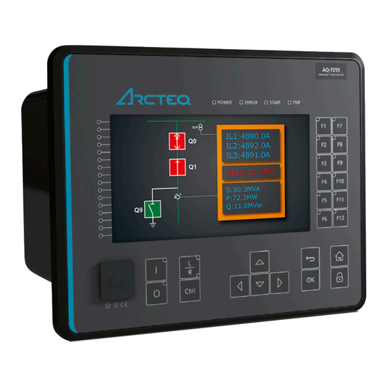
A A Q Q -F255 -F255 3 Device user interface Instruction manual Version: 2.14 3 Device user interface 3.1 Panel structure The user interface section of an AQ 200 or AQ 250 series device is divided into two user interface sections: one for the hardware and the other for the software. - Page 17 A A Q Q -F255 -F255 3 Device user interface Instruction manual Version: 2.14 When the unit is powered on, the green "Power" LED is lit. When the red "Error" LED is lit, the device has an internal (hardware or software) error that affects the operation of the unit. The activation of the yellow "Start"...
-
Page 18: 4 F F Unctions Unctions
A A Q Q -F255 -F255 4 Functions Instruction manual Version: 2.14 4 Functions 4.1 Functions included in AQ-F255 The AQ-F255 feeder protection device includes the following functions as well as the number of stages for those functions. The following function packages are available: •... - Page 19 A A Q Q -F255 -F255 4 Functions Instruction manual Version: 2.14 Name (number of ANSI Description stages) U> Overvoltage protection. U>> OV (4) U>>> Not incl t included in function packa uded in function package "B". ge "B". U>>>> U<...
- Page 20 A A Q Q -F255 -F255 4 Functions Instruction manual Version: 2.14 Name (number of ANSI Description stages) P, Q, S>/< P, Q, S>>/<< Power protection. P, Q, PQS (4) S>>>/<<< Not incl t included in function packa uded in function package "B". ge "B".
-
Page 21: Measurements
A A Q Q -F255 -F255 4 Functions Instruction manual Version: 2.14 Name ANSI Description Vector jump. ∆φ Not incl t included in function packa uded in function package "B". ge "B". 0 → 1 Auto-recloser. Automatic voltage regulator (independet or parallel). Incl Included in function packa uded in function package "V". - Page 22 A A Q Q -F255 -F255 4 Functions Instruction manual Version: 2.14 Figure. 4.2.1 - 2. Current measurement terminology. P P RI: RI: The primary current, i.e. the current which flows in the primary circuit and through the primary side of the current transformer.
- Page 23 A A Q Q -F255 -F255 4 Functions Instruction manual Version: 2.14 The device calculates the scaling factors based on the set values of the CT primary, the CT secondary and the nominal current settings. The device measures the secondary current, the current output from the current transformer installed into application's primary circuit.
- Page 24 A A Q Q -F255 -F255 4 Functions Instruction manual Version: 2.14 • The phase currents are connected to the I01 residual via a Holmgren connection. • The starpoint of the phase current CT's secondary current is towards the line. Phase CT scaling Next, to scale the current to per-unit values, we have to select whether the basis of the phase CT scaling is the protected object's nominal current or the CT primary value.
- Page 25 A A Q Q -F255 -F255 4 Functions Instruction manual Version: 2.14 Once the measurement scaling is tied to the protected object's nominal current, the user must set the appropriate input for the "Nominal current In" setting. One can now see the differences between the two scaling options (CT nominal vs.
- Page 26 A A Q Q -F255 -F255 4 Functions Instruction manual Version: 2.14 Figure. 4.2.1 - 8. Scalings display (based on the CT nominal). Figure. 4.2.1 - 9. Scalings display (based on the protected object's nominal current). As the images above show, the scaling selection does not affect how primary and secondary currents are displayed (as actual values).
-
Page 27: Troubleshooting
A A Q Q -F255 -F255 4 Functions Instruction manual Version: 2.14 Figure. 4.2.1 - 10. Connections of ZCT scaling. Troubleshooting When the measured current values differ from the expected current values, the following table offers possible solutions for the problems. W W ARNING! ARNING! If you work with energized CTs, extreme caution needs to be taken when checking the... - Page 28 A A Q Q -F255 -F255 4 Functions Instruction manual Version: 2.14 Problem Solution The phase currents are connected to the measurement module but the order or polarity of one or all phases is incorrect. In device settings, go to Measurement → Phasors and check the "Phase current vectors"...
- Page 29 A A Q Q -F255 -F255 4 Functions Instruction manual Version: 2.14 Figure. 4.2.1 - 11. Common phase polarity problems. The following image presents the most common problems with network rotation (mix phases). These problems can be difficult to find because the measurement result is always the same in the device. If two phases are mixed together, the network rotation always follows the pattern IL1-IL3-IL2 and the measured negative sequence current is therefore always 1.00 (in.
- Page 30 A A Q Q -F255 -F255 4 Functions Instruction manual Version: 2.14 Figure. 4.2.1 - 12. Common network rotation (mixed phases) problems. Settings Table. 4.2.1 - 7. Settings of the Phase CT scaling. Name Range Step Default Description Scale • CT nom p.u. •...
- Page 31 A A Q Q -F255 -F255 4 Functions Instruction manual Version: 2.14 Name Range Step Default Description A feedback value; the calculated scaling factor that is the ratio between the set primary current and the set CT scaling nominal current. This parameter is only visible if the factor NOM option "Object In p.u."...
- Page 32 A A Q Q -F255 -F255 4 Functions Instruction manual Version: 2.14 Table. 4.2.1 - 10. Per-unit phase current measurements. Name Unit Range Step Description 0.000…1 The current fundamental frequency component (in p.u.) from each Pha.curr.ILx × In 0.001 250.000 of the phase current channels.
- Page 33 A A Q Q -F255 -F255 4 Functions Instruction manual Version: 2.14 Table. 4.2.1 - 15. Primary residual current measurements. Name Unit Range Step Description 0.00…1 The primary current measurement fundamental frequency Pri.Res.curr.I0x 0.01 component from the residual current channel I01 or I02. 000.00 0.00…1 The primary current measurement fundamental frequency...
- Page 34 A A Q Q -F255 -F255 4 Functions Instruction manual Version: 2.14 Table. 4.2.1 - 19. Primary sequence current measurements. Name Unit Range Step Description Pri.Positive 0.00…1 000 The primary measurement from the calculated positive 0.01 sequence curr. 000.00 sequence current. Pri.Negative 0.00…1 000 The primary measurement from the calculated negative...
- Page 35 A A Q Q -F255 -F255 4 Functions Instruction manual Version: 2.14 Name Range Step Description Ixx Amplitude % 0.000...100.000 0.001 Amplitude ratio THD voltage. Recognized by IEC. Ixx Power THD % 0.000...100.000 0.001 Power ratio THD voltage. Recognized by the IEEE. Current component measurements The current component measurements indicate the resistive (wattmetric cos[φ]) and reactive (varmetric sin[φ]) current values.
-
Page 36: Voltage Measurement And Scaling
A A Q Q -F255 -F255 4 Functions Instruction manual Version: 2.14 Name Unit Range Step Description ILx Reactive –100 000.00 The primary reactive current component measurement 0.01 Current Pri. …100 000.00 from each of the phase current channels. Pos.Seq. Resistive –100 000.00 The primary resistive current component measurement 0.01... - Page 37 A A Q Q -F255 -F255 4 Functions Instruction manual Version: 2.14 Figure. 4.2.2 - 13. Voltage measurement terminology P P RI: RI: The primary voltage, i.e. the voltage in the primary circuit which is connected to the primary side of the voltage transformer.
- Page 38 A A Q Q -F255 -F255 4 Functions Instruction manual Version: 2.14 Figure. 4.2.2 - 14. Connections. The following table presents the initial data of the connection. Table. 4.2.2 - 26. Initial data. P P ha hase v se volta oltage V ge VT T Z Z er ero sequence v...
- Page 39 A A Q Q -F255 -F255 4 Functions Instruction manual Version: 2.14 Figure. 4.2.2 - 15. Example connections for voltage line-to-line measurement. If only two line-to-line voltages are measured, the third one (U ) is calculated based on the U vectors.
- Page 40 A A Q Q -F255 -F255 4 Functions Instruction manual Version: 2.14 Figure. 4.2.2 - 16. 2LL+U0+SS settings and connections. The image collection below presents the device's behavior when nominal voltage is injected into the device via secondary test equipment. The measurement mode is 3LN+U4 which means that the device is measuring line-to-neutral voltages.
-
Page 41: Troubleshooting
A A Q Q -F255 -F255 4 Functions Instruction manual Version: 2.14 Figure. 4.2.2 - 18. Device behavior when voltage injected during an earth fault. Troubleshooting When the measured voltage values differ from the expected voltage values, the following table offers possible solutions for the problems. - Page 42 A A Q Q -F255 -F255 4 Functions Instruction manual Version: 2.14 Alternative Settings Table. 4.2.2 - 27. Settings of the VT scaling. Name Range Step Default Description Voltage • 3LN+U4 The device's voltage wiring method. The voltages are measurement •...
- Page 43 A A Q Q -F255 -F255 4 Functions Instruction manual Version: 2.14 Name Range Step Default Description Voltage • Disabled Activates the voltage memory. The "Voltage memory" Disabled memory • Activated chapter describes the function in more detail. • No P-E voltages available Indicates whether or not phase-to-earth voltages are...
- Page 44 A A Q Q -F255 -F255 4 Functions Instruction manual Version: 2.14 Table. 4.2.2 - 28. Read-only parameters of the VT scaling. Name Description VT scaling factor The calculated scaling factor that is the ratio between the primary voltage and the secondary voltage.
- Page 45 A A Q Q -F255 -F255 4 Functions Instruction manual Version: 2.14 Table. 4.2.2 - 31. Voltage phase angle measurements. Name Range Step Description Ux Angle 0.00…360.00° 0.01° The phase angle measurement from each of the four voltage inputs. Table. 4.2.2 - 32. Per-unit sequence voltage measurements. Name Range Step...
- Page 46 A A Q Q -F255 -F255 4 Functions Instruction manual Version: 2.14 Table. 4.2.2 - 36. System primary voltage measurements. Name Range Step Description System 0.00…1 volt The primary line-to-line UL12 voltage fundamental frequency component 0.01V UL12 (measured or calculated). You can also select the row where the unit for this is kV. 000.00V System 0.00…1...
- Page 47 A A Q Q -F255 -F255 4 Functions Instruction manual Version: 2.14 Name Range Step Description System volt UL31 0.00…360.00° 0.01° The primary line-to-line angle UL23 (measured or calculated). System volt UL1 0.00…360.00° 0.01° The primary line-to-neutral angle UL1 (measured or calculated). System volt UL2 0.00…360.00°...
- Page 48 A A Q Q -F255 -F255 4 Functions Instruction manual Version: 2.14 Voltage memory Some protection functions (such as directional overcurrent) use the device's measured current and voltage to determine whether the electrical network fault appears to be inside the protected area. The determination is made by comparing the angle between the operating quantity (zone/tripping area) and the actual measured quantity.
- Page 49 A A Q Q -F255 -F255 4 Functions Instruction manual Version: 2.14 While voltage memory is active, voltages are absent and therefore angle measurement is not possible. Healthy state angles (before a fault) are used during a fault. This is why a drift between the assumed voltage angle and the actual measured phase current angle takes place.
- Page 50 A A Q Q -F255 -F255 4 Functions Instruction manual Version: 2.14 When the "Forced CT f tracking" parameter is activated and voltages are gone, the frequency from the selected current-based reference channel 3 (the current from IL3) is used for current sampling. This eliminates any possible measurement errors in the fixed frequency mode.
-
Page 51: Power And Energy Calculation
A A Q Q -F255 -F255 4 Functions Instruction manual Version: 2.14 Event block name Event names M1VT1 Frequency tracked from CT ON M1VT1 Frequency tracked from CT OFF M1VT1 Using Voltage memory ON M1VT1 Using Voltage memory OFF M1VT1 Voltage memory blocked ON M1VT1 Voltage memory blocked OFF... - Page 52 A A Q Q -F255 -F255 4 Functions Instruction manual Version: 2.14 Figure. 4.2.3 - 23. Three-phase reactive power (Q) calculation. Active power can be to the forward or the reverse direction. The direction of active power can be indicated with the power factor (Cos (φ), or Cosine phi), which is calculated according the following formula: The direction of reactive power is divided into four quadrants.
- Page 53 A A Q Q -F255 -F255 4 Functions Instruction manual Version: 2.14 If the line-to-line voltages are measured but the zero sequence voltage is not measured or is not otherwise known, the three-phase power calculation is based on Aron’s theorem: Both cos(φ) and tan(φ) are calculated in the same way as in the line-to-neutral mode.
- Page 54 A A Q Q -F255 -F255 4 Functions Instruction manual Version: 2.14 Name Range Step Default Description • Undefined • Q1 Fwd Cap AV Indicates what the power VA quadrant is at VA Quadrant • Q2 Rev Ind AV Undefined that moment.
-
Page 55: Power Measurements
A A Q Q -F255 -F255 4 Functions Instruction manual Version: 2.14 Name Range Step Default Description • 3PH.Fwd.Act.EP Selects whether the energy is active DC 1…4 • 3PH.Rev.Avt.EP or reactive, whether the direction of Input • 3PH.Fwd.React.EQ.CAP 3PH.Fwd.Act.EP the energy is forward of reverse, and signal •... -
Page 56: Energy Measurements
A A Q Q -F255 -F255 4 Functions Instruction manual Version: 2.14 Name Range Step Description 3PH Power factor 0.0001 The three-phase power factor -1x10 …1x10 Table. 4.2.3 - 45. Single-phase power calculations (L1...L3). Name Unit Range Step Description Lx Apparent power (S) kVA 0.001 The apparent power of Phase Lx in kilo-volt-amperes -1x10... - Page 57 A A Q Q -F255 -F255 4 Functions Instruction manual Version: 2.14 Name Range Step Description Apparent Energy (S) while Export The total amount of exported apparent energy -1x10 …1x10 (P) (kVAh or MVAh) while active energy is exported. Apparent Energy (S) while Import The total amount of exported apparent energy -1x10 …1x10...
-
Page 58: Calculation Examples
A A Q Q -F255 -F255 4 Functions Instruction manual Version: 2.14 Name Range Step Description Apparent Energy (S) while Import The apparent energy of the phase while active -1x10 …1x10 (P) Lx energy is imported. Calculation examples Here is an example of power calculation. Both wiring methods (line-to-line and line-to-neutral) are checked with the same signal injection. -
Page 59: Frequency Tracking And Scaling
A A Q Q -F255 -F255 4 Functions Instruction manual Version: 2.14 Voltages (line-to-line): Currents: = 100.00 V, -90.00° = 2.5 A, -120.00° = 2.5 A, 120.00° Name Values 3PH (S) 20.00 MVA 3PH (P) 17.32 MW 3PH (Q) 0.00 Mvar 3PH Tan 0.00 3PH Cos... - Page 60 A A Q Q -F255 -F255 4 Functions Instruction manual Version: 2.14 Table. 4.2.4 - 48. Frequency tracking effect (FF changes from 6 Hz to 75 Hz). The measurement error with a fixed 50 Hz sampling The measurement error with frequency tracking frequency when the frequency changes.
- Page 61 A A Q Q -F255 -F255 4 Functions Instruction manual Version: 2.14 Settings Table. 4.2.4 - 49. Settings of the frequency tracking. Name Range Step Default Description Defines which measurement sampling mode is in Sampling • Fixed Fixed use: the fixed user-defined frequency, or the mode •...
- Page 62 A A Q Q -F255 -F255 4 Functions Instruction manual Version: 2.14 Name Range Step Default Description • Start tracking Defines the how the tracking starts. Tracking can Start immediately start immediately, or there can be a set delay time Start behavior tracking •...
-
Page 63: General Menu
A A Q Q -F255 -F255 4 Functions Instruction manual Version: 2.14 Name Range Step Default Description • Not SS1f measurable Displays which voltage channel frequency meas.from • Fast Ref U3 reference is used by "system set" voltage channel. • Fast Ref U4 •... - Page 64 A A Q Q -F255 -F255 4 Functions Instruction manual Version: 2.14 Name Range Default Description Allow local modes to be modified from setting tool, HMI and IEC61850. • Prohibited Prohibited: Cannot be changed. Allow setting • From HMI/ of individual setting tool Prohibited From HMI/setting tool only: Can only be changed from the...
-
Page 65: Protection Functions
A A Q Q -F255 -F255 4 Functions Instruction manual Version: 2.14 Name Range Default Description Resets the latched signals in the logic and the matrix. When a • - Reset latches reset command is given, the parameter automatically returns •... - Page 66 A A Q Q -F255 -F255 4 Functions Instruction manual Version: 2.14 The protection function is run in a completely digital environment with a protection CPU microprocessor which also processes the analog signals transformed into the digital form. © Arcteq Relays Ltd IM00015...
- Page 67 A A Q Q -F255 -F255 4 Functions Instruction manual Version: 2.14 Figure. 4.4.1 - 24. Principle diagram of the protection device platform. In the following chapters the common functionalities of protection functions are described. If a protection function deviates from this basic structure, the difference is described in the corresponding chapter of the manual.
-
Page 68: Function Blocking
A A Q Q -F255 -F255 4 Functions Instruction manual Version: 2.14 Figure. 4.4.1 - 26. Measurement range in relation to the nominal current. The I magnitude refers to the user set nominal current which can range from 0.2…10 A, typically 0.2 A, 1A or 5 A. - Page 69 A A Q Q -F255 -F255 4 Functions Instruction manual Version: 2.14 Figure. 4.4.1 - 27. Operating time delay: Definite (minimum) operating time delay and the minimum for tripping. Table. 4.4.1 - 53. Operating time characteristics setting parameters (general). Name Range Step Default...
- Page 70 A A Q Q -F255 -F255 4 Functions Instruction manual Version: 2.14 Name Range Step Default Description Selects the IEC standard delay characteristics. The options include the following: Normally Inverse ("NI"), Extremely Inverse ("EI"), Very Inverse ("VI") and • NI Long Time Inverse ("LTI") characteristics.
- Page 71 A A Q Q -F255 -F255 4 Functions Instruction manual Version: 2.14 Figure. 4.4.1 - 28. Inverse definite minimum time formulas for IEC and IEEE standards. Non-standard delay characteristics In addition to the previously mentioned delay characteristics, some functions also have delay characteristics that deviate from the IEC or IEEE standards.
- Page 72 A A Q Q -F255 -F255 4 Functions Instruction manual Version: 2.14 NOTICE! TICE! When using RD-type and "k" has been set lower than 0.3 calculated operation time can be lower than 0 seconds with some measurement values. In these cases operation time will be instant.
- Page 73 A A Q Q -F255 -F255 4 Functions Instruction manual Version: 2.14 Figure. 4.4.1 - 29. No delayed pick-up release. Figure. 4.4.1 - 30. Delayed pick-up release, delay counter is reset at signal drop-off. © Arcteq Relays Ltd IM00015...
- Page 74 A A Q Q -F255 -F255 4 Functions Instruction manual Version: 2.14 Figure. 4.4.1 - 31. Delayed pick-up release, delay counter value is held during the release time. Figure. 4.4.1 - 32. Delayed pick-up release, delay counter value is decreasing during the release time. ©...
-
Page 75: Non-Directional Overcurrent Protection (I>; 50/51)
A A Q Q -F255 -F255 4 Functions Instruction manual Version: 2.14 Stage forcing It is possible to test the logic, event processing and the operation of the device's logic by controlling the state of the protection functions manually without injecting any current into the device with stage forcing. -
Page 76: General Settings
A A Q Q -F255 -F255 4 Functions Instruction manual Version: 2.14 Signal Description TRMS TRMS measurement of phase L2 (B) current TRMS TRMS measurement of phase L3 (C) current Peak-to-peak measurement of phase L1 (A) current Peak-to-peak measurement of phase L2 (B) current Peak-to-peak measurement of phase L3 (C) current General settings The following general settings define the general behavior of the function. -
Page 77: Pick-Up Settings
A A Q Q -F255 -F255 4 Functions Instruction manual Version: 2.14 Pick-up settings The I setting parameter controls the pick-up of the I> function. This defines the maximum allowed measured current before action from the function. The function constantly calculates the ratio between the I and the measured magnitude ( I ) for each of the three phases. - Page 78 A A Q Q -F255 -F255 4 Functions Instruction manual Version: 2.14 Name Range Step Description Displays the expected operating time when a fault occurs. When Expected IDMT mode is used, the expected operating time depends on the operating 0.000...1800.000s 0.005s measured highest phase current value.
- Page 79 A A Q Q -F255 -F255 4 Functions Instruction manual Version: 2.14 Figure. 4.4.2 - 34. Typical operation time delays with different current to setting ratios in instant operation mode. Events and registers The non-directional overcurrent function (abbreviated "NOC" in event block names) generates events and registers from the status changes in the events listed below.
-
Page 80: Single-Pole Non-Directional Overcurrent Protection (I>; 50/51)
A A Q Q -F255 -F255 4 Functions Instruction manual Version: 2.14 Event block name Event names NOC1...NOC4 Phase C Start OFF NOC1...NOC4 Phase A Trip ON NOC1...NOC4 Phase A Trip OFF NOC1...NOC4 Phase B Trip ON NOC1...NOC4 Phase B Trip OFF NOC1...NOC4 Phase C Trip ON NOC1...NOC4... - Page 81 A A Q Q -F255 -F255 4 Functions Instruction manual Version: 2.14 Figure. 4.4.3 - 35. Simplified function block diagram of the I> function. Measured input The function block uses phase current measurement values. The user can select the monitored magnitude to be equal either to RMS values (fundamental frequency component), to TRMS values from the whole harmonic specter of 32 components, or to peak-to-peak values.
- Page 82 A A Q Q -F255 -F255 4 Functions Instruction manual Version: 2.14 Table. 4.4.3 - 64. General settings of the function. Name Range Default Description Setting control • Disabled Activating this parameter allows changing the pick-up level of the Disabled from comm bus •...
- Page 83 A A Q Q -F255 -F255 4 Functions Instruction manual Version: 2.14 Table. 4.4.3 - 66. Information displayed by the function. Name Range Step Description • On Displays the mode of NOC block. • Blocked I> LN • Test This parameter is visible only when Allow setting of individual LN behaviour •...
- Page 84 A A Q Q -F255 -F255 4 Functions Instruction manual Version: 2.14 Name Range Step Default Description harmonic blocking limit Defines the limit of the 2 0.10…50.00%I 0.01%I 0.01%I fund fund fund (Iharm/Ifund) harmonic blocking. If the blocking signal is active when the pick-up element activates, a BLOCKED signal is generated and the function does not process the situation further.
-
Page 85: Non-Directional Earth Fault Protection (I0>; 50N/51N)
A A Q Q -F255 -F255 4 Functions Instruction manual Version: 2.14 Event block name Event names NOCS1 L1 Trip ON NOCS1 L1 Trip OFF NOCS1 L2 Trip ON NOCS1 L2 Trip OFF NOCS1 L3 Trip ON NOCS1 L3 Trip OFF The function registers its operation into the last twelve (12) time-stamped registers;... - Page 86 A A Q Q -F255 -F255 4 Functions Instruction manual Version: 2.14 Figure. 4.4.4 - 36. Simplified function block diagram of the I0> fucntion. Measured input The function block uses residual current measurement values. The available analog measurement channels are I and I (residual current measurement) and I (residual current calculated from...
- Page 87 A A Q Q -F255 -F255 4 Functions Instruction manual Version: 2.14 Table. 4.4.4 - 71. General settings of the function. Name Range Default Description Setting • Disabled Activating this parameter permits changing the pick-up level of the control from Disabled •...
- Page 88 A A Q Q -F255 -F255 4 Functions Instruction manual Version: 2.14 Table. 4.4.4 - 73. Information displayed by the function. Name Range Step Description • On Displays the mode of NEF block. • Blocked I0> LN • Test This parameter is visible only when Allow setting of individual LN behaviour •...
- Page 89 A A Q Q -F255 -F255 4 Functions Instruction manual Version: 2.14 If the blocking signal is active when the pick-up element activates, a BLOCKED signal is generated and the function does not process the situation further. If the START function has been activated before the blocking signal, it resets and processes the release time characteristics similarly to when the pick-up signal is reset.
-
Page 90: Directional Overcurrent Protection (Idir>; 67)
A A Q Q -F255 -F255 4 Functions Instruction manual Version: 2.14 Name Description Fault current Start/Trip current Pre-fault current Start -200ms current Trip time remaining 0 ms...1800s Setting group in use Setting group 1...8 active. 4.4.5 Directional overcurrent protection (Idir>; 67) The directional overcurrent function is used for instant and time-delayed overcurrent and short-circuits. - Page 91 A A Q Q -F255 -F255 4 Functions Instruction manual Version: 2.14 Signal Description Fundamental frequency component of phase L2 (B) current measurement Fundamental frequency component of phase L3 (C) current measurement TRMS TRMS measurement of phase L1 (A) current TRMS TRMS measurement of phase L2 (B) current TRMS...
- Page 92 A A Q Q -F255 -F255 4 Functions Instruction manual Version: 2.14 Pick-up settings The I setting parameter controls the pick-up of the I> function. This defines the maximum allowed measured current before action from the function. The function constantly calculates the ratio between the I and the measured magnitude ( I ) for each of the three phases.
- Page 93 A A Q Q -F255 -F255 4 Functions Instruction manual Version: 2.14 Figure. 4.4.5 - 38. Angle tracking of the Idir> function (3LN/3LL + U mode). Please note in the picture above that the tripping area is linked to the angle of the positive sequence voltage U .
- Page 94 A A Q Q -F255 -F255 4 Functions Instruction manual Version: 2.14 Figure. 4.4.5 - 39. Operation sector area when the sector center has been set to -45 degrees. Figure. 4.4.5 - 40. When Idir> function has been set to "Non-directional" the function works basically just like a traditional non-directional overcurrent protection function.
- Page 95 A A Q Q -F255 -F255 4 Functions Instruction manual Version: 2.14 Read-only parameters The function's Info page displays useful, real-time information on the state of the protection function. It is accessed either through the device's HMI display, or through the setting tool software when it is connected to the device and its Live Edit mode is active.
- Page 96 A A Q Q -F255 -F255 4 Functions Instruction manual Version: 2.14 The variables the user can set are binary signals from the system. The blocking signal needs to reach the device minimum of 5 ms before the set operating delay has passed in order for the blocking to activate in time.
-
Page 97: Directional Earth Fault Protection (I0Dir>; 67N/32N)
A A Q Q -F255 -F255 4 Functions Instruction manual Version: 2.14 Table. 4.4.5 - 83. Register content. Register name Description Date and time dd.mm.yyyy hh:mm:ss.mss Event Event name Fault type L1-E...L1-L2-L3 Pre-trigger current Start/Trip -20ms current Fault current Start/Trip current Pre-fault current Start -200ms averages Trip time remaining... - Page 98 A A Q Q -F255 -F255 4 Functions Instruction manual Version: 2.14 The fault current angle is based on comparing the neutral voltage U angle to the residual current I angle. Both I and U must be above the squelch limit to be able to detect the angle. The squelch limit for the I current is 0.01 x I and for the U...
- Page 99 A A Q Q -F255 -F255 4 Functions Instruction manual Version: 2.14 Name Range Default Description • Select U0> Meas • U0 Defines which available neutral voltage measurement is used. input Calculated Select Available neutral voltages depend on measurement settings ( Measurements →...
- Page 100 A A Q Q -F255 -F255 4 Functions Instruction manual Version: 2.14 Name Range Step Default Description Pick-up setting > Comp. pick-up Voltage pick-up setting. If broadrange mode is setting 1…75%U 0.01%U 20%U selected, unearthed and compensated networks (I0Cosfi)> have separate pick-up settings. Unearth.
- Page 101 A A Q Q -F255 -F255 4 Functions Instruction manual Version: 2.14 Unearthed network Figure. 4.4.6 - 42. Angle tracking of I0dir> function (unearthed network model) (32N) When the unearthed (capacitive) network mode is chosen, the function expects the fault current to be lagging zero sequence voltage by 90 degrees.
- Page 102 A A Q Q -F255 -F255 4 Functions Instruction manual Version: 2.14 The resistance of the fault affects the size of the voltage drop during a fault. In direct earth fault the zero sequence voltage amplitude is equal to the system's line-to-earth voltage. In direct earth fault the voltage of a faulty phase drops close to zero and healthy phase voltages increase to the amplitude of line-to-line voltages.
- Page 103 A A Q Q -F255 -F255 4 Functions Instruction manual Version: 2.14 When the Petersen coil earthed (compensated) network mode is chosen, the function expects the fault current to be in the opposite direction to the zero sequence voltage. Healthy phases of both healthy and faulty feeders produce a capacitive current similar to the unearthed network.
- Page 104 A A Q Q -F255 -F255 4 Functions Instruction manual Version: 2.14 Directly earthed or small impedance network (67N) Figure. 4.4.6 - 44. Angle tracking of I0dir> function (directly earthed or small impedance network). In a directly earthed network the amplitude of a single-phase fault current is similar to the amplitude of a short-circuit current.
- Page 105 A A Q Q -F255 -F255 4 Functions Instruction manual Version: 2.14 Broad range mode with multi-criteria detection for unearthed and compensated networks When detecting earth faults in compensated long-distance cables and overhead lines, it is in some cases difficult to distinguish between a healthy and a faulty feeder. Merely measuring the angle and the magnitude of residual voltage and currents is not always enough, as changes in symmetrical components of phase currents and voltages are also needed.
- Page 106 A A Q Q -F255 -F255 4 Functions Instruction manual Version: 2.14 The new broad range mode is capable of detecting an earth fault directionally in both unearthed and compensated networks not only by combining the two stages together but by using a new multi-criteria detection.
- Page 107 A A Q Q -F255 -F255 4 Functions Instruction manual Version: 2.14 Name Range Step Description • Normal I0dir> • Start Displays the status of the protection function. condition • Trip • Blocked Displays which voltage channel is used by the function. If no voltage channel has been selected the function •...
- Page 108 A A Q Q -F255 -F255 4 Functions Instruction manual Version: 2.14 Table. 4.4.6 - 88. Internal inrush harmonic blocking settings. Name Range Step Default Description Inrush harmonic blocking • No Enables and disables the 2 (internal-only trip) • Yes harmonic blocking.
- Page 109 A A Q Q -F255 -F255 4 Functions Instruction manual Version: 2.14 The function's outputs can be used for direct I/O controlling and user logic programming. The function also provides a cumulative counter for the START, TRIP and BLOCKED events. The function offers four (4) independent stages;...
-
Page 110: Intermittent Earth Fault Protection (I0Int>; 67Nt)
A A Q Q -F255 -F255 4 Functions Instruction manual Version: 2.14 Register Description Fault U Start/Trip voltage (in Volts) fault angle 0...360° Trip time remaining 0 ms...1800s Setting group in use Setting group 1...8 active Network GND Unearthed, Petersen coil earthed, Earthed network pre-fault current Start -200ms current 4.4.7 Intermittent earth fault protection (I0int>;... - Page 111 A A Q Q -F255 -F255 4 Functions Instruction manual Version: 2.14 Figure. 4.4.7 - 47. An intermittent earth fault in a medium size network tuned close to resonance, as seen by a protection relay of a faulty feeder. © Arcteq Relays Ltd IM00015...
- Page 112 A A Q Q -F255 -F255 4 Functions Instruction manual Version: 2.14 Figure. 4.4.7 - 48. An intermittent earth fault in a network tuned close to resonance, as seen by a protection relay of a healthy feeder. © Arcteq Relays Ltd IM00015...
- Page 113 A A Q Q -F255 -F255 4 Functions Instruction manual Version: 2.14 Figure. 4.4.7 - 49. An intermittent earth fault in an undercompensated medium size network, as seen by protection relay of a faulty feeder. © Arcteq Relays Ltd IM00015...
- Page 114 A A Q Q -F255 -F255 4 Functions Instruction manual Version: 2.14 Figure. 4.4.7 - 50. Undercompensated medium size network intermittent earth fault seen by a protection relay of a healthy feeder. As can be seen from the figures above, the residual voltage is high both in the network tuned close to resonance and in the undercompensated network.
- Page 115 A A Q Q -F255 -F255 4 Functions Instruction manual Version: 2.14 More detailed information of the patent can be found on the European Patent Office webpages. The patent's data code is EP3213381 (A1). A link to the patent: https://worldwide.espacenet.com/publicationDetails/ biblio?II=2&ND=3&adjacent=true&locale=en_EP&FT=D&date=20170906&CC=EP&NR=3213381A1&KC=A1.
-
Page 116: General Settings
A A Q Q -F255 -F255 4 Functions Instruction manual Version: 2.14 Setting parameter Value FWD reset time 0.450 s REV reset time 0.450 s Definite operating time delay 0.500 s Spikes to trip > The best verification for the settings is a field test with a test system capable of intermittent earth faults. One network characteristic may vary significantly from another. -
Page 117: Pick-Up Settings
A A Q Q -F255 -F255 4 Functions Instruction manual Version: 2.14 Name Range Default Description • I01 Input selection Defines which measured residual current is used by the function. • I02 Defines the characteristics used by the function: • Protected P P r r o o t t ect ected line IE constant ed line IE constant: Earth fault current magnitude is... - Page 118 A A Q Q -F255 -F255 4 Functions Instruction manual Version: 2.14 Name Range Step Description • Normal • StartFWD I0Int> • StartREV Displays status of the protection function. condition • Trip • Blocked U0> • No U0 avail! Displays which voltage channel is used by the function. If no voltage measuring •...
- Page 119 A A Q Q -F255 -F255 4 Functions Instruction manual Version: 2.14 Name Range Step Default Description The "Absolute FWD spikes to trip" setting sums detected forward spikes. Spike detected in the reverse direction resets the counter and the direction is changed.
- Page 120 A A Q Q -F255 -F255 4 Functions Instruction manual Version: 2.14 Event block name Event names IEF1 Start FWD OFF IEF1 Start REV ON IEF1 Start REV OFF IEF1 Trip ON IEF1 Trip OFF IEF1 Block ON IEF1 Block OFF IEF1 Intermittent EF detected ON IEF1...
-
Page 121: Negative Sequence Overcurrent/ Phase Current Reversal/ Current Unbalance Protection (I2>; 46/46R/46L)
A A Q Q -F255 -F255 4 Functions Instruction manual Version: 2.14 4.4.8 Negative sequence overcurrent/ phase current reversal/ current unbalance protection (I2>; 46/46R/46L) The current unbalance function is used for instant and time-delayed unbalanced network protection and for detecting broken conductors. The number of stages in the function depends on the device model. - Page 122 A A Q Q -F255 -F255 4 Functions Instruction manual Version: 2.14 Signal Description Fundamental frequency component of phase L1 (A) current measurement Fundamental frequency component of phase L2 (B) current measurement Fundamental frequency component of phase L3 (C) current measurement General settings The following general settings define the general behavior of the function.
- Page 123 A A Q Q -F255 -F255 4 Functions Instruction manual Version: 2.14 Read-only parameters The function's Info page displays useful, real-time information on the state of the protection function. It is accessed either through the device's HMI display, or through the setting tool software when it is connected to the device and its Live Edit mode is active.
- Page 124 A A Q Q -F255 -F255 4 Functions Instruction manual Version: 2.14 • t = Operating time • I = Calculated negative sequence 2meas • k = Constant k value (user settable delay multiplier) • I = Pick-up setting of the function Figure.
-
Page 125: Harmonic Overcurrent Protection (Ih>; 50H/51H/68H)
A A Q Q -F255 -F255 4 Functions Instruction manual Version: 2.14 Table. 4.4.8 - 103. Event messages. Event block name Event names CUB1...CUB4 Start ON CUB1...CUB4 Start OFF CUB1...CUB4 Trip ON CUB1...CUB4 Trip OFF CUB1...CUB4 Block ON CUB1...CUB4 Block OFF The function registers its operation into the last twelve (12) time-stamped registers. - Page 126 A A Q Q -F255 -F255 4 Functions Instruction manual Version: 2.14 Figure. 4.4.9 - 53. Simplified function block diagram of the Ih> function. Measured input The function block uses analog current measurement values from phase or residual currents. Each measurement input of the function block uses RMS (fundamental frequency component) values and harmonic components of the selected current input.
- Page 127 A A Q Q -F255 -F255 4 Functions Instruction manual Version: 2.14 Signal Description The magnitudes (RMS) of phase L2 (B) current components: - Fundamental harmonic harmonic harmonic harmonic harmonic harmonic harmonic - 11 harmonic - 13 harmonic - 15 harmonic - 17 harmonic...
- Page 128 A A Q Q -F255 -F255 4 Functions Instruction manual Version: 2.14 Signal Description The magnitudes (RMS) of residual I0 current components: - Fundamental harmonic harmonic harmonic harmonic harmonic harmonic harmonic - 11 harmonic - 13 harmonic - 15 harmonic - 17 harmonic - 19...
- Page 129 A A Q Q -F255 -F255 4 Functions Instruction manual Version: 2.14 Name Range Default Description • 2 harmonic • 3 harmonic • 4 harmonic • 5 harmonic • 6 harmonic • 7 Harmonic harmonic Selection of the monitored harmonic component. selection harmonic •...
- Page 130 A A Q Q -F255 -F255 4 Functions Instruction manual Version: 2.14 Name Range Step Default Description Pick-up setting Ih/IL 5.00…200.00% 0.01% 20.00% (percentage monitoring) Read-only parameters The function's Info page displays useful, real-time information on the state of the protection function. It is accessed either through the device's HMI display, or through the setting tool software when it is connected to the device and its Live Edit mode is active.
- Page 131 A A Q Q -F255 -F255 4 Functions Instruction manual Version: 2.14 Operating time characteristics for trip and reset This function supports definite time delay (DT) and inverse definite minimum time delay (IDMT). For detailed information on these delay types please refer to the chapter "General properties of a protection function"...
-
Page 132: Circuit Breaker Failure Protection (Cbfp; 50Bf/52Bf)
A A Q Q -F255 -F255 4 Functions Instruction manual Version: 2.14 Register Description Setting group in use Setting group 1...8 active 4.4.10 Circuit breaker failure protection (CBFP; 50BF/52BF) The circuit breaker failure protection function is used for monitoring the circuit breaker operation after it has received a TRIP signal. - Page 133 A A Q Q -F255 -F255 4 Functions Instruction manual Version: 2.14 Signal Description Fundamental frequency component of phase L2 (B) current measurement Fundamental frequency component of phase L3 (C) current measurement Fundamental frequency component of residual input I measurement Fundamental frequency component of residual input I measurement Calculated residual current from the phase current inputs...
- Page 134 A A Q Q -F255 -F255 4 Functions Instruction manual Version: 2.14 Setting group selection controls the operating characteristics of the function, i.e. the user or user- defined logic can change function parameters while the function is running. Table. 4.4.10 - 114. Operating mode and input signals selection. Name Range Step Default...
- Page 135 A A Q Q -F255 -F255 4 Functions Instruction manual Version: 2.14 Read-only parameters The function's Info page displays useful, real-time information on the state of the protection function. It is accessed either through the device's HMI display, or through the setting tool software when it is connected to the device and its Live Edit mode is active.
- Page 136 A A Q Q -F255 -F255 4 Functions Instruction manual Version: 2.14 Name Range Step Default Description Retrip Retrip start the timer. This setting defines how long the starting time 0.000…1800.000s 0.005s 0.100s condition has to last before a RETRIP signal is activated. delay CBFP starts the timer.
- Page 137 A A Q Q -F255 -F255 4 Functions Instruction manual Version: 2.14 Trip, Retrip and CBFP in the device configuration Figure. 4.4.10 - 55. Wiring diagram when Trip, Retrip and CBFP are configured to the device. The retrip functionality can be used in applications whose circuit breaker has a retrip or a redundant trip coil available.
- Page 138 A A Q Q -F255 -F255 4 Functions Instruction manual Version: 2.14 Figure. 4.4.10 - 56. Retrip and CBFP when "Current" is the selected criterion. When the current threshold setting of I and/or I0 is exceeded, the current-based protection is activated and the counters for RETRIP and CBFP start calculating the set operating time.
- Page 139 A A Q Q -F255 -F255 4 Functions Instruction manual Version: 2.14 Figure. 4.4.10 - 57. Retrip and CBFP when "Current and DO" is the selected criterion. When the current threshold setting of I and/or I0 is exceeded, the current-based protection is activated.
- Page 140 A A Q Q -F255 -F255 4 Functions Instruction manual Version: 2.14 Figure. 4.4.10 - 58. Retrip and CBFP when "Current or DO" is the selected criterion. When the current threshold setting of I and/or I0 is exceeded, or the TRIP signal reaches the primary protection stage, the function starts counting down towards the RETRIP and CBFP signals.
- Page 141 A A Q Q -F255 -F255 4 Functions Instruction manual Version: 2.14 Trip and CBFP in the device configuration Figure. 4.4.10 - 59. Wiring diagram when Trip and CBFP are configured to the device. Probably the most common application is when the device's trip output controls the circuit breaker trip coil, while one dedicated CBFP contact controls the CBFP function.
- Page 142 A A Q Q -F255 -F255 4 Functions Instruction manual Version: 2.14 Figure. 4.4.10 - 60. CBFP when "Current" is the selected criterion. When the current threshold setting of I and/or I0 is exceeded, the current-based protection is activated and the counter for CBFP starts calculating the set operating time. The tripping of the primary protection stage is not monitored in this configuration.
- Page 143 A A Q Q -F255 -F255 4 Functions Instruction manual Version: 2.14 Figure. 4.4.10 - 61. CBFP when "Current and DO" is the selected criterion. When the current threshold setting of I and/or I0 is exceeded, the current-based protection is activated.
- Page 144 A A Q Q -F255 -F255 4 Functions Instruction manual Version: 2.14 Figure. 4.4.10 - 62. CBFP when "Current or DO" is the selected criterion. When the current threshold setting of I and/or I0 is exceeded, or the TRIP signal reaches the primary protection stage, the function starts counting down towards the CBFP signal.
- Page 145 A A Q Q -F255 -F255 4 Functions Instruction manual Version: 2.14 Device configuration as a dedicated CBFP unit Figure. 4.4.10 - 63. Wiring diagram when the device is configured as a dedicated CBFP unit. © Arcteq Relays Ltd IM00015...
- Page 146 A A Q Q -F255 -F255 4 Functions Instruction manual Version: 2.14 Some applications require a dedicated circuit breaker protection unit. When the CBFP function is configured to operate with a digital input signal, it can be used in these applications. When a device is used for this purpose, the tripping signal is wired to the device's digital input and the device's own TRIP signal is used only for the CBFP purpose.
- Page 147 A A Q Q -F255 -F255 4 Functions Instruction manual Version: 2.14 Event block name Event names CBF1 Retrip ON CBF1 Retrip OFF CBF1 CBFP ON CBF1 CBFP OFF CBF1 Block ON CBF1 Block OFF CBF1 DO monitor ON CBF1 DO monitor OFF CBF1 Signal ON...
-
Page 148: Low-Impedance Or High-Impedance Restricted Earth Fault/ Cable End Differential Protection (I0D>; 87N)
A A Q Q -F255 -F255 4 Functions Instruction manual Version: 2.14 4.4.11 Low-impedance or high-impedance restricted earth fault/ cable end differential protection (I0d>; 87N) The low-impedance or high-impedance restricted earth fault function is used for residual differential current measurement for transformers. This function can also be used as the cable end differential function. -
Page 149: General Settings
A A Q Q -F255 -F255 4 Functions Instruction manual Version: 2.14 Signal Description Angle of phase L2 (B) current Angle of phase L3 (C) current Angle of residual input I01 Angle of residual input I02 General settings The following general settings define the general behavior of the function. These settings are static i.e. it is not possible to change them by editing the setting group. - Page 150 A A Q Q -F255 -F255 4 Functions Instruction manual Version: 2.14 Name Range Step Default Description Differential current calculation mode. This matches the directions of the calculated and measured residual currents to the application. The default setting (Add) means that •...
- Page 151 A A Q Q -F255 -F255 4 Functions Instruction manual Version: 2.14 Figure. 4.4.11 - 67. "I0 direction" parameter must be set to "Add" when current transformers are facing each other or away from each other. The following figure presents the differential characteristics with default settings. Figure.
-
Page 152: Read-Only Parameters
A A Q Q -F255 -F255 4 Functions Instruction manual Version: 2.14 Figure. 4.4.11 - 70. Bias current (the calculation is based on the user-selected mode). Figure. 4.4.11 - 71. Characteristics settings. Read-only parameters The function's Info page displays useful, real-time information on the state of the protection function. It is accessed either through the device's HMI display, or through the setting tool software when it is connected to the device and its Live Edit mode is active. - Page 153 A A Q Q -F255 -F255 4 Functions Instruction manual Version: 2.14 The following figures present some typical applications for this function. Figure. 4.4.11 - 72. Cable end differential with natural unbalance in the phase current measurement. When calculating residual current from the phase currents, the natural unbalance can be around 10 % while the used CTs are still within the promised 5P class (which is probably the most common CT accuracy class).
- Page 154 A A Q Q -F255 -F255 4 Functions Instruction manual Version: 2.14 Figure. 4.4.11 - 73. Cable end differential when a fault occurs. If a starting fault occurs in the cable end, the CED mode catches the difference between the ingoing and the outgoing residual currents.
- Page 155 A A Q Q -F255 -F255 4 Functions Instruction manual Version: 2.14 Figure. 4.4.11 - 74. Restricted earth fault outside a Y winding transformer. If the fault is located inside of the transformer and thus inside of the protection area, the function catches the fault with high sensitivity.
- Page 156 A A Q Q -F255 -F255 4 Functions Instruction manual Version: 2.14 Figure. 4.4.11 - 75. Restricted earth fault inside a Y winding transformer. Events and registers The restricted earth fault function (abbreviated "REF" in event block names) generates events and registers from the status changes in the events listed below.
-
Page 157: Overvoltage Protection (U>; 59)
A A Q Q -F255 -F255 4 Functions Instruction manual Version: 2.14 Table. 4.4.11 - 124. Event messages. Event block name Event names REF1 I0d> (87N) Trip ON REF1 I0d> (87N) Trip OFF REF1 I0d> (87N) Block ON REF1 I0d> (87N) Block OFF The function registers its operation into the last twelve (12) time-stamped registers. - Page 158 A A Q Q -F255 -F255 4 Functions Instruction manual Version: 2.14 Figure. 4.4.12 - 76. Simplified function block diagram of the U> function. Measured input The function block uses fundamental frequency component of line-to-line or line-to-neutral (as the user selects).
- Page 159 A A Q Q -F255 -F255 4 Functions Instruction manual Version: 2.14 Figure. 4.4.12 - 77. Selectable measurement magnitudes with 3LN+U4 VT connection. Figure. 4.4.12 - 78. Selectable measurement magnitudes with 3LL+U4 VT connection (P-E voltages not available without residual voltage). ©...
-
Page 160: Pick-Up Settings
A A Q Q -F255 -F255 4 Functions Instruction manual Version: 2.14 Figure. 4.4.12 - 79. Selectable measurement magnitudes with 2LL+U3+U4 VT connection (P-E voltages not available without residual voltage). P-P Voltages and P-E Voltages selections follow phase-to-neutral or phase-to-phase voltages in the first three voltage channels (or two first voltage channels in the 2LL+U3+U4 mode). - Page 161 A A Q Q -F255 -F255 4 Functions Instruction manual Version: 2.14 Table. 4.4.12 - 129. Pick-up settings. Name Range Step Default Description • 1 voltage Operation mode • 2 voltages 1 voltage Pick-up criteria selection • 3 voltages 0.01…250.00%U 0.01%U 105%U Pick-up setting...
- Page 162 A A Q Q -F255 -F255 4 Functions Instruction manual Version: 2.14 Function blocking The block signal is checked in the beginning of each program cycle. The blocking signal is received from the blocking matrix in the function's dedicated input. If the blocking signal is not activated when the pick-up element activates, a START signal is generated and the function proceeds to the time characteristics calculation.
- Page 163 A A Q Q -F255 -F255 4 Functions Instruction manual Version: 2.14 Name Range Step Default Description Definite time operating delay. The setting is active and visible Definite when DT is the selected delay type. operating 0.000…800.000s 0.005s 0.040s When set to 0.000 s, the stage operates as instant stage time without added delay.
-
Page 164: Undervoltage Protection (U<; 27)
A A Q Q -F255 -F255 4 Functions Instruction manual Version: 2.14 Table. 4.4.12 - 133. Event messages. Event block name Event names OV1...OV4 Start ON OV1...OV4 Start OFF OV1...OV4 Trip ON OV1...OV4 Trip OFF OV1...OV4 Block ON OV1...OV4 Block OFF The function registers its operation into the last twelve (12) time-stamped registers;... - Page 165 A A Q Q -F255 -F255 4 Functions Instruction manual Version: 2.14 Figure. 4.4.13 - 80. Simplified function block diagram of the U< function. Measured input The function block uses fundamental frequency component of line-to-line or line-to-neutral (as the user selects).
- Page 166 A A Q Q -F255 -F255 4 Functions Instruction manual Version: 2.14 Figure. 4.4.13 - 81. Selectable measurement magnitudes with 3LN+U4 VT connection. Figure. 4.4.13 - 82. Selectable measurement magnitudes with 3LL+U4 VT connection (P-E voltages not available without residual voltage). ©...
- Page 167 A A Q Q -F255 -F255 4 Functions Instruction manual Version: 2.14 Figure. 4.4.13 - 83. Selectable measurement magnitudes with 2LL+U4 VT connection (P-E voltages not available without residual voltage). P-P Voltages and P-E Voltages selections follow phase-to-neutral or phase-to-phase voltages in the first three voltage channels (or two first voltage channels in the 2LL+U3+U4 mode).
- Page 168 A A Q Q -F255 -F255 4 Functions Instruction manual Version: 2.14 Table. 4.4.13 - 138. Pick-up settings. Name Range Step Default Description 0.00…120.00%U 0.01%U 60%U Pick-up setting U Block Block setting. If set to zero, blocking is not in use. The 0.00…100.00%U 0.01%U 10%U...
- Page 169 A A Q Q -F255 -F255 4 Functions Instruction manual Version: 2.14 Name Range Step Description The primary voltage level required for trip blocking. If the measured voltage is below this value, the network is U< block 0.0...1 000 000.0V 0.1V considered de-energized and the function will not trip.
- Page 170 A A Q Q -F255 -F255 4 Functions Instruction manual Version: 2.14 • Definite time operation (DT): gives the TRIP signal after a user-defined time delay regardless of the measured voltage as long as the voltage is above the U value and thus the pick-up element is active (independent time characteristics).
- Page 171 A A Q Q -F255 -F255 4 Functions Instruction manual Version: 2.14 Name Range Step Default Description Delayed Resetting characteristics selection, either time-delayed or • No pick-up instant after the pick-up element is released. If activated, the • Yes release START signal is reset after a set release time delay.
-
Page 172: Neutral Overvoltage Protection (U0>; 59N)
A A Q Q -F255 -F255 4 Functions Instruction manual Version: 2.14 Table. 4.4.13 - 143. Register content. Register Description Date and time dd.mm.yyyy hh:mm:ss.mss Event Event name Fault type A…A-B-C Pre-trigger voltage Start/Trip -20ms voltage Fault voltage Start/Trip voltage Pre-fault voltage Start -200ms voltage Trip time remaining... - Page 173 A A Q Q -F255 -F255 4 Functions Instruction manual Version: 2.14 Figure. 4.4.14 - 86. Earth fault in isolated network. Figure. 4.4.14 - 87. Close-distance short-circuit between phases 1 and 3. Figure. 4.4.14 - 88. Simplified function block diagram of the U0> function. Measured input The function block uses phase-to-neutral voltage magnitudes or calculated zero sequence component (as the user selects).
- Page 174 A A Q Q -F255 -F255 4 Functions Instruction manual Version: 2.14 Table. 4.4.14 - 144. Measurement inputs of the U0> function. Signal Description Fundamental frequency component of U0/V voltage measurement Fundamental frequency component of U /V voltage measurement Fundamental frequency component of U /V voltage measurement Fundamental frequency component of U /V voltage measurement...
- Page 175 A A Q Q -F255 -F255 4 Functions Instruction manual Version: 2.14 Read-only parameters The function's Info page displays useful, real-time information on the state of the protection function. It is accessed either through the device's HMI display, or through the setting tool software when it is connected to the device and its Live Edit mode is active.
- Page 176 A A Q Q -F255 -F255 4 Functions Instruction manual Version: 2.14 • Instant operation: gives the TRIP signal with no additional time delay simultaneously with the START signal. • Definite time operation (DT): gives the TRIP signal after a user-defined time delay regardless of the measured or calculated voltage as long as the voltage is above the U value and thus the pick- up element is active (independent time characteristics).
- Page 177 A A Q Q -F255 -F255 4 Functions Instruction manual Version: 2.14 Name Range Step Default Description Delayed Resetting characteristics selection either as time-delayed or • No pick-up as instant after the pick-up element is released. If activated, • Yes release the START signal is reset after a set release time delay.
-
Page 178: Sequence Voltage Protection (U1/U2>/<; 47/27P/59Pn)
A A Q Q -F255 -F255 4 Functions Instruction manual Version: 2.14 Table. 4.4.14 - 150. Register content. Register Description Date and time dd.mm.yyyy hh:mm:ss.mss Event Event name Fault type L1-G…L1-L2-L3 Pre-trigger voltage Start/Trip -20ms voltage Fault voltage Start/Trip voltage Pre-fault voltage Start -200ms voltage Trip time remaining... - Page 179 A A Q Q -F255 -F255 4 Functions Instruction manual Version: 2.14 Figure. 4.4.15 - 90. Earth fault in an isolated network. Figure. 4.4.15 - 91. Close-distance short-circuit between phases 1 and 3. Negative sequence voltage calculation Below is the formula for symmetric component calculation (and therefore to negative sequence voltage calculation).
- Page 180 A A Q Q -F255 -F255 4 Functions Instruction manual Version: 2.14 Figure. 4.4.15 - 93. Earth fault in isolated network. Figure. 4.4.15 - 94. Close-distance short-circuit between phases 1 and 3. Figure. 4.4.15 - 95. Simplified function block diagram of the U1/U2>/< function. ©...
- Page 181 A A Q Q -F255 -F255 4 Functions Instruction manual Version: 2.14 Measured input The function block uses fundamental frequency component of phase-to-phase, phase-to-neutral and zero sequence voltage measurements. The user can select the monitored magnitude to be either positive sequence voltage or negative sequence voltage values. Table.
- Page 182 A A Q Q -F255 -F255 4 Functions Instruction manual Version: 2.14 Table. 4.4.15 - 153. Pick-up settings. Name Range Step Default Description Pick- • Over > Selects whether the function picks-up when the monitored Over> • Under< voltage is under or over the set pick-up value. terms 5.00…150.00%U 0.01%U...
- Page 183 A A Q Q -F255 -F255 4 Functions Instruction manual Version: 2.14 Name Range Step Description U1/2 >/< The primary voltage required for tripping. The displayed Pick-up 0.0...1 000 000.0V 0.1V pick-up voltage level depends on the pick-up setting and setting the voltage transformer settings.
- Page 184 A A Q Q -F255 -F255 4 Functions Instruction manual Version: 2.14 Where: • t = operating time • k = time dial setting • U = measured voltage • U = pick-up setting • a = IDMT multiplier setting The following table presents the setting parameters for the function's time characteristics.
- Page 185 A A Q Q -F255 -F255 4 Functions Instruction manual Version: 2.14 The user can reset characteristics through the application. The default setting is a 60 ms delay; the time calculation is held during the release time. In the release delay option the operating time counter calculates the operating time during the release. When using this option the function does not trip if the input signal is not re-activated while the release time count is on-going.
-
Page 186: Low Voltage Ride Through (27T)
A A Q Q -F255 -F255 4 Functions Instruction manual Version: 2.14 4.4.16 Low voltage ride through (27T) Low voltage ride through (LVRT), is the capability of electric smaller generators to stay connected in short periods of voltage sags due to faults or similar phenomena’s in network. It is mostly needed at distribution level (wind parks, PV systems, distributed cogeneration, etc.) to prevent a short circuit at HV or EHV level from causing a widespread loss of power generation. - Page 187 A A Q Q -F255 -F255 4 Functions Instruction manual Version: 2.14 Measured input The function block uses fundamental frequency component of line-to-line or line-to-neutral (as the user selects). LVRT protection uses U and U line-to-line voltages measure the network voltage level. In line to earth voltage measurement mode all three voltages U and U has to be connected.
- Page 188 A A Q Q -F255 -F255 4 Functions Instruction manual Version: 2.14 Read-only parameters The function's Info page displays useful, real-time information on the state of the protection function. It is accessed either through the device's HMI display, or through the setting tool software when it is connected to the device and its Live Edit mode is active.
- Page 189 A A Q Q -F255 -F255 4 Functions Instruction manual Version: 2.14 Figure. 4.4.16 - 99. LVRT characteristic with three setting plots. Stage related settings are described below. Table. 4.4.16 - 162. Pick-up settings. Name Range Step Default Description Fault 50.00…120.00 0.01 LVRT characteristic pickup voltage level activates fault timer.
- Page 190 A A Q Q -F255 -F255 4 Functions Instruction manual Version: 2.14 LVRT operating principle From the grid operator’s point of view, an LVRT profile defines a voltage profile that a distributed energy resource being connected to the grid should be able to ride through, in case of a low voltage event (voltage dip).
-
Page 191: Overfrequency And Underfrequency Protection (F>/<; 81O/81U)
A A Q Q -F255 -F255 4 Functions Instruction manual Version: 2.14 Event block name Event names LVRT1 LVRT Block ON LVRT1 LVRT Block OFF LVRT1 LVRT UV Block ON LVRT1 LVRT UV Block OFF The function registers its operation into the last twelve (12) time-stamped registers; this information is available for all provided instances separately. - Page 192 A A Q Q -F255 -F255 4 Functions Instruction manual Version: 2.14 Each stage can be activated and deactivated individually. After the f>/< mode has been activated ( Protection → Stage activation → Frequency stages ), the user can activate and deactivate the individual stages at will ( Protection →...
- Page 193 A A Q Q -F255 -F255 4 Functions Instruction manual Version: 2.14 General settings The following general settings define the general behavior of the function. These settings are static i.e. it is not possible to change them by editing the setting group. Table.
- Page 194 A A Q Q -F255 -F255 4 Functions Instruction manual Version: 2.14 Table. 4.4.17 - 167. Pick-up settings. Name Range Step Default Description f> used in • No Enables or disables the protection stage in the setting • Yes setting group. group fset>...
- Page 195 A A Q Q -F255 -F255 4 Functions Instruction manual Version: 2.14 Function blocking The block signal is checked in the beginning of each program cycle. The blocking signal is received from the blocking matrix in the function's dedicated input. If the blocking signal is not activated when the pick-up element activates, a START signal is generated and the function proceeds to the time characteristics calculation.
-
Page 196: Rate-Of-Change Of Frequency (Df/Dt>/<; 81R)
A A Q Q -F255 -F255 4 Functions Instruction manual Version: 2.14 4.4.18 Rate-of-change of frequency (df/dt>/<; 81R) The rate-of-change of frequency function is used to detect fast drops or increases in frequency. If the load changes fast this function detects and clears the frequency-based faults faster than conventional underfrequency and overfrequency protections. - Page 197 A A Q Q -F255 -F255 4 Functions Instruction manual Version: 2.14 Figure. 4.4.18 - 103. Simplified function block diagram of the df/dt>/< function. Measured input The rate-of-change of frequency protection function compares the measured df/dt>/< ratio to the pick- up setting (given in Hz/s).
- Page 198 A A Q Q -F255 -F255 4 Functions Instruction manual Version: 2.14 Name Range Step Default Description • Normal df/dt >/< (1...8) • Start Force the status of the function. Visible only when Enable Normal force status to • Trip stage forcing parameter is enabled in General menu.
- Page 199 A A Q Q -F255 -F255 4 Functions Instruction manual Version: 2.14 Read-only parameters The function's Info page displays useful, real-time information on the state of the protection function. It is accessed either through the device's HMI display, or through the setting tool software when it is connected to the device and its Live Edit mode is active.
-
Page 200: Power Protection (P, Q, S>/<; 32)
A A Q Q -F255 -F255 4 Functions Instruction manual Version: 2.14 The function's outputs are can be used for direct I/O controlling and user logic programming. The function also provides a resettable cumulative counter for the START, TRIP and BLOCKED events. Table. - Page 201 A A Q Q -F255 -F255 4 Functions Instruction manual Version: 2.14 Figure. 4.4.19 - 104. PQ diagram of the pick-up areas in various modes. Figure. 4.4.19 - 105. Simplified function block diagram of the power protection function. Measured input The function block uses three phase currents and line-to-neutral or line-to-line voltages to calculate active, reactive or apparent power (as the uset chooses).
- Page 202 A A Q Q -F255 -F255 4 Functions Instruction manual Version: 2.14 Table. 4.4.19 - 177. Measurement inputs of the P> function. Signal Description Fundamental frequency component of phase L1 (A) current measurement Fundamental frequency component of phase L2 (B) current measurement Fundamental frequency component of phase L3 (C) current measurement Fundamental frequency component of U /V voltage measurement...
- Page 203 A A Q Q -F255 -F255 4 Functions Instruction manual Version: 2.14 Table. 4.4.19 - 179. Pick-up settings. Name Range Step Default Description • P3PH Measured Defines which three phase power is used: • Q3PH P3PH magnitude Active, reactive or apparent power. •...
- Page 204 A A Q Q -F255 -F255 4 Functions Instruction manual Version: 2.14 Name Range Step Description Meas/Nom at Ratio between the measured power and used nominal -1250.00...1250.00p.u. 0.01p.u. the moment power value. Expected Displays the expected operating time when a fault operating 0.000...1800.000s 0.005s...
-
Page 205: Line Protection Module
A A Q Q -F255 -F255 4 Functions Instruction manual Version: 2.14 Event block name Event names PWR1...PWR4 Block ON PWR1...PWR4 Block OFF The function registers its operation into the last twelve (12) time-stamped registers. The register of the function records the ON event process data for START, TRIP or BLOCKED. The table below presents the structure of the function's register content. - Page 206 A A Q Q -F255 -F255 4 Functions Instruction manual Version: 2.14 Name Range Default Description Master • Master node node Displays the status of the master node. • System status Running • Protection Operational • System rebooting • Configuring, Id>...
-
Page 207: Load Supervision
A A Q Q -F255 -F255 4 Functions Instruction manual Version: 2.14 Name Range Step Default Description • Disabled • Active Fast CT • Active, supervision Master Displays the status of the Fast CT supervision. status controlled • Inactive, Problem •... - Page 208 A A Q Q -F255 -F255 4 Functions Instruction manual Version: 2.14 Table. 4.4.20 - 185. Load supervision Name Range Default Description • Disabled Load condition supervision Disabled Enables load condition supervision. • Activated • Disabled • Active Load supervision status Displays load supervision status.
- Page 209 A A Q Q -F255 -F255 4 Functions Instruction manual Version: 2.14 Name Description LDIF1 Open Control Blocked If open control has been blocked at the other end of the line, the signal can be Receive received with this point. LDIF1 Close Control Blocked If close control has been blocked at the other end of the line, the signal can be Receive...
-
Page 210: Process Bus
A A Q Q -F255 -F255 4 Functions Instruction manual Version: 2.14 Name Range Step Default Description This parameter is displayed if "Transformer in protected LV side line" has been set to "Yes, trafo in line". 0.10…750.00 0.01 nominal The LV side nominal voltage of the transformer. This value voltage is used to calculate the nominal currents of the LV side. -
Page 211: Direct Output Control
A A Q Q -F255 -F255 4 Functions Instruction manual Version: 2.14 Process Bus User signals Name Description User Logic Send input 1 bit 1...32 Send logic signals to the other node User Logic Send input 2 bit 1...32 Send logic signals to the other node User Logic Received input 1 bit 1...32 Receive logic signals from the other node User Logic Received input 2 bit 1...32... -
Page 212: Line Differential Protection (Idl>; 87L)
A A Q Q -F255 -F255 4 Functions Instruction manual Version: 2.14 Event block name Description Line communication failure On Line communication failure Off Any prot. communication failure On Any prot. communication failure Off Line differential clocks synchronized On Line differential clocks synchronized Off Line differential clock synchronization lost On Line differential clock synchronization lost Off 4.4.21 Line differential protection (IdL>;... - Page 213 A A Q Q -F255 -F255 4 Functions Instruction manual Version: 2.14 Figure. 4.4.21 - 106. Line differential application examples. Line differential can be applied also when there is a transformer between the two measuring points. The images below present the differential algorithm itself (one calculating formula for each phase difference);...
- Page 214 A A Q Q -F255 -F255 4 Functions Instruction manual Version: 2.14 Figure. 4.4.21 - 109. CTs' starpoints requiring the "Add" mode. Figure. 4.4.21 - 110. CTs' starpoints requiring the "Subtract" mode. © Arcteq Relays Ltd IM00015...
- Page 215 A A Q Q -F255 -F255 4 Functions Instruction manual Version: 2.14 The differential function has two (2) separate stages built into the function. Non-restraint characteristics use only the Average mode and Max mode formulas (described below) as the comparison base. Restraint characteristics also make a so-called bias calculation for each of the phases in order to adjust the differential stage towards the measured currents.
-
Page 216: Settings And Signals
A A Q Q -F255 -F255 4 Functions Instruction manual Version: 2.14 The biasing characteristic is formed with the following formulas: These form a straight line from zero current to Turnpoint (TP1). From TP1 to TP2 is the first slope (Slope 1) which causes the set biasing to be coarser when the measured current amplitude increases. - Page 217 A A Q Q -F255 -F255 4 Functions Instruction manual Version: 2.14 Name Range Default Description • Normal • Idb Blocked • Idb Trip • Idi Force the status of the function. Visible only when Enable stage IdL> force Blocked Normal status to forcing parameter is enabled in General menu.
- Page 218 A A Q Q -F255 -F255 4 Functions Instruction manual Version: 2.14 Name Range Step Default Description The pick-up detection for the 2 harmonic blocking harmonic 0.01…50.00% 0.01% 15.00% stage. This setting is only visible if the "Enable blocking harmonic blocking" setting is set to "1" or "3". pick-up harmonic The pick-up detection for the 5...
- Page 219 A A Q Q -F255 -F255 4 Functions Instruction manual Version: 2.14 Table. 4.4.21 - 196. Per unitized differential currents Name Unit Description IL1 Magnitude difference to Remote1 IL2 Magnitude Difference of the local current measurement magnitude compared to the remote difference to device.
- Page 220 A A Q Q -F255 -F255 4 Functions Instruction manual Version: 2.14 Name Description IdLb> Bias Blocked The BLOCKED output from the biased differential stage (external blocking) Idi> Nobias Trip The TRIP output signal from the non-biased and non-blocked differential stage IdLi>...
- Page 221 A A Q Q -F255 -F255 4 Functions Instruction manual Version: 2.14 Event block name Description LDIF1 L3 2nd harm On LDIF1 L3 2nd harm Off LDIF1 L1 5th harm On LDIF1 L1 5th harm Off LDIF1 L2 5th harm On LDIF1 L2 5th harm Off LDIF1...
-
Page 222: Transformer Status Monitoring
A A Q Q -F255 -F255 4 Functions Instruction manual Version: 2.14 4.4.22 Transformer status monitoring The transformer status monitoring function is designed to be the one place where the user can set up all necessary transformer data and select the used transformer protection functions. Settings related to the protection functions can also be edited inside each function and any changes are updated into this function as well. - Page 223 A A Q Q -F255 -F255 4 Functions Instruction manual Version: 2.14 Figure. 4.4.22 - 115. Activation of the function's outputs. The No load No load signal is activated when the current dips below the "No load current" limit (= 0.2 x I )"...
- Page 224 A A Q Q -F255 -F255 4 Functions Instruction manual Version: 2.14 Name Range Step Default Description • On • Blocked Displays the mode of MST block. TRF LN • Test This parameter is visible only when Allow setting of behaviour •...
- Page 225 A A Q Q -F255 -F255 4 Functions Instruction manual Version: 2.14 Name Range Step Default Description • Manual set • Yy0 • Yyn0 • YNy0 • YNyn0 • Yy6 • Yyn6 • YNy6 • YNyn6 The selection of the transformer's vector group. The •...
- Page 226 A A Q Q -F255 -F255 4 Functions Instruction manual Version: 2.14 Name Range Step Default Description The magnitude correction for the HV-LV side currents (in HV-LV side p.u.), if the currents are not directly matched through the 0.0…100.0xI 0.1xI 0.0xI calculations of the nominal values.
- Page 227 A A Q Q -F255 -F255 4 Functions Instruction manual Version: 2.14 Name Range Step Default Description LV side max. The calculated maximum two-phase short-circuit 0.001…500.000kA 0.001kA 0.000kA 2ph SC curr. current in the LV poles of the transformer. Shows how the calculated maximum two-phase LV side 2ph 0.001...500.000kA 0.001kA 0.000kA...
- Page 228 A A Q Q -F255 -F255 4 Functions Instruction manual Version: 2.14 Event block name Event names TRF1 Overloading ON TRF1 Overloading OFF TRF1 High overload ON TRF1 High overload OFF TRF1 Setting changes, calculating new transformer data TRF1 Calculation finished, possible restart The function registers its operation into the last twelve (12) time-stamped registers.
- Page 229 A A Q Q -F255 -F255 4 Functions Instruction manual Version: 2.14 Setting groups can be controlled either by pulses or by signal levels. The setting group controller block gives setting groups priority values for situations when more than one setting group is controlled at the same time: the request from a higher-priority setting group is taken into use.
- Page 230 A A Q Q -F255 -F255 4 Functions Instruction manual Version: 2.14 Name Range Default Description • SG1 • SG1...2 • SG1...3 Used • SG1...4 The selection of the activated setting groups in the application. Newly- setting • SG1...5 enabled setting groups use default parameter values. groups •...
-
Page 231: Underimpedance Protection (Z<; 21U)
A A Q Q -F255 -F255 4 Functions Instruction manual Version: 2.14 Table. 4.4.22 - 208. Event messages. Event block name Event names SGS2 SG2...SG8 Enabled SGS2 SG2...SG8 Disabled SGS2 SG1...SG8 Request ON SGS2 SG1...SG8 Request OFF SGS2 Remote Change SG Request ON SGS2 Remote Change SG Request OFF SGS2... - Page 232 A A Q Q -F255 -F255 4 Functions Instruction manual Version: 2.14 Figure. 4.4.23 - 117. Operating characteristics of underimpedance protection. Figure. 4.4.23 - 118. Simplified function block diagram of the Z< function. Measured input The function block uses phase currents and phase-to-phase or phase-to-neutral voltage measurement values.
-
Page 233: General Settings
A A Q Q -F255 -F255 4 Functions Instruction manual Version: 2.14 Signal Description Fundamental frequency component of voltage channel U Fundamental frequency component of voltage channel U General settings The following general settings define the general behavior of the function. These settings are static i.e. it is not possible to change them by editing the setting group. -
Page 234: Function Blocking
A A Q Q -F255 -F255 4 Functions Instruction manual Version: 2.14 Table. 4.4.23 - 212. Information displayed by the function. Name Range Step Description • On Displays the mode of UIM block. • Blocked Z< LN • Test This parameter is visible only when Allow setting of individual LN behaviour •... -
Page 235: Underexcitation Protection (X<; 40)
A A Q Q -F255 -F255 4 Functions Instruction manual Version: 2.14 The function offers two (2) independent stages; the events are segregated for each stage operation. Table. 4.4.23 - 213. Event messages. Event block name Event names UIM1...UIM2 Start ON UIM1...UIM2 Start OFF UIM1...UIM2... - Page 236 A A Q Q -F255 -F255 4 Functions Instruction manual Version: 2.14 Figure. 4.4.24 - 119. Underexcitation protection with impedance measurement. Measured input The function block uses phase currents and line-to-line or line-to-neutral voltages to calculate phase- to-phase impedance values, phase-to-neutral impedance values or positive sequence impedance values.
- Page 237 A A Q Q -F255 -F255 4 Functions Instruction manual Version: 2.14 Name Range Default Description • Normal X< force • Start Force the status of the function. Visible only when Enable stage Normal status to • Trip forcing parameter is enabled in General menu. •...
- Page 238 A A Q Q -F255 -F255 4 Functions Instruction manual Version: 2.14 Name Range Step Description Expected operating 0.000...1800.000s 0.005s Displays the expected operating time when a fault occurs. time Time When the function has detected a fault and counts down remaining -1800.000...1800.000s 0.005s time towards a trip, this displays how much time is left...
-
Page 239: Voltage-Restrained Overcurrent Protection (Iv>; 51V)
A A Q Q -F255 -F255 4 Functions Instruction manual Version: 2.14 Event block name Event names URX1...URX2 Block ON The function registers its operation into the last twelve (12) time-stamped registers. The register of the function records the ON event process data for START, TRIP or BLOCKED. The table below presents the structure of the function's register content. - Page 240 A A Q Q -F255 -F255 4 Functions Instruction manual Version: 2.14 Figure. 4.4.25 - 120. Pick-up levels in the two modes. Figure. 4.4.25 - 121. Simplified function block diagram of the Iv> function. Measured input The function block uses fundamental frequency component of phase current measurement values. The function block uses fundamental frequency component of phase-to-phase, phase-to-neutral and zero sequence voltage.
- Page 241 A A Q Q -F255 -F255 4 Functions Instruction manual Version: 2.14 Signal Description Fundamental frequency component of voltage channel U General settings The following general settings define the general behavior of the function. These settings are static i.e. it is not possible to change them by editing the setting group. Table.
- Page 242 A A Q Q -F255 -F255 4 Functions Instruction manual Version: 2.14 Name Range Step Default Description The higher voltage limit. knee When this value is higher than Ux1, the function operates 0.00…150.00%U 0.01%U 100%U point as voltage-restrained overcurrent protection. If the two voltage values are equal, the function operates as voltage- (Ux2)
- Page 243 A A Q Q -F255 -F255 4 Functions Instruction manual Version: 2.14 Function blocking The block signal is checked in the beginning of each program cycle. The blocking signal is received from the blocking matrix in the function's dedicated input. If the blocking signal is not activated when the pick-up element activates, a START signal is generated and the function proceeds to the time characteristics calculation.
-
Page 244: Line Thermal Overload Protection (Tf>; 49F)
A A Q Q -F255 -F255 4 Functions Instruction manual Version: 2.14 Table. 4.4.25 - 226. Register content. Register Description Date and time dd.mm.yyyy hh:mm:ss.mss Event Event name Fault type L1-E…L1-L2-L3 Pre-trigger current Start/Trip -20ms current Fault current Start/Trip current U1 Voltage Positive sequence voltage Current pick-up... - Page 245 A A Q Q -F255 -F255 4 Functions Instruction manual Version: 2.14 • e = Euler’s number • t = Calculation time step in seconds (0.005 s) • τ = Thermal time constant of the protected object (in minutes) The basic operating principle of the thermal replica is based on the nominal temperature rise, which is achieved when the protected object is loaded with a nominal load in a nominal ambient temperature.
- Page 246 A A Q Q -F255 -F255 4 Functions Instruction manual Version: 2.14 The described behavior is based on the assumption that the monitored object (whether a cable, a line or an electrical device) has a homogenous body which generates and dissipates heat with a rate proportional to the temperature rise caused by the current squared.
- Page 247 A A Q Q -F255 -F255 4 Functions Instruction manual Version: 2.14 Figure. 4.4.26 - 123. Ambient temperature coefficient calculation (a three-point linear approximation and a settable correction curve). As can be seen in the diagram above, the ambient temperature coefficient is relative to the nominal temperature reference.
- Page 248 A A Q Q -F255 -F255 4 Functions Instruction manual Version: 2.14 Figure. 4.4.26 - 125. Settings of the function's ambient temperature coefficient curve. The temperature and correction factor pairs are set to the function's settable curve. © Arcteq Relays Ltd IM00015...
- Page 249 A A Q Q -F255 -F255 4 Functions Instruction manual Version: 2.14 Figure. 4.4.26 - 126. Set correction curve for ambient temperature. The correction curve for ambient temperature is shown in the figure above. The reference temperature for underground cables is usually +15 ̊C which gives a correction factor of 1.00 (in this case also the nominal temerature).
- Page 250 A A Q Q -F255 -F255 4 Functions Instruction manual Version: 2.14 Figure. 4.4.26 - 127. Example of a high-voltage cable datasheet. The datasheet shows the currents which in a combination with a specific installation and a specific construction method achieve a specific conductor temperature in give standard conditions (e.g. a copper conductor reaches a temperature of 90 °C when, for example, it has a continuous current- carrying capacity of 815 A, an open screen circuit, and is laid in a trefoil formation in soil whose temperature is 15 °C).
- Page 251 A A Q Q -F255 -F255 4 Functions Instruction manual Version: 2.14 Figure. 4.4.26 - 128. General presumptions of high-voltage cables. If the installation conditions vary from the presumed conditions manufacturers may give additional information on how to correct the the current-carrying capacity to match the changed conditions. Below is an example of the correction factors provided a manufacturer (Prysmian) for correcting the current-carrying capacity.
- Page 252 A A Q Q -F255 -F255 4 Functions Instruction manual Version: 2.14 Figure. 4.4.26 - 129. Example of correction factors for the current-carrying capacity as given by a manufacturer. © Arcteq Relays Ltd IM00015...
- Page 253 A A Q Q -F255 -F255 4 Functions Instruction manual Version: 2.14 To demonstrate the importance of the k (service factor, current-carrying capacity), let us calculate a cable installation with the correct k factor but without setting it to correct value. First we read the initial data for the setup of the thermal image: A 66 kV copper cable with a cross-section of 500 mm is installed into ground.
- Page 254 A A Q Q -F255 -F255 4 Functions Instruction manual Version: 2.14 Figure. 4.4.26 - 130. Thermal image response with nominal load (installation according to presumptions). As the results show, the end temperature of 68.39 ̊C is reached when the cable is loaded with a stable current for time equalling five times the time constant τ.
- Page 255 A A Q Q -F255 -F255 4 Functions Instruction manual Version: 2.14 Figure. 4.4.26 - 131. Thermal image response with maximum load (installation according presumptions). The maximum allowed load results in the end temperature of 89.68 ̊C which means that 99.57 % of the thermal capacity is used.
- Page 256 A A Q Q -F255 -F255 4 Functions Instruction manual Version: 2.14 Therefore, the settings are as follows: • I = 680 A • T = 90 ̊C • T = 15 ̊C • T = 15 ̊C • τ = 183.8 min •...
- Page 257 A A Q Q -F255 -F255 4 Functions Instruction manual Version: 2.14 Figure. 4.4.26 - 133. Thermal response with k factor correctly set. When the installation conditions vary from the presumptive conditions, the cable's current-carrying capacity can be reduced so that the temperature of 90 ̊C is achieved with a 550 A current instead of the 680 A current given in the initial data.
- Page 258 A A Q Q -F255 -F255 4 Functions Instruction manual Version: 2.14 θ = (I meas Where: • I = the measured current meas • I = the calculated effective nominal current Calcula Calculat t ed time constant: ed time constant: (-0.005[s]×(Tc[min]×60)[s]) τ=e Where:...
- Page 259 A A Q Q -F255 -F255 4 Functions Instruction manual Version: 2.14 Figure. 4.4.26 - 134. Simplified function block diagram of the TF> function. Measured input The function block uses phase current measurement values. The function block uses TRMS values from the whole harmonic specter of 32 components.
- Page 260 A A Q Q -F255 -F255 4 Functions Instruction manual Version: 2.14 Name Range Default Description • Normal • Blocked • Alarm1 TF> force Force the status of the function. Visible only when Enable stage forcing • Alarm2 Normal parameter is enabled in General menu. status to •...
- Page 261 A A Q Q -F255 -F255 4 Functions Instruction manual Version: 2.14 Name Range Step Default Description The thermal image status in the restart of the function/ device. The value is given in percentages of the used Cold thermal capacity of the protected object. It is also possible reset 0.0…150.0% 0.1%...
-
Page 262: Pick-Up Settings
A A Q Q -F255 -F255 4 Functions Instruction manual Version: 2.14 Name Range Step Default Description k at min. The temperature correction factor for the minimum ambient 0.01…5.00xI 0.01xI 1.00xI amb. temperature setting. This setting is visible if "Ambient lin. or temp. -
Page 263: Function Blocking
A A Q Q -F255 -F255 4 Functions Instruction manual Version: 2.14 Name Range Step Default Description TF> Inhibit 0.0…150.0% 0.1% INHIBIT activation threshold. level Enable • Disabled TF> Disabled Enabling/disabling the ALARM 1 signal and the I/O. • Enabled Trip TF>... - Page 264 A A Q Q -F255 -F255 4 Functions Instruction manual Version: 2.14 Name Range Description • Light / No The function's thermal image status. When the measured current is below 1 % of load the nominal current, the status "Light/No load" is shown. When the measured •...
- Page 265 A A Q Q -F255 -F255 4 Functions Instruction manual Version: 2.14 Name Range Description/values - TF> Used k for amb. temp: the ambient correction factor at a givenmoment - TF> Max. temp. rise all.: the maximum allowed temperature rise Temp.
-
Page 266: Transformer Thermal Overload Protection (Tt>; 49T)
A A Q Q -F255 -F255 4 Functions Instruction manual Version: 2.14 Event block name Event names TOLF1 Trip ON TOLF1 Trip OFF TOLF1 Block ON TOLF1 Block OFF The function registers its operation into the last twelve (12) time-stamped registers. The register of the function records the ON event process data for TRIP or BLOCKED. - Page 267 A A Q Q -F255 -F255 4 Functions Instruction manual Version: 2.14 Where: • θ = Thermal image status, percentage of the maximum available thermal capacity • θ = Thermal image status, previous calculation cycle (the memory of the function) •...
- Page 268 A A Q Q -F255 -F255 4 Functions Instruction manual Version: 2.14 Figure. 4.4.27 - 135. Example of thermal image calculation with nominal conditions. The described behavior is based on the assumption that the monitored object (whether a cable, a line or an electrical device) has a homogenous body which generates and dissipates heat with a rate proportional to the temperature rise caused by the current squared.
- Page 269 A A Q Q -F255 -F255 4 Functions Instruction manual Version: 2.14 Where: • t = Measured (set) ambient temperature (can be set in ̊C or ̊F) • t = Maximum temperature (can be set in ̊C or ̊F) for the protected object •...
- Page 270 A A Q Q -F255 -F255 4 Functions Instruction manual Version: 2.14 Figure. 4.4.27 - 137. Simplified function block diagram of the TT> function. Measured input The function block uses phase current measurement values. The function block uses TRMS values from the whole harmonic specter of 32 components.
- Page 271 A A Q Q -F255 -F255 4 Functions Instruction manual Version: 2.14 Name Range Default Description • Normal • Blocked • Alarm1 TT> force Force the status of the function. Visible only when Enable stage • Alarm2 Normal forcing parameter is enabled in General menu. status to •...
- Page 272 A A Q Q -F255 -F255 4 Functions Instruction manual Version: 2.14 Name Range Step Default Description RTD amb. The RTD ambient temperature reading for the thermal image temp. 0…500deg 1deg 15deg biasing. This setting is visible if "RTD" is selected for the read.
- Page 273 A A Q Q -F255 -F255 4 Functions Instruction manual Version: 2.14 Pick-up settings The operating characteristics of the machine thermal overload protection function are completely controlled by the thermal image. The thermal capacity value calculated from the thermal image can set the I/O controls with ALARM 1, ALARM 2, INHIBIT and TRIP signals.
- Page 274 A A Q Q -F255 -F255 4 Functions Instruction manual Version: 2.14 If the blocking signal is active when the pick-up element activates, a BLOCKED signal is generated and the function does not process the situation further. If the START function has been activated before the blocking signal, it resets and processes the release time characteristics similarly to when the pick-up signal is reset.
- Page 275 A A Q Q -F255 -F255 4 Functions Instruction manual Version: 2.14 Name Range Description • Nominal current calc TT> • Nominal Indicates if nominal current calculation is set wrong and actually used setting is Setting current set 1.0. Visible only when there is a setting fault. alarm fault.
- Page 276 A A Q Q -F255 -F255 4 Functions Instruction manual Version: 2.14 Name Description / values Restart inhibits The number of times the function has activated the Restart inhibit output Trips The number of times the function has tripped Trips Blocked The number of times the function trips has been blocked Events and registers The line thermal overload protection function (abbreviated "TOLT"...
-
Page 277: Resistance Temperature Detectors (Rtd)
A A Q Q -F255 -F255 4 Functions Instruction manual Version: 2.14 Name Description Active meas. current T at a given moment Max. temp. rise allowed degrees Temp. rise at a given moment degrees Hot spot estimate degrees Hot spot maximum allowed degrees Trip delay rem. - Page 278 A A Q Q -F255 -F255 4 Functions Instruction manual Version: 2.14 Settings Table. 4.4.28 - 247. General settings of the function. Name Range Default Description • On • Blocked Set mode of RTD block. RTD LN • Test This parameter is visible only when Allow setting of individual LN mode is mode •...
- Page 279 A A Q Q -F255 -F255 4 Functions Instruction manual Version: 2.14 Name Range Step Default Description Displays the measured sensor's data validity. If S1...S16 • Ok the sensor reading has any problems, the sensor Sensor • Invalid data is set to "Invalid" and the alarms are not activated.
-
Page 280: Programmable Stage (Psx>/<; 99)
A A Q Q -F255 -F255 4 Functions Instruction manual Version: 2.14 Table. 4.4.28 - 249. Event messages. Event block name Event names RTD1 S1...S16 Alarm1 ON RTD1 S1...S16 Alarm1 OFF RTD1 S1...S16 Alarm2 ON RTD1 S1...S16 Alarm2 OFF RTD1 S1...S16 Meas Ok RTD1 S1...S16 Meas Invalid... - Page 281 A A Q Q -F255 -F255 4 Functions Instruction manual Version: 2.14 Name Range Description • On • Blocked Displays the mode of PSx block. • Test PSx >/< LN behaviour This parameter is visible only when Allow setting of individual •...
-
Page 282: Analog Values
A A Q Q -F255 -F255 4 Functions Instruction manual Version: 2.14 Name Range Description Mag1 AND All of the signals need to fulfill the pick-up condition. Each Mag2 AND signal has their own pick-up setting. Mag3 (Mag1 OR Signals 1 OR 2 AND 3 need to fulfill the pick-up condition. Mag2) AND Each signal has their own pick-up setting. - Page 283 A A Q Q -F255 -F255 4 Functions Instruction manual Version: 2.14 Name Description ILx Ang ILx Angle (degrees) Table. 4.4.29 - 252. Other current measurements Name Description I0Z Mag Zero sequence current value (in p.u.) I0CALC Mag Calculated I0 value (in p.u.) I1 Mag Positive sequence current value (in p.u.) I2 Mag...
- Page 284 A A Q Q -F255 -F255 4 Functions Instruction manual Version: 2.14 Name Description UL1Ang UL1 angle (degrees) UL2Ang UL2 angle (degrees) UL3Ang UL3 angle (degrees) U0Ang UL0 angle (degrees) U0CalcMag Calculated residual voltage U1 pos.seq.V Mag Positive sequence voltage U2 neg.seq.V Mag Negative sequence voltage U0CalcAng...
- Page 285 A A Q Q -F255 -F255 4 Functions Instruction manual Version: 2.14 Name Description ZLxSec Impedance Z L12, L23, L31, L1, L2, L3 secondary (Ω) ZLxAngle Impedance Z L12, L23, L31, L1, L2, L3 angle Table. 4.4.29 - 256. Other impedances, resistances and reactances Name Description RSeqPri...
-
Page 286: Read-Only Parameters
A A Q Q -F255 -F255 4 Functions Instruction manual Version: 2.14 Name Description Y0Angle Admittance Y0 angle Table. 4.4.29 - 259. Other measurements Name Description System f. System frequency Ref f1 Reference frequency 1 Ref f2 Reference frequency 2 M Thermal T Motor thermal temperature F Thermal T... -
Page 287: Pick-Up Settings
A A Q Q -F255 -F255 4 Functions Instruction manual Version: 2.14 Table. 4.4.29 - 260. Information displayed by the function. Name Range Description • On Displays the mode of PSx block. • Blocked PSx >/< LN • Test This parameter is visible only when Allow setting of individual behaviour •... - Page 288 A A Q Q -F255 -F255 4 Functions Instruction manual Version: 2.14 Table. 4.4.29 - 261. Pick-up settings. Name Range Step Default Description • Over > • Over (abs) > • Under < • Under (abs) < • Delta set (%) Comparator mode for the magnitude.
-
Page 289: Function Blocking
A A Q Q -F255 -F255 4 Functions Instruction manual Version: 2.14 Mode Description C C hange o hange ov v er time er time. If the measured signal changes more than the set pick-up value Delta +/- measval in 20 ms, the comparison condition is fulfilled. The condition is dependent on direction. -
Page 290: Arc Fault Protection (Iarc>/I0Arc>; 50Arc/50Narc)
A A Q Q -F255 -F255 4 Functions Instruction manual Version: 2.14 The function registers its operation into the last twelve (12) time-stamped registers. The register of the function records the ON event process data for START, TRIP or BLOCKED. The table below presents the structure of the function's register content. - Page 291 A A Q Q -F255 -F255 4 Functions Instruction manual Version: 2.14 Table. 4.4.30 - 265. Output signals of the IArc>/I0Arc> function. Outputs Activation condition Channel 1 Light In Channel 2 Light In The arc protection card's sensor channel detects light. Channel 3 Light In Channel 4 Light In ARC Binary input...
- Page 292 A A Q Q -F255 -F255 4 Functions Instruction manual Version: 2.14 Figure. 4.4.30 - 140. Scheme with AQ-101 arc protection relays. To set the zones for the AQ-200 models sensor channels start by enabling the protected zones (in this case, Zones 1 and 2).
- Page 293 A A Q Q -F255 -F255 4 Functions Instruction manual Version: 2.14 Figure. 4.4.30 - 141. Scheme with AQ-200 protection devices. The settings for the device supervising the incoming feeder are the same as in the first example. The devices supervising the busbar and the outgoing feeder, however, have a different setting. Both Zones 2 and 3 need to be enabled as there are sensors connected to both Zone 2 and 3 starts.
-
Page 294: General Settings
A A Q Q -F255 -F255 4 Functions Instruction manual Version: 2.14 Table. 4.4.30 - 266. Measurement inputs of the U1/U2>/< function. Signal Description Time base samples Samples received by I current measurement channel samples Samples received by I current measurement channel samples Samples received by I current measurement channel... - Page 295 A A Q Q -F255 -F255 4 Functions Instruction manual Version: 2.14 Name Range Default Description Channel sensors Channel sensors Channel sensor status Channel sensor status • Sensors OK Displays the status of the sensor channel. If the number of sensors •...
- Page 296 A A Q Q -F255 -F255 4 Functions Instruction manual Version: 2.14 Name Range Step Default Description Zone1/2/ 3/4 Ph. • Disabled The phase overcurrent allows the zone to trip when light is Disabled curr. • Enabled detected. Enabled Zone1/2/ 3/4 Res.
- Page 297 A A Q Q -F255 -F255 4 Functions Instruction manual Version: 2.14 • On Displays the mode of ARC block. • Blocked I/I0 Arc> LN • Test This parameter is visible only when Allow setting of individual LN mode behaviour •...
- Page 298 A A Q Q -F255 -F255 4 Functions Instruction manual Version: 2.14 Events and registers The arc fault protection function (abbreviated "ARC" in event block names) generates events and registers from the status changes in the events listed below. The user can select which event messages are stored in the main event buffer: ON, OFF, or both.
-
Page 299: Control Functions
A A Q Q -F255 -F255 4 Functions Instruction manual Version: 2.14 Table. 4.4.30 - 271. Register content. Register Description Date and time dd.mm.yyyy hh:mm:ss.mss Event Event name Phase A current Phase B current Trip current Phase C current Residual current Active sensors 1...4 Setting group in use... -
Page 300: Automatic Voltage Regulator (90)
A A Q Q -F255 -F255 4 Functions Instruction manual Version: 2.14 Read-only parameters The function's Info page displays useful, real-time information on the state of the protection function. It is accessed either through the device's HMI display, or through the setting tool software when it is connected to the device and its Live Edit mode is active. -
Page 301: Features And Configuration
A A Q Q -F255 -F255 4 Functions Instruction manual Version: 2.14 Utilities have to follow the regional, national and international regulations that specify the acceptable voltage range. For example, in Finland regulations (SFS-EN 50160) require that the distribution voltage is 230 V (phase-to-earth). - Page 302 A A Q Q -F255 -F255 4 Functions Instruction manual Version: 2.14 Figure. 4.5.2 - 142. Two connection options for voltage measurement. The connection on the left shows the voltage transformer module that has a full voltage connection with complete phase-to-phase or phase-to-earth voltages (3LN+U4; also on modes 3LL + U4 and 2LL+U3+U4);...
- Page 303 A A Q Q -F255 -F255 4 Functions Instruction manual Version: 2.14 Figure. 4.5.2 - 143. Control pulse timing settings. First, the user sets the minimum and maximum times for control pulses. If the tap changes location during the control pulse, thus also changing the voltage and the controlled direction, the command is terminated.
- Page 304 A A Q Q -F255 -F255 4 Functions Instruction manual Version: 2.14 Setting Value Tap position indication Max.mA.max.Pos Based on these given values, the AVR function calculates the following: Calculation Value Tap step voltage effect 334 V Tap maximum decrease -15.03 % Tap maximum increase 15.03 %...
- Page 305 A A Q Q -F255 -F255 4 Functions Instruction manual Version: 2.14 Figure. 4.5.2 - 145. Tap position indication (according to the example settings). Position Some tap changers might work “inversely”, meaning that the maximum mA measurement indicates that the tap changer is in the lowest position. If this is the case, this can be switched with the “Tap position indication”...
- Page 306 A A Q Q -F255 -F255 4 Functions Instruction manual Version: 2.14 Figure. 4.5.2 - 146. Switching the tap position indication. Position Max.mA.max.Position Min.mA.max.Position Correcting non-linear mA tap position indication with current scaling When setting up the tap changer settings, it would be ideal to have the mA difference between each step be identical.
- Page 307 A A Q Q -F255 -F255 4 Functions Instruction manual Version: 2.14 Figure. 4.5.2 - 147. Example of scaled input setting. Step Curve Point 4 Curve Point 3 Curve Point 2 Curve Point 1 Parameter Setting Scaled value handling Integer (nearest) Input value 1 Scaled output value 1 Input value 2...
- Page 308 A A Q Q -F255 -F255 4 Functions Instruction manual Version: 2.14 Parameter Setting Scaled output value 4 External mA input There is an alternative to using an RTD & mA card: one can also use an external mA unit (ADAM-4016) which connects to the RS-485 port.
- Page 309 A A Q Q -F255 -F255 4 Functions Instruction manual Version: 2.14 Tap position measured from resistance Instead of mA measurement, RTD resistance is also an applicable option. To use RTD measurement the position indication needs to be scaled in Measurement → AI (mA, DI volt) scaling (see the image below).
- Page 310 A A Q Q -F255 -F255 4 Functions Instruction manual Version: 2.14 If none of the above possibilities (RTD, mA, binary coding or BCD coding) are available, it is also possible to use a digital input channel to measure the voltage over the tap changer through a resistor and then use this to indicate the tap changer position.
- Page 311 A A Q Q -F255 -F255 4 Functions Instruction manual Version: 2.14 In this example situation the set voltage window is too tight compared to the tap effect. The AVR cannot reach the target window and thus lowers the voltage. Eventually a stable voltage may be found but the next tap change request will cause similar fluctuation and the cycle begins again.
- Page 312 A A Q Q -F255 -F255 4 Functions Instruction manual Version: 2.14 When defining the setting limits for the second (fast operation) voltage window, it must be ensured that one tap change cannot bring the voltage within the first voltage window. See the image below, where the first window is 20 % bigger than the tap step effect and the second window is increased by two tap steps from the first window.
- Page 313 A A Q Q -F255 -F255 4 Functions Instruction manual Version: 2.14 Figure. 4.5.2 - 152. Inverse operating time characteristics for the second voltage window (U>>/<< window The inverse operating time controls the voltage back to the set target window: the bigger the deviation (dU [%]) is, the smaller the operating time to get the voltage within the target window.
- Page 314 A A Q Q -F255 -F255 4 Functions Instruction manual Version: 2.14 Figure. 4.5.2 - 153. Combined operating time characteristics of both voltage windows. The figure above presents the combined operating time characteristics of both voltage windows as a function of the voltage deviation. As it shows, the faster inverse operation time characteristics are in effect until the voltage deviation hits the U>>/<<...
- Page 315 A A Q Q -F255 -F255 4 Functions Instruction manual Version: 2.14 Figure. 4.5.2 - 154. Instant low command with two time-delayed windows. The pick-up setting recommendation for the instant low function is equal to the the maximum allowed overvoltage subtracted by the tap effect. This way there should not be situations where the voltage is allowed to stay above the maximum allowed voltage for a long time.
- Page 316 A A Q Q -F255 -F255 4 Functions Instruction manual Version: 2.14 Figure. 4.5.2 - 155. Effect of the Instant low setting on time characteristics. The AVR's low voltage blocking prevents the tap changer's operations to avoid the control to the maximum position when the feeding voltage returns to the nominal level (see the image below).
- Page 317 A A Q Q -F255 -F255 4 Functions Instruction manual Version: 2.14 Figure. 4.5.2 - 156. Low voltage blocking. The recommended setting for low voltage blocking is the maximum tap increase positions effect. For example, if the tap changer has a ± 9 × 1.67 % control range, the undervoltage blocking should be set to 15 % (9 ×...
-
Page 318: General Settings
A A Q Q -F255 -F255 4 Functions Instruction manual Version: 2.14 Table. 4.5.2 - 276. Measurement inputs of the automatic voltage regulator function. Signal Description Fundamental frequency component of voltage channel U Fundamental frequency component of voltage channel U Fundamental frequency component of voltage channel U Fundamental frequency component of voltage channel U Fundamental frequency component of phase L1 (A) current... - Page 319 A A Q Q -F255 -F255 4 Functions Instruction manual Version: 2.14 Name Range Step Default Description • Raise command on • Lower command on • Operation blocked • Output control blocked • U<<< block on • I> block on •...
-
Page 320: Control Settings
A A Q Q -F255 -F255 4 Functions Instruction manual Version: 2.14 Name Range Step Default Description Displays the set upper limit of the second U>> setting 0.00…140.00% 0.01% window (compared to the nominal 100 % level). Displays the set upper limit of the U>... -
Page 321: Tap Settings
A A Q Q -F255 -F255 4 Functions Instruction manual Version: 2.14 Table. 4.5.2 - 278. Control settings parameters. Name Range Step Default Description • Auto Control mode Auto Displays the control mode: automatic or manual. • Manual Max control Sets the maximum time the tap control's output 0.000…1800.000s 0.005s 2.000s pulse length... - Page 322 A A Q Q -F255 -F255 4 Functions Instruction manual Version: 2.14 Name Range Step Default Description • CH0 • CH1 Selects the external mA input channel. • CH2 External mA • CH3 This setting is only visible when "mA input channel •...
- Page 323 A A Q Q -F255 -F255 4 Functions Instruction manual Version: 2.14 Name Range Step Default Description Selects the hightest tap position, the maximum or the minimum value of mA measurement. Tap position • Max.mA.max.Pos. Max.mA.max.Pos indication • Min.mA.max.Pos This setting is not visible when "BCD coded inputs"...
-
Page 324: Active Settings
A A Q Q -F255 -F255 4 Functions Instruction manual Version: 2.14 Name Range Description One blocking operation Displays how many times the AVR operation has been undervoltage increases cumulative sum by 1 blocked by a detected undervoltage condition. blocked One blocking operation Displays how many times the AVR operation has been overcurrent... - Page 325 A A Q Q -F255 -F255 4 Functions Instruction manual Version: 2.14 Name Range Step Default Description Sets the "voltage low" limit for the high-set voltage window. U<< setting (- 0.10…30.00%U 0.01%U 2.67%U UTGT) This setting is only visible, when the "U>>/<< window in use"...
-
Page 326: Output Signals
A A Q Q -F255 -F255 4 Functions Instruction manual Version: 2.14 Name Description AVR block The commissioning block for the actual controlling of the output contacts. Blocks only the output control contacts of the AVR function. outs Output signals The AVR function has the following available output signals. - Page 327 A A Q Q -F255 -F255 4 Functions Instruction manual Version: 2.14 Switching between automatic and manual control modes remotely and locally If the user wants to switch between the manual and automatic control modes remotely and locally, the most practical way to do it is to use a logical input. Connect the logical input of your choice at Control →...
- Page 328 A A Q Q -F255 -F255 4 Functions Instruction manual Version: 2.14 Controlling the voltage regulator remotely with IEC 61850 The automatic voltage regulator can also be controlled both locally and remotely with the IEC 61850 communication protocol. This requires that the voltage regulator is added to a dataset. Then the regulator can be controlled at VRG AVCO/TapChg/Oper.
- Page 329 A A Q Q -F255 -F255 4 Functions Instruction manual Version: 2.14 VRG1 Control wait time On VRG1 Control wait time Off VRG1 Manual control mode VRG1 Automatic control mode VRG1 Tap raise request On VRG1 Tap raise request Off VRG1 Tap lower request On VRG1...
-
Page 330: Parallel Voltage Regulator
A A Q Q -F255 -F255 4 Functions Instruction manual Version: 2.14 Register Description • Auto Control mode • Manual Setting group in use Setting group 1...8 active 4.5.3 Parallel voltage regulator Automatic voltage regulator function is able to control up to four transformer tap changers in parallel with plug and play GOOSE configuration. - Page 331 A A Q Q -F255 -F255 4 Functions Instruction manual Version: 2.14 Name Range Step Default Description • Auto Whether automatic tap control is in use or not. This Control mode Auto • Manual setting can be bypassed with logic programming. Parallel control method selection.
- Page 332 A A Q Q -F255 -F255 4 Functions Instruction manual Version: 2.14 Name Range Step Default Description • Relay IDs 1 Choose how many parallel voltage regulating devices Parallel group • Relay IDs 1 Relay IDs 1 are used in application. If more or less, than the relays actual used amount is selected, communication •...
- Page 333 A A Q Q -F255 -F255 4 Functions Instruction manual Version: 2.14 Name Range Step Default Description U> setting UTGT setting window operates as a pickup for an (+UTGT) independent transformer. In master/follower mode, the master device operates as an independent transformer 0.10...30.00 0.01 1.50...
- Page 334 A A Q Q -F255 -F255 4 Functions Instruction manual Version: 2.14 • Voltage deviation (%Un), bus voltage deviation to nominal • Total deviation (%Un), bus voltage + circulating current total deviation • Tap voltage (kV), measured tap voltage (kV) •...
- Page 335 A A Q Q -F255 -F255 4 Functions Instruction manual Version: 2.14 • Bus/tap voltage level compared to the nominal value (Udev) • Measured circulating reactive current amplitude and direction (Idev) Once above-mentioned terms are fulfilled, tap control takes place after deviation delay T1 has passed. In case one control step will not resolve the matter, another step is taken with faster time delay T2.
- Page 336 A A Q Q -F255 -F255 4 Functions Instruction manual Version: 2.14 Figure. 4.5.3 - 158. VRG> circulating reactive current mode To run circulating reactive current mode properly, some transformer nameplate values such as transformer rated apparent power Sn, transformer rated voltage Un and transformer short circuit impedance Zk is required.
- Page 337 A A Q Q -F255 -F255 4 Functions Instruction manual Version: 2.14 • X is transformer reactance • I is total combined current amplitude • B is total combined susceptance • I ) = current amplitude imaginary part • I is total imaginary current amplitude •...
-
Page 338: Setting Group Selection
A A Q Q -F255 -F255 4 Functions Instruction manual Version: 2.14 Setting Description AVR manual lower Lower transformer tap position manually while operating in manual mode. T1-T4 Auto/Manual Parallel transformers 1-4 control auto or manual. T1-T4 Independent/ Parallel transformers 1-4 mode independent or parallel. Parallel T1-T4 tap voltage Parallel transformers 1-4 tap voltage level. - Page 339 A A Q Q -F255 -F255 4 Functions Instruction manual Version: 2.14 Figure. 4.5.4 - 160. Simplified function block diagram of the setting group selection function. Setting group selection can be applied to each of the setting groups individually by activating one of the various internal logic inputs and connected digital inputs.
- Page 340 A A Q Q -F255 -F255 4 Functions Instruction manual Version: 2.14 Settings and signals The settings of the setting group control function include the active setting group selection, the forced setting group selection, the enabling (or disabling) of the forced change, the selection of the number of active setting groups in the application, as well as the selection of the setting group changed remotely.
- Page 341 A A Q Q -F255 -F255 4 Functions Instruction manual Version: 2.14 Table. 4.5.4 - 292. Signals of the setting group selection function. Name Description Setting The selection of Setting group 1 ("SG1"). Has the highest priority input in setting group control. Can be group controlled with pulses or static signals.
- Page 342 A A Q Q -F255 -F255 4 Functions Instruction manual Version: 2.14 Figure. 4.5.4 - 162. Setting group control – one-wire connection from Petersen coil status. Depending on the application's requirements, the setting group control can be applied either with a one-wire connection or with a two-wire connection by monitoring the state of the Petersen coil connection.
- Page 343 A A Q Q -F255 -F255 4 Functions Instruction manual Version: 2.14 Figure. 4.5.4 - 163. Setting group control – two-wire connection from Petersen coil status. © Arcteq Relays Ltd IM00015...
- Page 344 A A Q Q -F255 -F255 4 Functions Instruction manual Version: 2.14 Figure. 4.5.4 - 164. Setting group control – two-wire connection from Petersen coil status with additional logic. The images above depict a two-wire connection from the Petersen coil: the two images at the top show a direct connection, while the two images on the bottom include additional logic.
- Page 345 A A Q Q -F255 -F255 4 Functions Instruction manual Version: 2.14 Figure. 4.5.4 - 165. Entirely application-controlled setting group change with the cold load pick-up function. In these examples the cold load pick-up function's output is used for the automatic setting group change.
-
Page 346: Object Control And Monitoring
A A Q Q -F255 -F255 4 Functions Instruction manual Version: 2.14 Event block name Event names Remote Change SG Request OFF Local Change SG Request ON Local Change SG Request OFF Force Change SG ON Force Change SG OFF SG Request Fail Not configured SG ON SG Request Fail Not configured SG OFF Force Request Fail Force ON... - Page 347 A A Q Q -F255 -F255 4 Functions Instruction manual Version: 2.14 Figure. 4.5.5 - 166. Simplified function block diagram of the object control and monitoring function. Settings The following parameters help the user to define the object. The operation of the function varies based on these settings and the selected object type.
- Page 348 A A Q Q -F255 -F255 4 Functions Instruction manual Version: 2.14 Name Range Default Description • On Displays the mode of OBJ block. • Blocked OBJ LN • Test This parameter is visible only when Allow setting of individual behaviour •...
- Page 349 A A Q Q -F255 -F255 4 Functions Instruction manual Version: 2.14 Name Range Default Description Open requests Displays the number of failed "Open" requests. 0…2 –1 failed Close requests Displays the number of failed "Close" requests. 0…2 –1 failed Clear •...
- Page 350 A A Q Q -F255 -F255 4 Functions Instruction manual Version: 2.14 Signal Range Description A link to a physical digital input. Indicates that status of the Objectx Ready status In monitored object. "1" means that the object is ready and the spring is charged for a close command.
-
Page 351: Trip Circuit Supervision
A A Q Q -F255 -F255 4 Functions Instruction manual Version: 2.14 Table. 4.5.5 - 298. Control settings (DI and Application). Signal Range Description • User Access level for • Operator Defines what level of access is required for MIMIC MIMIC control •... - Page 352 A A Q Q -F255 -F255 4 Functions Instruction manual Version: 2.14 Figure. 4.5.5 - 167. Trip circuit supervision with one DI and one non-latched trip output. Note that the digital input that monitors the circuit is normally closed, and the same applies to the alarm relay if one is used.
- Page 353 A A Q Q -F255 -F255 4 Functions Instruction manual Version: 2.14 Figure. 4.5.5 - 168. Trip circuit supervision with high-speed output. High-speed outputs have an internal input for trip circuit supervision. Table. 4.5.5 - 299. Trip circuit supervision settings (Control → Objects → Object X → APP CONTR → Condition monitoring).
- Page 354 A A Q Q -F255 -F255 4 Functions Instruction manual Version: 2.14 Figure. 4.5.5 - 169. Example of the circuit breaker interrupting life operations. Points 1 and 2 are user settable. The function is triggered from the circuit breaker's "Open" command output and it monitors the three- phase current values in both the tripping moment and the normal breaker opening moment.
- Page 355 A A Q Q -F255 -F255 4 Functions Instruction manual Version: 2.14 Name Range Default Description • Normal • Alarm1 Condition monitor status Displays the status of the monitor. • Alarm2 0…4 294 967 Open operations Displays the total number of breaker open operations. 0…4 294 967 Operation time open Displays the latest breaker opening time.
- Page 356 A A Q Q -F255 -F255 4 Functions Instruction manual Version: 2.14 Name Range Default Description • Disabled Condition Alarm 2 Enable Disabled Enables Alarm 2. • Enabled Condition Alarm 2 when When the number of operations left is less than value 0...200 000 operations less than set here, Alarm 2 will activate.
- Page 357 A A Q Q -F255 -F255 4 Functions Instruction manual Version: 2.14 Event block name Description OBJX Open Command Fail OBJX Close Command Fail OBJX Final trip ON/OFF OBJX Contact Abrasion Alarm ON/OFF OBJX Switch Operating Time Exceeded ON/OFF OBJX XCBR Loc ON/OFF OBJX XSWI Loc ON/OFF...
-
Page 358: Single-Pole Object Control And Monitoring
A A Q Q -F255 -F255 4 Functions Instruction manual Version: 2.14 4.5.6 Single-pole object control and monitoring The single-pole object control and monitoring function takes care of both for circuit breakers and disconnectors. The monitoring and controlling are based on the statuses of the device's configured digital inputs and outputs. - Page 359 A A Q Q -F255 -F255 4 Functions Instruction manual Version: 2.14 Name Range Default Description Single-pole Selects the operating mode of the object. PhaseWise opens all • PhaseWise object breakers if more than one phase gets open command. Three •...
- Page 360 A A Q Q -F255 -F255 4 Functions Instruction manual Version: 2.14 Name Range Default Description Selects whether the "Object ready" condition is in use for the • Ready High circuit breaker close command. If in use the signal connected Use Object Not in •...
- Page 361 A A Q Q -F255 -F255 4 Functions Instruction manual Version: 2.14 Table. 4.5.6 - 306. I/O. Signal Range Description Single-pole object Open Status In Phase A (L1) A link to a physical digital input. The monitored OPEN status of each Single-pole object phase.
- Page 362 A A Q Q -F255 -F255 4 Functions Instruction manual Version: 2.14 Table. 4.5.6 - 307. Operation settings. Name Range Step Default Description Determines the maximum time between open and close statuses when the breaker switches. If this set time is exceeded and both Breaker 0.02…500.00 0.02...
- Page 363 A A Q Q -F255 -F255 4 Functions Instruction manual Version: 2.14 Signal Range Description Single-pole object The Open command from the application for all Application Open ABC phases. Can be any logical signal. (L1,L2,L3) Single-pole object The Open command from the application for phase Application Open A (L1) A (L1).
- Page 364 A A Q Q -F255 -F255 4 Functions Instruction manual Version: 2.14 Figure. 4.5.6 - 170. Example of an interlock application. In order for the blocking signal to be received on time, it has to reach the function 5 ms before the control command.
- Page 365 A A Q Q -F255 -F255 4 Functions Instruction manual Version: 2.14 Table. 4.5.6 - 309. Event messages of the OBJS function. Event block name Event names OBJS1 Object A(L1) Intermediate OBJS1 Object A(L1) Open OBJS1 Object A(L1) Close OBJS1 Object A(L1) Bad OBJS1 Object B(L2) Open...
- Page 366 A A Q Q -F255 -F255 4 Functions Instruction manual Version: 2.14 Event block name Event names OBJS1 Sync Is Ok OBJS1 Sync Not Ok Wait for sync OBJS1 Final Trip On OBJS1 Final Trip Off OBJS1 Open Command Fail On OBJS1 Open Command Fail Off OBJS1...
-
Page 367: Indicator Object Monitoring
A A Q Q -F255 -F255 4 Functions Instruction manual Version: 2.14 4.5.7 Indicator object monitoring The indicator object monitoring function takes care of the status monitoring of disconnectors. The function's sole purpose is indication and does not therefore have any control functionality. To control circuit breakers and/or disconnectors, please use the Object control and monitoring function. -
Page 368: Cold Load Pick-Up (Clpu)
A A Q Q -F255 -F255 4 Functions Instruction manual Version: 2.14 Events The indicator object monitoring function (abbreviated "CIN" in event block names) generates events from the status changes in the events listed below. The user can select which event messages are stored in the main event buffer: ON, OFF, or both. -
Page 369: Pick-Up Settings
A A Q Q -F255 -F255 4 Functions Instruction manual Version: 2.14 Table. 4.5.8 - 314. Measurement inputs of the cold load pick-up function. Signal Description Fundamental frequency component of phase L1 (A) current Fundamental frequency component of phase L2 (B) current Fundamental frequency component of phase L3 (C) current Pick-up settings The I... -
Page 370: Function Blocking
A A Q Q -F255 -F255 4 Functions Instruction manual Version: 2.14 Name Range Description • Normal • Curr low • Overcurrent CLP condition Displays status of the control function. • CLPU On • CLPU blocked Function blocking The block signal is checked in the beginning of each program cycle. The blocking signal is received from the blocking matrix in the function's dedicated input. - Page 371 A A Q Q -F255 -F255 4 Functions Instruction manual Version: 2.14 Figure. 4.5.8 - 172. Example of timers and pick-up parameters (normal CLPU situation). In the example above, the cold load pick-up function activates after the measured current dips below the I setting and has been there for T amount of time.
- Page 372 A A Q Q -F255 -F255 4 Functions Instruction manual Version: 2.14 Figure. 4.5.8 - 173. Example of timers and pick-up parameters (no cold load pick-up, I too short). In the example above, the cold load pick-up function does not activate even when the measured current dips below the I setting, because the T is not exceeded and therefore no cold load pick-up...
- Page 373 A A Q Q -F255 -F255 4 Functions Instruction manual Version: 2.14 Figure. 4.5.8 - 174. Example of timers and pick-up parameters (activated pick-up and instant release due to overcurrent). In the example above, the cold load pick-up function activates after the measured current dips below the I setting and has been there for T amount of time.
- Page 374 A A Q Q -F255 -F255 4 Functions Instruction manual Version: 2.14 Figure. 4.5.8 - 175. Example of timers and pick-up parameters (activated pick-up and instant release due to too long starting). In the example above, the cold load pick-up function activates after the measured current has stayed below the I setting for a T amount of time.
- Page 375 A A Q Q -F255 -F255 4 Functions Instruction manual Version: 2.14 Figure. 4.5.8 - 176. Example of timers and pick-up parameters (no inrush current detected in the starting). In the example above, the cold load pick-up function activates after the measured current has stayed below the I setting for a T amount of time.
- Page 376 A A Q Q -F255 -F255 4 Functions Instruction manual Version: 2.14 Figure. 4.5.8 - 177. Example of timers and pick-up parameters (an inrush current detected during T time). In the example above, the cold load pick-up function activates after the measured current has stayed below the I setting for a T amount of time.
-
Page 377: Switch-On-To-Fault (Sotf)
A A Q Q -F255 -F255 4 Functions Instruction manual Version: 2.14 Event block name Event names CLP1 HighStart OFF CLP1 LoadNormal ON CLP1 LoadNormal OFF CLP1 Overcurrent ON CLP1 Overcurrent OFF CLP1 CLPUActivated ON CLP1 CLPUActivated OFF CLP1 Block ON CLP1 Block OFF The function registers its operation into the last twelve (12) time-stamped registers. -
Page 378: Input Signals
A A Q Q -F255 -F255 4 Functions Instruction manual Version: 2.14 Figure. 4.5.9 - 178. Simplified function block diagram of the switch-on-to-fault function. Input signals The function block does not use analog measurement inputs. Instead, its operation is based entirely on binary signal statuses. - Page 379 A A Q Q -F255 -F255 4 Functions Instruction manual Version: 2.14 Name Range Default Description • Normal SOTF force • Blocked Force the status of the function. Visible only when Enable stage Normal status to • Active forcing parameter is enabled in General menu. •...
-
Page 380: Auto-Recloser (79)
A A Q Q -F255 -F255 4 Functions Instruction manual Version: 2.14 Event block name Event names SOF1 SOTF Block ON SOF1 SOTF Block OFF SOF1 SOTF Active ON SOF1 SOTF Active OFF SOF1 SOTF Trip ON SOF1 SOTF Trip OFF The function registers its operation into the last twelve (12) time-stamped registers. - Page 381 A A Q Q -F255 -F255 4 Functions Instruction manual Version: 2.14 Auto-recloser as application The main principle of the auto-recloser is to de-energize the faulty line and the fault location so the cause of the fault can drop out from the line. When the line is energized and an object either touches the line or drops onto the line, the current starts to flow through the object either to the ground or between the phases.
- Page 382 A A Q Q -F255 -F255 4 Functions Instruction manual Version: 2.14 Figure. 4.5.10 - 179. Diagram of a typical radial medium-voltage network in rural areas. Usually, a radially built medium-voltage network in rural areas consists of a short cable connection from the substation to the overhead line, followed by a relatively long overhead line that normally ends with the consumer.
- Page 383 A A Q Q -F255 -F255 4 Functions Instruction manual Version: 2.14 In this example, earth fault (REQ2) uses its own operating time settings, whereas the time delay for overcurrent (REQ1) comes from the auto-recloser's own settings. Both fault types can initialize both of the shots with different settings.
- Page 384 A A Q Q -F255 -F255 4 Functions Instruction manual Version: 2.14 When the TRIP signal is used to initiate the auto-recloser sequence, no additional starting or discrimination times are needed as the protection stage's own operation takes care of the breaker opening timings directly.
- Page 385 A A Q Q -F255 -F255 4 Functions Instruction manual Version: 2.14 9. The circuit breaker is closed towards the fault since it was not cleared by Shot 2. The I0dir> stage picks up and starts calculating the operating time for a trip. A "Close" command is dropped after the breaker's "Closed"...
- Page 386 A A Q Q -F255 -F255 4 Functions Instruction manual Version: 2.14 Figure. 4.5.10 - 185. Signal status graph of the semi-permanent earth fault auto-recloser cycle. 1. An earth fault is found in the protected line causing the I0Dir> protection to start calculating the operating time for a trip.
- Page 387 A A Q Q -F255 -F255 4 Functions Instruction manual Version: 2.14 10. The S S ho hot2 R t2 Reclaim T eclaim Time ime (10 s) is exceeded, and so the AR Running AR Running, S S ho hot 2 Running t 2 Running and AR2 R R equest equested...
- Page 388 A A Q Q -F255 -F255 4 Functions Instruction manual Version: 2.14 1. An earth fault is found in the protected line causing the I0Dir> protection to start calculating the operating time for a trip. 2. The I0Dir> trips and gives the "Open" command to the breaker's open coil. The auto-recloser function is initiated and the AR Running AR Running, AR2 R AR2 Request...
- Page 389 A A Q Q -F255 -F255 4 Functions Instruction manual Version: 2.14 Figure. 4.5.10 - 189. Signal status graph of the permanent overcurrent auto-recloser cycle. 1. An overcurrent is found in the protected line causing the I> protection to pick up. This activates the AR1 R AR1 Request equested...
- Page 390 A A Q Q -F255 -F255 4 Functions Instruction manual Version: 2.14 11. The circuit breaker is opened and the I> function's START signal is released, and simultaneously the REQ1 trip signal for auto-reclosing is released. The function is now in a steady lock-out state and waits for the user to manually reset and re-initialize the function by closing the breaker.
- Page 391 A A Q Q -F255 -F255 4 Functions Instruction manual Version: 2.14 2. The S S ho hot1 Star t1 Start T t Time ime (500 ms) for has elapsed and the auto-recloser function starts running (AR Running Running). This sends an "Open" command to the breaker. 3.
- Page 392 A A Q Q -F255 -F255 4 Functions Instruction manual Version: 2.14 Figure. 4.5.10 - 193. Signal status graph of the transient overcurrent auto-recloser cycle. 1. An overcurrent is found in the protected line causing the I> protection to pick up. This activates the AR1 R AR1 Request equested...
- Page 393 A A Q Q -F255 -F255 4 Functions Instruction manual Version: 2.14 Auto-recloser in meshed or ring networks A typical auto-recloser scheme cannot be applied directly to an overhead line network that has a distributed generation (DG) component; this situation will become more common as renewable power sources become more widespread.
- Page 394 A A Q Q -F255 -F255 4 Functions Instruction manual Version: 2.14 The auto-recloser is sometimes used in time-coordinated, IDMT-protected networks that have old mechanical relays with current-dependent release times. In these cases the operation of the protection selectivity must be guaranteed by allowing all relay timing devices to completely reset during dead time to maintain the correct time discrimination after reclosing to the fault.
- Page 395 A A Q Q -F255 -F255 4 Functions Instruction manual Version: 2.14 Figure. 4.5.10 - 195. Simplified function block diagram of the auto-recloser function. As the diagram above shows, the auto-recloser function is tied to and dependent on the block status information and configuration of the object control and monitoring function.
- Page 396 A A Q Q -F255 -F255 4 Functions Instruction manual Version: 2.14 Table. 4.5.10 - 325. AR input signals. Signal Range Description Any binary Enables or disables the auto-recloser function with any binary signal selected by the AR On/ signal in the user.
- Page 397 A A Q Q -F255 -F255 4 Functions Instruction manual Version: 2.14 Table. 4.5.10 - 327. AR output signals. Signal Description AR ON The signal "AR ON" is displayed when the auto-recloser function is enabled. The signal "AR OFF" is AR OFF displayed if the "Use AR On/Off signals"...
-
Page 398: Setting Parameters
A A Q Q -F255 -F255 4 Functions Instruction manual Version: 2.14 Signal Description The signal "AR Ready" is activated and displayed when the function is ready to execute the auto- AR Ready reclosing sequence if a fault is detected. AR Lockout The signal "AR Reclaim time ON"... - Page 399 A A Q Q -F255 -F255 4 Functions Instruction manual Version: 2.14 Setting Range Default Description • AR is inhibit • AR is ready • AR is locked • AR is running • AR is not running • Lock out delay is running •...
- Page 400 A A Q Q -F255 -F255 4 Functions Instruction manual Version: 2.14 Table. 4.5.10 - 329. AR General settings. Setting Range Step Default Description • Object 1 Defines the monitored and/or controlled object, and the • Object 2 Object for monitoring and/or controlling signals issued.
- Page 401 A A Q Q -F255 -F255 4 Functions Instruction manual Version: 2.14 Setting Range Step Default Description Defines the starting delay of the shot, i.e. the minimum time an ARx request has to be active before openign the breaker and entering the dead time delay counting. This setting is used only when the ARx request comes from the function's Shot 0.000…1800.000s 0.005s...
- Page 402 A A Q Q -F255 -F255 4 Functions Instruction manual Version: 2.14 Figure. 4.5.10 - 196. Auto-recloser shot setting parameters. The auto-recloser function's shot settings are grouped into corresponding rows to make the setting of each shot straightforward. From the settings the user can see how the reclosing cycle is executed by each request, which functions initiate requests, and which shots and requests are in use.
- Page 403 A A Q Q -F255 -F255 4 Functions Instruction manual Version: 2.14 The setting example in the image above presents a two-shot auto-recloser. One can see that the REQ1 is started by I> START signal. The starting delay is 500 ms, followed by a 200 ms dead time; after a 200 ms "Arcing"...
- Page 404 A A Q Q -F255 -F255 4 Functions Instruction manual Version: 2.14 Events and registers The auto-recloser function (abbreviated "AR" in event block names) generates events and registers from the status changes in the events listed below. The user can select which event messages are stored in the main event buffer: ON, OFF, or both.
- Page 405 A A Q Q -F255 -F255 4 Functions Instruction manual Version: 2.14 Event block name Event names AR1 Request OFF AR2 Request ON AR2 Request OFF AR3 Request ON AR3 Request OFF AR4 Request ON AR4 Request OFF AR5 Request ON AR5 Request OFF Critical request ON Critical request OFF...
- Page 406 A A Q Q -F255 -F255 4 Functions Instruction manual Version: 2.14 Event block name Event names Dead time ON Dead time OFF Arc Discr time ON Arc Discr time OFF Shot reclaim time ON Shot reclaim time OFF Sequence finished OFF Final trip executed OFF Object "Close"...
- Page 407 A A Q Q -F255 -F255 4 Functions Instruction manual Version: 2.14 Date and time Registers dd.mm.yyyy AR Status: AR is ready, AR is not running, AR2 Requested, Executing Shot 1 hh:mm:ss.mss AR Timers: No timers running 0.000 s AR Status: AR is ready, AR is not running, Start time counting, AR2 Requested, Executing dd.mm.yyyy Shot 1 hh:mm:ss.mss...
- Page 408 A A Q Q -F255 -F255 4 Functions Instruction manual Version: 2.14 dd.mm.yyyy hh:mm:ss.mss 4044 AR1 Object "Close" request dd.mm.yyyy hh:mm:ss.mss 2957 OBJ1 Close request ON dd.mm.yyyy hh:mm:ss.mss 2958 OBJ1 Close Fail dd.mm.yyyy hh:mm:ss.mss 2959 OBJ1 Close request OFF dd.mm.yyyy hh:mm:ss.mss 2960 OBJ1 Close command ON dd.mm.yyyy hh:mm:ss.mss...
-
Page 409: Zero Sequence Recloser (U0> Recl; 79N)
A A Q Q -F255 -F255 4 Functions Instruction manual Version: 2.14 4.5.11 Zero sequence recloser (U0> RECL; 79N) When earth fault current is so low that it is not possible for directional earth fault protection functions to detect the direction of the fault, zero sequence recloser control function can be used together with neutral overvoltage (59N) function as a backup for finding an outgoing feeder with a fault while disconnecting as few healthy feeders as possible and reconnecting them back as quickly as possible. - Page 410 A A Q Q -F255 -F255 4 Functions Instruction manual Version: 2.14 Operating time characteristics When zero sequence recloser function detects neutral overvoltage trip it activates a circuit breaker close command after a set time delay. Please note that the zero sequence recloser function actually follows the "Function blocked input"...
-
Page 411: Application Example
A A Q Q -F255 -F255 4 Functions Instruction manual Version: 2.14 Application example Figure. 4.5.11 - 197. Example application of zero sequence recloser. Each feeder has slighly longer operation time delay than the previous one. Table. 4.5.11 - 337. Common settings for each feeder. Setting Connection U0>... -
Page 412: Read-Only Parameters
A A Q Q -F255 -F255 4 Functions Instruction manual Version: 2.14 Read-only parameters The function's Info page displays useful, real-time information on the state of the protection function. It is accessed either through the device's HMI display, or through the setting tool software when it is connected to the device and its Live Edit mode is active. -
Page 413: Vector Jump (Δφ; 78)
A A Q Q -F255 -F255 4 Functions Instruction manual Version: 2.14 The function registers its operation into the last twelve (12) time-stamped registers; this information is available for all provided instances separately. The register of the function records the ON event process data for CLOSE and BLOCKED. -
Page 414: Pick-Up Settings
A A Q Q -F255 -F255 4 Functions Instruction manual Version: 2.14 Figure. 4.5.12 - 198. Simplified function block diagram of the Δφ function. Measured input The function block uses phase-to-phase or phase-to-neutral voltages and always uses complex measurement from samples. Table. - Page 415 A A Q Q -F255 -F255 4 Functions Instruction manual Version: 2.14 Figure. 4.5.12 - 199. Generator islanding. As can be seen in the example above, only phase-to-phase voltages L1-L2 and L3-L1 have been reduced, while voltage L2-L3 remains the same. This means that the problem occured in phase L1 of the network.
- Page 416 A A Q Q -F255 -F255 4 Functions Instruction manual Version: 2.14 Name Range Default Description • Normal Δα force • Blocked Force the status of the function. Visible only when Enable stage Normal status to • Trip forcing parameter is enabled in General menu. •...
-
Page 417: Function Blocking
A A Q Q -F255 -F255 4 Functions Instruction manual Version: 2.14 Table. 4.5.12 - 344. Information displayed by the function. Name Range Step Description • On • Blocked Displays the mode of UEX block. Δα > LN • Test This parameter is visible only when Allow setting of individual LN behaviour •... -
Page 418: Synchrocheck (Δv/Δa/Δf; 25)
A A Q Q -F255 -F255 4 Functions Instruction manual Version: 2.14 The function's outputs can be used for direct I/O controlling and user logic programming. The function also provides a resettable cumulative counter for the ALARM, TRIP and BLOCKED events. Table. - Page 419 A A Q Q -F255 -F255 4 Functions Instruction manual Version: 2.14 • SYN1 – Supervises the synchronization condition between the U3 channel and the selected system voltage (UL12, UL23 or UL31). • SYN2 – Supervises the synchronization condition between the U4 channel and the selected system voltage (UL12, UL23 or UL31).
- Page 420 A A Q Q -F255 -F255 4 Functions Instruction manual Version: 2.14 Figure. 4.5.13 - 202. Example connection of the synchrocheck function (2LL+U0+U4 mode, SYN1 in use, UL12 as reference voltage). Figure. 4.5.13 - 203. Example connection of the synchrocheck function (2LL+U3+U4 mode, SYN3 in use, UL12 as reference voltage).
- Page 421 A A Q Q -F255 -F255 4 Functions Instruction manual Version: 2.14 Figure. 4.5.13 - 204. Example application (synchrocheck over one breaker, with 3LL and 3LN VT connections). Figure. 4.5.13 - 205. Example application (synchrocheck over one breaker, with 2LL VT connection). ©...
- Page 422 A A Q Q -F255 -F255 4 Functions Instruction manual Version: 2.14 Figure. 4.5.13 - 206. Example application (synchrocheck over two breakers, with 2LL VT connection). © Arcteq Relays Ltd IM00015...
- Page 423 A A Q Q -F255 -F255 4 Functions Instruction manual Version: 2.14 Figure. 4.5.13 - 207. Example application (synchrocheck over three breakers, with 2LL+U3+U4 connection). NOTICE! TICE! When synchrocheck is used over three breakers, SYN1 and SYN2 must have the same reference voltage.
- Page 424 A A Q Q -F255 -F255 4 Functions Instruction manual Version: 2.14 Figure. 4.5.13 - 208. System states. Figure. 4.5.13 - 209. Simplified function block diagram of the SYN1 and SYN2 function. © Arcteq Relays Ltd IM00015...
- Page 425 A A Q Q -F255 -F255 4 Functions Instruction manual Version: 2.14 Figure. 4.5.13 - 210. Simplified function block diagram of the SYN3 function. Measured input The function block uses user selected voltage channels. The function monitors frequency, angle and fundamental frequency component value of the selected channels.
- Page 426 A A Q Q -F255 -F255 4 Functions Instruction manual Version: 2.14 Table. 4.5.13 - 348. Information displayed by the function. Name Range Step Description • On • Blocked Displays the mode of SYN block. dV / da / df LN •...
- Page 427 A A Q Q -F255 -F255 4 Functions Instruction manual Version: 2.14 If the blocking signal is active when the SYN OK activates, a BLOCKED signal is generated and the function does not process the situation further. If the SYN OK function has been activated before the blocking signal, it resets.
- Page 428 A A Q Q -F255 -F255 4 Functions Instruction manual Version: 2.14 Name Range Step Default Description Selects the reference voltage of the stage. Please note that the available references depend on the selected mode. • Not in use • UL12 All references available: •...
- Page 429 A A Q Q -F255 -F255 4 Functions Instruction manual Version: 2.14 Table. 4.5.13 - 350. Synchrocheck stage settings. Name Range Step Default Description • LL only • LD only • DL only Determines the allowed states of the supervised •...
- Page 430 A A Q Q -F255 -F255 4 Functions Instruction manual Version: 2.14 Event block name Event names SYN1 SYN1 Volt diff Ok SYN1 SYN1 Volt diff out of setting SYN1 SYN1 Angle diff Ok SYN1 SYN1 Angle diff out of setting SYN1 SYN1 Frequency diff Ok SYN1...
-
Page 431: Synchronizer (Δv/Δa/Δf; 25)
A A Q Q -F255 -F255 4 Functions Instruction manual Version: 2.14 Event block name Event names SYNX1 SYN1 Angle Difference too high a line leads a bus Off SYNX1 SYN1 Bus voltage Live On SYNX1 SYN1 Bus voltage Live Off SYNX1 SYN1 Bus voltage Dead On SYNX1... - Page 432 A A Q Q -F255 -F255 4 Functions Instruction manual Version: 2.14 Figure. 4.5.14 - 211. Simplified presentation of synchronizer operation The synchronizing function uses voltage signals from each side of the circuit breaker to be closed. • The amplitude difference between the two voltages is used to send "Increase" and "Decrease" commands to the generator’s voltage regulator.
- Page 433 A A Q Q -F255 -F255 4 Functions Instruction manual Version: 2.14 • Voltage Angle Difference Ok • Blocked • Running • Increase Voltage • Decrease Voltage • Increase Frequency • Decrease Frequency • Breaker Close Pulse • Long Sync Time •...
- Page 434 A A Q Q -F255 -F255 4 Functions Instruction manual Version: 2.14 Name Range Step Default Description • Standstill Synchroswitch • Departing Displays the status of synchroswitch. status • Enclosing • None • Blocked On • Running On Visible when “Enable stage forcing” is •...
- Page 435 A A Q Q -F255 -F255 4 Functions Instruction manual Version: 2.14 Name Range Step Default Description Shows magnitude difference when “Get Magnitude errors” command has been given. This difference fine -200.000...200.000% 0.001% value can then be set to “Adjustment for tune measurement inaccuracy or set of desired volt.
- Page 436 A A Q Q -F255 -F255 4 Functions Instruction manual Version: 2.14 Name Range Step Default Description If voltage magnitude difference is Adjustment for measured even in perfectly measurement synchronized state, this parameter can inaccuracy or -95.0000...95.0000%Un 0.0001%Un 0%Un be used for fine tuning the set of desired measurement.
- Page 437 A A Q Q -F255 -F255 4 Functions Instruction manual Version: 2.14 Name Range Step Default Description Circuit breaker Estimated delay from close signal pre-closing 0.000...1800.000s 0.005s 0.100s initiation to breaker actually reaching full time incl closed state including aux contacts. auxiliary relays Lenght of circuit breaker...
- Page 438 A A Q Q -F255 -F255 4 Functions Instruction manual Version: 2.14 Name Range Step Default Description Circuit breaker pre- Fine tuning of the synchroswitch function closing adjustment 0.00...10.00 0.01 0.10 for the breaker close command. constant Function blocking The block signal is checked in the beginning of each program cycle. The blocking signal is received from the blocking matrix in the function's dedicated input.
-
Page 439: Milliampere Output Control
A A Q Q -F255 -F255 4 Functions Instruction manual Version: 2.14 Event block name Event names GSYN Synchronizer BRK Close OFF GSYN Synchronizer Long Sync. Time ON GSYN Synchronizer Long Sync. Time OFF GSYN Synchroswitch Close fail Re-init ON GSYN Synchroswitch Close fail Re-init OFF GSYN... - Page 440 A A Q Q -F255 -F255 4 Functions Instruction manual Version: 2.14 Table. 4.5.15 - 359. Settings for mA output channels. Name Range Step Default Description Enable Enables and disables the selected mA output • Disabled mA output Disabled channel. If the channel is disabled, the channel •...
-
Page 441: Programmable Control Switch
A A Q Q -F255 -F255 4 Functions Instruction manual Version: 2.14 Table. 4.5.15 - 360. Hardware indications. Name Range Description Hardware in mA output • None channels 1...4 • Slot A • Slot B • Slot C • Slot D •... - Page 442 A A Q Q -F255 -F255 4 Functions Instruction manual Version: 2.14 Setting up a switch in the mimic editor Figure. 4.5.16 - 214. Programmable control switch setup in the mimic editor. When an item has been added to the mimic, a collection of toggleable buttons can be found from the library with the "From library"...
-
Page 443: User Buttons
A A Q Q -F255 -F255 4 Functions Instruction manual Version: 2.14 Name Range Default Description • User Access level • Operator Determines which access level is required to be able to for Mimic Configurator • Configurator control the programmable control switch via the Mimic. control •... -
Page 444: Analog Input Scaling Curves
A A Q Q -F255 -F255 4 Functions Instruction manual Version: 2.14 NOTICE! TICE! Status of push button output can only be controlled from the AQ-200 device front panel i.e. can't be controlled remotely. Therefore it is recommended to use "a virtual button" (programmable control switches or logical inputs) if a toggleable signal must be controlled both locally and remotely. - Page 445 A A Q Q -F255 -F255 4 Functions Instruction manual Version: 2.14 • Digital input voltages Table. 4.5.18 - 366. Main settings (input channel). Name Range Step Default Description Analog input • Disabled Disabled Enables and disables the input. scaling •...
- Page 446 A A Q Q -F255 -F255 4 Functions Instruction manual Version: 2.14 Name Range Step Default Description -1 000 Curve 1...10 Displays the input measurement received by the 000.00...1 000 0.00001 - input curve. 000.00 -1 000 Defines the maximum input of the curve. If input is Curve1...10 000.00...1 000 0.00001 0...
-
Page 447: Logical Outputs
A A Q Q -F255 -F255 4 Functions Instruction manual Version: 2.14 Name Range Step Default Description Input value 0.000 0...4000 The measured input value at Curve Point 2. Scaled 0.000 output Scales the measured milliampere signal at Point 2..10 value 1 Allows the user to create their own curve with up to twenty (20) -
Page 448: Logical Inputs
A A Q Q -F255 -F255 4 Functions Instruction manual Version: 2.14 • logic editor • matrix • block settings • event history • disturbance recordings • etc. Table. 4.5.19 - 368. Logical output user description. Name Range Default Description User editable Logical 1...31... - Page 449 A A Q Q -F255 -F255 4 Functions Instruction manual Version: 2.14 Figure. 4.5.20 - 216. Operation of logical input in "Hold" and "Pulse" modes. A logical input pulse can also be extended by connecting a DELAY-low gate to a logical output, as has been done in the example figure below.
-
Page 450: Monitoring Functions
A A Q Q -F255 -F255 4 Functions Instruction manual Version: 2.14 Table. 4.5.20 - 370. Logical input user description. Name Range Default Description Logical User editable 1...31 Description of the logical input. This description is used in input description LI1...32 characters several menu types for easier identification. - Page 451 A A Q Q -F255 -F255 4 Functions Instruction manual Version: 2.14 Figure. 4.6.1 - 218. Secondary circuit fault in phase L1 wiring. The function constantly monitors the instant values and the key calculated magnitudes of the phase currents. Additionally, the residual current circuit can be monitored if the residual current is measured from a dedicated residual current CT.
- Page 452 A A Q Q -F255 -F255 4 Functions Instruction manual Version: 2.14 Figure. 4.6.1 - 219. Simplified function block diagram of the CTS function. Measured input The function block uses fundamental frequency component of phase current measurement values and residual current measurement values. The function supervises the angle of each current measurement channel.
-
Page 453: General Settings
A A Q Q -F255 -F255 4 Functions Instruction manual Version: 2.14 Signal Description Fundamental frequency component of phase L3 (C) current Fundamental frequency component of residual input I01 Fundamental frequency component of residual input I02 General settings The following general settings define the general behavior of the function. These settings are static i.e. it is not possible to change them by editing the setting group. -
Page 454: Read-Only Parameters
A A Q Q -F255 -F255 4 Functions Instruction manual Version: 2.14 Table. 4.6.1 - 374. Pick-up settings. Name Range Step Default Description Determines the pick-up threshold for phase current measurement. This setting limit defines the upper limit for high the phase current's pick-up element. -
Page 455: Function Blocking
A A Q Q -F255 -F255 4 Functions Instruction manual Version: 2.14 Name Range Step Description Natural unbalance -360.00...360.00 0.01 Displays the natural unbalance of angle after compensating it with Compensate natural unbalance parameter. Measured current 0.01 Current difference between summed phases and residual 0.00...50.00 xIn difference Isum, I0 current. - Page 456 A A Q Q -F255 -F255 4 Functions Instruction manual Version: 2.14 Figure. 4.6.1 - 220. All works properly, no faults. Figure. 4.6.1 - 221. Secondary circuit fault in phase L1 wiring. When a fault is detected and all conditions are met, the CTS timer starts counting. If the situation continues until the set time has passed, the function issues an alarm.
- Page 457 A A Q Q -F255 -F255 4 Functions Instruction manual Version: 2.14 Figure. 4.6.1 - 222. Primary circuit fault in phase L1 wiring. In this example, distinguishing between a primary fault and a secondary fault is impossible. However, the situation meets the function's activation conditions, and if this state (secondary circuit fault) continues until the set time has passed, the function issues an alarm.
- Page 458 A A Q Q -F255 -F255 4 Functions Instruction manual Version: 2.14 Figure. 4.6.1 - 224. Low current and heavy unbalance. If all of the measured phase magnitudes are below the I low limit setting, the function is not activated even when the other conditions (inc.
- Page 459 A A Q Q -F255 -F255 4 Functions Instruction manual Version: 2.14 Figure. 4.6.1 - 226. Broken secondary phase current wiring. When phase current wire is broken all of the conditions are met in the CTS and alarm shall be issued in case if the situation continues until the set alarming time is met.
- Page 460 A A Q Q -F255 -F255 4 Functions Instruction manual Version: 2.14 Figure. 4.6.1 - 228. Primary side high-impedance earth fault. In this example there is a high-impedance earth fault. It does not activate the function, if the measurement conditions are met, while the calculated and measured residual current difference does not reach the limit.
-
Page 461: Voltage Transformer Supervision (60)
A A Q Q -F255 -F255 4 Functions Instruction manual Version: 2.14 Table. 4.6.1 - 377. Register content. Register Description Date and time dd.mm.yyyy hh:mm:ss.mss Event Event name Trigger The phase currents (L1, L2 & L3), the residual currents (I01 & I02), and the sequence currents currents (I1 &... - Page 462 A A Q Q -F255 -F255 4 Functions Instruction manual Version: 2.14 Figure. 4.6.2 - 230. Simplified function block diagram of the VTS function. Measured input The function block uses fundamental frequency component of voltage measurement channels. The function uses calculated positive, negative and zero sequence voltages. The function also monitors the angle of each voltage channel.
- Page 463 A A Q Q -F255 -F255 4 Functions Instruction manual Version: 2.14 Table. 4.6.2 - 379. General settings of the function. Name Range Default Description • On • Blocked Set mode of VTS block. VTS LN • Test This parameter is visible only when Allow setting of individual LN mode mode •...
- Page 464 A A Q Q -F255 -F255 4 Functions Instruction manual Version: 2.14 Name Description Bus dead No voltages. Bus Live VTS Ok All of the voltages are within the set limits. All of the voltages are within the set limits BUT BUT the voltages are in a reversed Bus Live VTS Ok SEQ Rev sequence.
- Page 465 A A Q Q -F255 -F255 4 Functions Instruction manual Version: 2.14 Function blocking The block signal is checked in the beginning of each program cycle. The blocking signal is received from the blocking matrix in the function's dedicated input. If the blocking signal is not activated when the pick-up element activates, a START signal is generated and the function proceeds to the time characteristics calculation.
-
Page 466: Circuit Breaker Wear Monitoring
A A Q Q -F255 -F255 4 Functions Instruction manual Version: 2.14 Event block name Event names VTS1 Line Fuse fail OFF The function registers its operation into the last twelve (12) time-stamped registers. The register of the function records the ON event process data for ACTIVATED, BLOCKED, etc. The table below presents the structure of the function's register content. - Page 467 A A Q Q -F255 -F255 4 Functions Instruction manual Version: 2.14 Figure. 4.6.3 - 231. Example of the circuit breaker interrupting life operations. The function is triggered from the circuit breaker's "Open" command output and it monitors the three- phase current values in both the tripping moment and the normal breaker opening moment.
- Page 468 A A Q Q -F255 -F255 4 Functions Instruction manual Version: 2.14 General settings The following general settings define the general behavior of the function. These settings are static i.e. it is not possible to change them by switching the setting group. Table.
-
Page 469: Setting Example
A A Q Q -F255 -F255 4 Functions Instruction manual Version: 2.14 Name Range Default Description Alarm Defines the pick-up threshold for remaining operations. When the number of 0…200 000 1 000 1 Set remaining operations is below this setting, the ALARM 1 signal is activated. Alarm •... - Page 470 A A Q Q -F255 -F255 4 Functions Instruction manual Version: 2.14 Parameter Setting Current 1 0.80 kA Operation 1 30 000 operations Current 2 16.00 kA Operations 2 100 operations Enable Alarm 1 Enabled Alarm 1 Set 1000 operations Enable Alarm 2 Enabled Alarm 2 Set...
-
Page 471: Current Total Harmonic Distortion (Thd)
A A Q Q -F255 -F255 4 Functions Instruction manual Version: 2.14 Name Range Description L3 Operations Operations left for phase L3. left Events and registers The circuit breaker wear function (abbreviated "CBW" in event block names) generates events and registers from the status changes in the events listed below. - Page 472 A A Q Q -F255 -F255 4 Functions Instruction manual Version: 2.14 Harmonics can be caused by different sources in electric networks such as electric machine drives, thyristor controls, etc. The function's monitoring of the currents can be used to alarm of the harmonic content rising too high;...
- Page 473 A A Q Q -F255 -F255 4 Functions Instruction manual Version: 2.14 Table. 4.6.4 - 391. Measurement inputs of the total harmonic distortion monitor function. Signal Description FFT measurement of phase L1 (A) current FFT measurement of phase L2 (B) current FFT measurement of phase L3 (C) current FFT measurement of residual I01 current FFT measurement of residual I02 current...
- Page 474 A A Q Q -F255 -F255 4 Functions Instruction manual Version: 2.14 Table. 4.6.4 - 393. Pick-up settings. Name Range Step Default Description Enable phase • Enabled Enables and disables the THD alarm function from phase Enabled • Disabled currents. alarm Enable •...
- Page 475 A A Q Q -F255 -F255 4 Functions Instruction manual Version: 2.14 If the blocking signal is active when the pick-up element activates, a BLOCKED signal is generated and the function does not process the situation further. If the START function has been activated before the blocking signal, it resets and the release time characteristics are processed similarly to when the pick- up signal is reset.
-
Page 476: Voltage Total Harmonic Distortion (Thd)
A A Q Q -F255 -F255 4 Functions Instruction manual Version: 2.14 Event block name Event names THD1 THD Alarm I01 OFF THD1 THD Alarm I02 ON THD1 THD Alarm I02 OFF THD1 Blocked ON THD1 Blocked OFF The function registers its operation into the last twelve (12) time-stamped registers. The register of the function records the ON event process data for START, ALARM and BLOCKED. - Page 477 A A Q Q -F255 -F255 4 Functions Instruction manual Version: 2.14 While both of these formulas exist, the power ratio ( THD ) is recognized by the IEEE, and the amplitude ratio ( THD ) is recognized by the IEC. Figure.
- Page 478 A A Q Q -F255 -F255 4 Functions Instruction manual Version: 2.14 Pick-up settings The THDV pick-up s etting parameter controls the the pick-up and activation of the function. They define the maximum allowed measured voltage THD before action from the function. Before the function activates alarm signals, their corresponding pick-up elements need to be activated with the setting parameter Enable THD alarm .
- Page 479 A A Q Q -F255 -F255 4 Functions Instruction manual Version: 2.14 If the blocking signal is active when the pick-up element activates, a BLOCKED signal is generated and the function does not process the situation further. If the START function has been activated before the blocking signal, it resets and the release time characteristics are processed similarly to when the pick- up signal is reset.
-
Page 480: Fault Locator (21Fl)
A A Q Q -F255 -F255 4 Functions Instruction manual Version: 2.14 Register Description Event Event name UL1, UL2, UL3 THDV Start/Alarm Voltage THD of each phase. Setting group in use Setting group 1...8 active. 4.6.6 Fault locator (21FL) The fault locator function is used for recording an estimated distance to the point where a fault has occurred. - Page 481 A A Q Q -F255 -F255 4 Functions Instruction manual Version: 2.14 Table. 4.6.6 - 406. Pick-up settings. Name Range Step Default Description Sets the trigger current. Affects which impedance loop is Trigger 0.0…40.0×I 0.1×I 1×I recorded, if anything is recorded at all (see the table current>...
-
Page 482: Running Hour Counter
A A Q Q -F255 -F255 4 Functions Instruction manual Version: 2.14 Table. 4.6.6 - 408. Event messages. Event block name Event names FLX1 Flocator triggered ON FLX1 Flocator triggered OFF FLX1 Flocator Calculation ON FLX1 Flocator Calculation OFF The function registers its operation into the last twelve (12) time-stamped registers. The table below presents the structure of the function's register content. - Page 483 A A Q Q -F255 -F255 4 Functions Instruction manual Version: 2.14 Table. 4.6.7 - 410. Parameter descriptions Name Range Description Activate counter Any binary input Counter runs whenever input set here is active. input Indicates running hours counted so far. Running This value can be edited by the user.
-
Page 484: Measurement Recorder
A A Q Q -F255 -F255 4 Functions Instruction manual Version: 2.14 4.6.8 Measurement recorder Measurements can be recorded to a file with the measurement recorder. The chosen measurements are recorded at selected intervals. In the "Measurement recorder" window, the measurements the user wants to be recorded can be selected by checking their respective check boxes. - Page 485 A A Q Q -F255 -F255 4 Functions Instruction manual Version: 2.14 Figure. 4.6.8 - 237. Measurement recorder values viewed with AQtivate PRO. Table. 4.6.8 - 412. Available analog signals. Curr Current mea ent measur surements ements P-P Curr.I”L3 L1 Imp.React.Ind.E.Mvarh Pri.Pha.Curr.IL1 P-P Curr.I”01 L1 Imp.React.Ind.E.kvarh...
- Page 486 A A Q Q -F255 -F255 4 Functions Instruction manual Version: 2.14 Sec.Pha.Curr.IL3 U1Volt Pri TRMS L2 Exp.React.Ind.E.kvarh Sec.Res.Curr.I01 U2Volt Pri TRMS L2 Imp.React.Ind.E.Mvarh Sec.Res.Curr.I02 U3Volt Pri TRMS L2 Imp.React.Ind.E.kvarh Sec.Calc.I0 U4Volt Pri TRMS L2 Exp/Imp React.Ind.E.bal.Mvarh Pha.Curr.IL1 TRMS Sec Pos.Seq.Volt.Pri L2 Exp/Imp React.Ind.E.bal.kvarh Pha.Curr.IL2 TRMS Sec...
- Page 487 A A Q Q -F255 -F255 4 Functions Instruction manual Version: 2.14 Res.I01 ampl. THD U4Volt Angle Imp.React.Cap.E.kvarh Res.I01 pow. THD Pos.Seq.Volt. Angle Exp/Imp React.Cap.E.bal.Mvarh Res.I02 ampl. THD Neg.Seq.Volt. Angle Exp/Imp React.Cap.E.bal.kvarh Res.I02 pow. THD Zero.Seq.Volt. Angle Exp.React.Ind.E.Mvarh P-P Curr.IL1 System Volt UL12 mag Exp.React.Ind.E.kvarh P-P Curr.IL2...
- Page 488 A A Q Q -F255 -F255 4 Functions Instruction manual Version: 2.14 Sec.Pha.Curr.I”L1 System Volt U0 ang S7 Measurement Sec.Pha.Curr.I”L2 System Volt U1 ang S8 Measurement Sec.Pha.Curr.I”L3 System Volt U2 ang S9 Measurement Sec.Res.Curr.I”01 System Volt U3 ang S10 Measurement Sec.Res.Curr.I”02 System Volt U4 ang S11 Measurement...
-
Page 489: Fault Register
A A Q Q -F255 -F255 4 Functions Instruction manual Version: 2.14 Pha.IL”2 pow. THD L1 Exp/Imp Act. E balance kWh Curve3 Input Pha.IL”3 pow. THD L1 Exp.React.Cap.E.Mvarh Curve3 Output Res.I”01 ampl. THD L1 Exp.React.Cap.E.kvarh Curve4 Input Res.I”01 pow. THD L1 Imp.React.Cap.E.Mvarh Curve4 Output Res.I”02 ampl. - Page 490 A A Q Q -F255 -F255 4 Functions Instruction manual Version: 2.14 Figure. 4.6.9 - 238. 12 latest recordings can be accessed from HMI if "VrecRegisters" view has been enabled in "Carousel designer" tool. Measured input The function block uses analog current and voltage measurement values. Based on these values, the device calculates the primary and secondary values of currents, voltages, powers, and impedances as well as other values.
- Page 491 A A Q Q -F255 -F255 4 Functions Instruction manual Version: 2.14 I0CalcMag The residual current calculated from phase currents. IL1Ang, IL2Ang, IL3Ang, I01Ang, I02Ang, I0CalcAng, The angles of each measured current. I1Ang, I2Ang Table. 4.6.9 - 414. Voltage based measurements available. V V olta oltages Descrip...
- Page 492 A A Q Q -F255 -F255 4 Functions Instruction manual Version: 2.14 YL1angle, YL2angle, YL3angle The admittance angles. Y0angle Table. 4.6.9 - 417. Other measurements available. Others Others Descrip Description tion System f. The tracking frequency in use at that moment. Ref f1 The reference frequency 1.
- Page 493 A A Q Q -F255 -F255 4 Functions Instruction manual Version: 2.14 Table. 4.6.9 - 418. Reported values. Name Range Description • - • I> Trip • I>> Trip • I>>> Trip • I>>>> Trip • IDir> Trip • IDir>> Trip •...
-
Page 494: Event Logger
A A Q Q -F255 -F255 4 Functions Instruction manual Version: 2.14 Name Range Description • A(AB) • B(BC) • A-B(AB-BC) • C(CA) • A-C(AB-CA) • B-C(BC-CA) • A-B-C • Overfrequency Voltage fault type The voltage fault type. • Underfrequency •... -
Page 495: Disturbance Recorder (Dr)
A A Q Q -F255 -F255 4 Functions Instruction manual Version: 2.14 Event overload detection Continuous generation of a high number of nuisance events may have adverse effects on the operation and communication capabilities of the device. A high number of nuisance events may end up being generated due to mistakes in configuration and/or installation. - Page 496 A A Q Q -F255 -F255 4 Functions Instruction manual Version: 2.14 Signal Description I02”c Residual current I coarse* (CT card 2) Residual current I fine* (CT card 2) I02”f Line-to-neutral U or line-to-line voltage U (VT card 1) U1(2)VT1 U2(3)VT1 Line-to-neutral U or line-to-line voltage U...
- Page 497 A A Q Q -F255 -F255 4 Functions Instruction manual Version: 2.14 Table. 4.6.11 - 421. Residual current channel performance with coarse or residual gain. Channel Coarse gain range Fine gain range Fine gain peak 0...150 A 0...10 A 15 A 0...75 A 0...5 A Table.
- Page 498 A A Q Q -F255 -F255 4 Functions Instruction manual Version: 2.14 Signal Description Signal Description Ux voltage in per-unit Magnitude of the system voltage Ux Volt p.u. values (U1, U2, U3, System volt ULxx mag ULxx (UL12, UL23, UL31) Magnitude of the system voltage Primary Ux voltage Ux Volt pri...
- Page 499 A A Q Q -F255 -F255 4 Functions Instruction manual Version: 2.14 Signal Description Signal Description I0x Residual I0x residual resistive Secondary resistive current ILx (IL1, Resistive current in per-unit ILx Resistive Current Sec. IL2, IL3) Current p.u. values (I01, I02) I0x Residual I0x residual ractive Secondary reactive current ILx (IL1,...
- Page 500 A A Q Q -F255 -F255 4 Functions Instruction manual Version: 2.14 Signal Description Signal Description Neutral Primary neutral susceptance B f meas qlty Quality of tracked frequency susceptance (Pri) Neutral Indicates which of the three voltage Primary neutral admittance Y f meas from or current channel frequencies is admittance...
- Page 501 A A Q Q -F255 -F255 4 Functions Instruction manual Version: 2.14 Recording settings and triggering Disturbance recorder can be triggered manually or automatically by using the dedicated triggers. Every signal listed in "Digital recording channels" can be selected to trigger the recorder. The number of analog and digital channels together with the sample rate and the time setting affect the recording size.
- Page 502 A A Q Q -F255 -F255 4 Functions Instruction manual Version: 2.14 Table. 4.6.11 - 425. Recorder trigger setting. Name Description Recorder Selects the trigger input(s). Clicking the "Edit" button brings up a pop-up window, and checking the trigger boxes enable the selected triggers. Table.
- Page 503 A A Q Q -F255 -F255 4 Functions Instruction manual Version: 2.14 NOTICE! TICE! When writing new disturbance recorder settings to the device, any existing recordings in the device memory will be deleted. Estimating the maximum length of total recording time Once the disturbance recorder's settings have been made and loaded to the device, the device automatically calculates and displays the total length of recordings.
- Page 504 A A Q Q -F255 -F255 4 Functions Instruction manual Version: 2.14 Figure. 4.6.11 - 239. Disturbance recorder settings. Figure. 4.6.11 - 240. Effects of recording length and pre-triggering time signals. This example is based on the settings shown above. When there is at least one recording in the device's memory, that recording can be analyzed by using the AQviewer software (see the image below).
-
Page 505: User Access Control
A A Q Q -F255 -F255 4 Functions Instruction manual Version: 2.14 The user can also launch the AQviewer software from the Disturbance recorder menu. AQviewer software instructions can be found in AQtivate 200 Instruction manual (arcteq.fi./downloads/). Events The disturbance recorder function (abbreviated "DR" in event block names) generates events and registers from the status changes in the events listed below. - Page 506 A A Q Q -F255 -F255 4 Functions Instruction manual Version: 2.14 Name Range Step Default Description HMI session Time delay for logging out in the HMI. Timer will start the period before 5…86400 s 900 s countdown when there are no front panel button presses. logout Setting tool Time delay for logging out in the setting tool.
- Page 507 A A Q Q -F255 -F255 4 Functions Instruction manual Version: 2.14 Name Range Step Default Description Default password • False unchanged - • True Superuser Password DD/MM/YYYY last changed HH:mm:ss - Operator Password last changed DD/MM/YYYY Timestamp of the last time the password has been HH:mm:ss changed for the user level.
-
Page 508: Tion
A A Q Q -F255 -F255 5 Communication Instruction manual Version: 2.14 5 Communication 5.1 Connections menu "Connections" menu is found under "Communication" menu. It contains all basic settings of ethernet port and RS-485 serial port included with every AQ-200 device as well as settings of communication option cards. - Page 509 A A Q Q -F255 -F255 5 Communication Instruction manual Version: 2.14 Table. 5.1 - 431. Virtual Ethernet settings. Name Description Enable virtual adapter (No / Yes) Enable virtual adapter. Off by default. IP address Set IP address of the virtual adapter. Netmask Set netmask of the virtual adapter.
-
Page 510: Time Synchronization
A A Q Q -F255 -F255 5 Communication Instruction manual Version: 2.14 Name Range Description • None • ModbutRTU • ModbusIO Protocol • IEC103 Communication protocol used by serial fiber channels. • SPA • DNP3 • IEC101 • Off Echo Enable or disable echo. -
Page 511: Internal
A A Q Q -F255 -F255 5 Communication Instruction manual Version: 2.14 5.2.1 Internal If no external time synchronization source is available the mode should be set to "internal". This means that the AQ-200 device clock runs completely on its own. Time can be set to the device with AQtivate setting tool with Commands →... - Page 512 A A Q Q -F255 -F255 5 Communication Instruction manual Version: 2.14 BMCA, Best Master Clock Algorithm, is an algorithm that PTP devices use to determine the best clock source. This is utilized in network segments where there are 2 Grandmaster clocks or in situations where there are no Grandmaster available.
-
Page 513: Status Indications
A A Q Q -F255 -F255 5 Communication Instruction manual Version: 2.14 Name Range Description Priority setting used in the execution of the best master clock algorithm. Priority 1 Lower values take precedence Priority setting used in the execution of the best master clock algorithm. Priority 2 Lower values take precedence VLAN... - Page 514 A A Q Q -F255 -F255 5 Communication Instruction manual Version: 2.14 • Disturbance recording file transfer • GOOSE • Time synchronization The device's current IEC 61850 setup can be viewed and edited with the IEC61850 tool ( Tools → Communication →...
-
Page 515: Logical Device Mode And Logical Node Mode
A A Q Q -F255 -F255 5 Communication Instruction manual Version: 2.14 Name Range Step Default Description Reactive 0.1…1000.0 Determines the data reporting deadband 2 kVar energy deadband kVar kVar settings for this measurement. 0.1…1000.0 Determines the data reporting deadband Active power deadband 2 kW settings for this measurement. - Page 516 A A Q Q -F255 -F255 5 Communication Instruction manual Version: 2.14 Mode and behavior values There are 5 values defined for mode and behavior: On, Blocked, Test, Test / Blocked and Off. Table. 5.3.1.1 - 441. Behavior descriptions. LNBeh Blocked Test Test / Blocked...
- Page 517 A A Q Q -F255 -F255 5 Communication Instruction manual Version: 2.14 LDMod LNMod LNBeh Blocked Test / Blocked Test / Blocked Test / Blocked Test / Blocked Test Test Test Blocked Test / Blocked Test Test / Blocked Test / Blocked Blocked Test Test / Blocked...
- Page 518 A A Q Q -F255 -F255 5 Communication Instruction manual Version: 2.14 Blocked Test Test / Blocked q.validity = Good Processed as Processed as Processed as Processed as invalid invalid valid valid processed q.test = True q.validity = Processed as Processed as Processed as Processed as...
-
Page 519: Goose
A A Q Q -F255 -F255 5 Communication Instruction manual Version: 2.14 Name Range Default Description Allow local modes to be modified from setting tool, HMI and IEC61850. This parameter is visible only when "Allow setting of • Prohibited device mode" is enabled. Allow setting of •... - Page 520 A A Q Q -F255 -F255 5 Communication Instruction manual Version: 2.14 There are up to 64 GOOSE inputs available for use. Each of the GOOSE inputs also has a corresponding input quality signal which can also be used in internal logic. The quality is good, when the input quality status is "low"...
- Page 521 A A Q Q -F255 -F255 5 Communication Instruction manual Version: 2.14 These settings can be found from Communication → Protocols → IEC61850/GOOSE → GOOSE Input Settings . Table. 5.3.1.2 - 450. GOOSE input settings. Name Range Description • No In use (Default) Enables and disables the GOOSE input in question.
- Page 522 A A Q Q -F255 -F255 5 Communication Instruction manual Version: 2.14 GOOSE input values Each of the GOOSE subscriber inputs (1...64) have indications listed in the following table. These indications can be found from Communication → Protocols → IEC61850/GOOSE → GOOSE input values .
-
Page 523: Modbus Tcp And Modbus Rtu
A A Q Q -F255 -F255 5 Communication Instruction manual Version: 2.14 Table. 5.3.1.2 - 453. GOOSE event Event block name Event name Description GOOSE1...GOOSE2 GOOSE IN 1...64 ON/OFF Status change of GOOSE input. GOOSE IN 1...64 quality Bad/ GOOSE3...GOOSE4 Status change of GOOSE inputs quality. -
Page 524: Reading Events
A A Q Q -F255 -F255 5 Communication Instruction manual Version: 2.14 Table. 5.3.2 - 454. Modbus TCP settings. Parameter Range Description Enable • Disabled Modbus Enables and disables the Modbus TCP on the Ethernet port. • Enabled Defines the IP port used by Modbus TCP. The standard port (and the default IP port 0…65 535 setting) is 502. -
Page 525: Iec 101/104
A A Q Q -F255 -F255 5 Communication Instruction manual Version: 2.14 Table. 5.3.3 - 456. IEC 103 settings. Name Range Step Default Description Slave address 1…254 Defines the IEC 103 slave address for the unit. Measurement interval 0…60 000 ms 1 ms 2000 ms Defines the interval for the measurements update. - Page 526 A A Q Q -F255 -F255 5 Communication Instruction manual Version: 2.14 IEC 104 settings Table. 5.3.4 - 458. IEC 104 settings. Name Range Step Default Description IEC 104 • Disabled Disabled Enables and disables the IEC 104 communication protocol. enable •...
-
Page 527: Deadband Settings
A A Q Q -F255 -F255 5 Communication Instruction manual Version: 2.14 Name Range Angle Deadband settings. Table. 5.3.4 - 460. Analog change deadband settings. Name Range Step Default Description General Determines the general data reporting deadband 0.1…10.0% 0.1% deadband settings. -
Page 528: Spa
A A Q Q -F255 -F255 5 Communication Instruction manual Version: 2.14 5.3.5 SPA The device can act as a SPA slave. SPA can be selected as the communication protocol for the RS-485 port (Serial COM1). When the device has a serial option card, the SPA protocol can also be selected as the communication protocol for the serial fiber (Serial COM2) ports or RS-232 (Serial COM3) port. -
Page 529: Default Variations
A A Q Q -F255 -F255 5 Communication Instruction manual Version: 2.14 Name Range Step Default Description IP port 0…65 535 20 000 Defines the IP port used by the protocol. • All • COM A Defines which ethernet ports are available for Modbus Ethernet •... - Page 530 A A Q Q -F255 -F255 5 Communication Instruction manual Version: 2.14 Name Range Default Description • Var 1 • Var 2 Group 22 variation (CNTR change) Var 5 Selects the variation of the control signal change. • Var 5 •...
-
Page 531: Modbus I/O
A A Q Q -F255 -F255 5 Communication Instruction manual Version: 2.14 Name Range Step Default Description Voltage 0.01…5000.00V 0.01V 200V deadband Residual voltage 0.01…5000.00V 0.01V 200V deadband Angle measurement 0.1…5.0deg 0.1deg 1deg deadband Integration Determines the integration time of the protocol. If this 0…10 000ms time parameter is set to "0 ms", no integration time is in use. -
Page 532: Analog Fault Registers
A A Q Q -F255 -F255 5 Communication Instruction manual Version: 2.14 5.4 Analog fault registers At Communication → General I/O → Analog fault registers the user can set up to twelve (12) channels to record the measured value when a protection function starts or trips. These values can be read in two ways: locally from this same menu, or through a communication protocol if one is in use. -
Page 533: Modbus Gateway
A A Q Q -F255 -F255 5 Communication Instruction manual Version: 2.14 5.5 Modbus Gateway Figure. 5.5 - 241. Example setup of Modbus Gateway application. Any AQ-250 device can be setup as a Modbus Gateway (i.e. master). Modbus Gateway device can import messages (measurements, status signals etc.) from external Arcteq and third-party devices. - Page 534 A A Q Q -F255 -F255 5 Communication Instruction manual Version: 2.14 Name Range Description • OK • Old data • Data Quality of Modbus questionable Quality of each connected sub unit. Sub unit 1...32 • Modbus error • Send fail •...
- Page 535 A A Q Q -F255 -F255 5 Communication Instruction manual Version: 2.14 Events The Modbus Gateway generates events the status changes in imported bits and double bits. The user can select which event messages are stored in the main event buffer: ON, OFF, or both. Table.
- Page 536 A A Q Q -F255 -F255 5 Communication Instruction manual Version: 2.14 Figure. 5.5 - 242. AQ-250 device can receive signals through modbus and use them to control logic of the device, create mimics and report the values to IEC 61850. The signals received from AQ-103 device can be used for fault indications on AQ-200 device and for reporting the signals forward with IEC 61850 or other communication protocol.
- Page 537 A A Q Q -F255 -F255 5 Communication Instruction manual Version: 2.14 Figure. 5.5 - 244. Example mimic where sensor activation location is indicated with a symbol. © Arcteq Relays Ltd IM00015...
-
Page 538: 6 Connections And Applic Connections And Applica A Tion Examples Tion Examples
A A Q Q -F255 -F255 6 Connections and application examples Instruction manual Version: 2.14 6 Connections and application examples 6.1 Connections of AQ-F255 Figure. 6.1 - 245. AQ-F255A application example with function block diagram. AQ-F255A Current protection I> I0> I2>... -
Page 539: Monitoring And Control
A A Q Q -F255 -F255 6 Connections and application examples Instruction manual Version: 2.14 Figure. 6.1 - 246. AQ-F255B application example with function block diagram. AQ-F255B Current protection I> I0> I2> Ih> CBFP TF> IdL> I0d> Iarc>/I0arc> Other PGx>/< Monitoring and control THD (I) 0 →... - Page 540 A A Q Q -F255 -F255 6 Connections and application examples Instruction manual Version: 2.14 Figure. 6.1 - 247. AQ-F255C application example with function block diagram. AQ-F255C Current protection I> I0> I2> Ih> CBFP I0d> IdL> Iv> TF> Iarc>/I0arc> Voltage protection U>...
- Page 541 A A Q Q -F255 -F255 6 Connections and application examples Instruction manual Version: 2.14 Figure. 6.1 - 248. AQ-F255R application example with function block diagram. AQ-F255R Current protection I> I0> IPW> I2> Ih> CBFP I0d> Iv> TF> Iarc>/I0arc> Voltage protection U>...
- Page 542 A A Q Q -F255 -F255 6 Connections and application examples Instruction manual Version: 2.14 Figure. 6.1 - 249. AQ-F255S application example with function block diagram. AQ-F255S Current protection I> I0> I2> Ih> CBFP I0d> Iv> TF> Iarc>/I0arc> Voltage protection U>...
-
Page 543: Application Example And Its Connections
A A Q Q -F255 -F255 6 Connections and application examples Instruction manual Version: 2.14 Figure. 6.1 - 250. AQ-F255V application example with function block diagram. AQ-F255V Current protection I> I0> I2> Ih> CBFP I0d> Iv> Iarc>/I0arc> Voltage protection U> U<... -
Page 544: Two-Phase, Three-Wire Aron Input Connection
A A Q Q -F255 -F255 6 Connections and application examples Instruction manual Version: 2.14 Figure. 6.2 - 251. Application example and its connections. 6.3 Two-phase, three-wire ARON input connection This chapter presents the two-phase, three-wire ARON input connection for any AQ-200 series device with a current transformer. - Page 545 A A Q Q -F255 -F255 6 Connections and application examples Instruction manual Version: 2.14 Figure. 6.3 - 252. ARON connection. The ARON input connection can measure the load symmetrically despite the fact that one of the CTs is missing from the installation. Normally, Phase 2 does not have a current transformer installed as an external fault is much more likely to appear on Lines 1 or 3.
-
Page 546: 7 Construction And Installa Construction And Installation Tion
A A Q Q -F255 -F255 7 Construction and installation Instruction manual Version: 2.14 7 Construction and installation 7.1 Construction AQ-X255 is a member of the modular and scalable AQ-200 series, and it includes eleven (11) configurable and modular add-on card slots. As a standard configuration the device includes the CPU module (which consists of the CPU, a number of inputs and outputs, and the power supply) as well as one separate voltage measurement module and one separate current measurement module. - Page 547 A A Q Q -F255 -F255 7 Construction and installation Instruction manual Version: 2.14 Figure. 7.1 - 254. Modular construction of AQ-X255-XXXXXXX-BBBBBCAAAAJ The modular structure of AQ-X255 allows for scalable solutions for different application requirements. In non-standard configurations slots from C to N accept all available add-on modules, such as digital I/O modules, integrated arc protection and other special modules.
- Page 548 A A Q Q -F255 -F255 7 Construction and installation Instruction manual Version: 2.14 Figure. 7.1 - 255. AQ-X255 hardware scanning and I/O naming principles. 1. Scan The start-up system; detects and self-tests the CPU module, voltages, communication and the I/ O;...
-
Page 549: Cpu Module
A A Q Q -F255 -F255 7 Construction and installation Instruction manual Version: 2.14 7. –15. Scan A similar operation to Scan 6 (checks which designations have been reserved by modules in previous slots and numbers the new ones accordingly). Thus far this chapter has only explained the installation of I/O add-on cards to the option module slots. -
Page 550: Digital Inputs
A A Q Q -F255 -F255 7 Construction and installation Instruction manual Version: 2.14 Connector Description Communication port B, or the RS-485 port. Used for SCADA communication. The pins have the following designations: • Pin 1 = DATA + COM B •... - Page 551 A A Q Q -F255 -F255 7 Construction and installation Instruction manual Version: 2.14 Table. 7.2 - 472. Digital input settings. Name Range Step Default Description • NO (Normally open) Selects whether the status of the digital input is 1 or 0 DIx Polarity •...
-
Page 552: Current Measurement Module
A A Q Q -F255 -F255 7 Construction and installation Instruction manual Version: 2.14 NOTICE! TICE! The mechanical delay of the relay is no not t included in these approximations! 7.3 Current measurement module Figure. 7.3 - 257. Module connections with standard and ring lug terminals. Connector Description CTM 1-2... -
Page 553: Voltage Measurement Module
A A Q Q -F255 -F255 7 Construction and installation Instruction manual Version: 2.14 For further details please refer to the "Current measurement" chapter in the “Technical data” section of this document. 7.4 Voltage measurement module Figure. 7.4 - 258. Voltage measurement module. Connector Description VTM 1-2... -
Page 554: Option Cards
A A Q Q -F255 -F255 7 Construction and installation Instruction manual Version: 2.14 7.5 Option cards 7.5.1 Digital input module (optional) Figure. 7.5.1 - 259. Digital input module (DI8) with eight add-on digital inputs. Description (x = the number of digital inputs in other modules that preceed this one in the Connector configuration) DIx + 1... - Page 555 A A Q Q -F255 -F255 7 Construction and installation Instruction manual Version: 2.14 For the naming convention of the digital inputs provided by this module please refer to the chapter titled "Construction and installation". For technical details please refer to the chapter titled "Digital input module"...
- Page 556 A A Q Q -F255 -F255 7 Construction and installation Instruction manual Version: 2.14 The diagram below depicts the digital input states when the input channels are energized and de- energized. Figure. 7.5.1 - 260. Digital input state when energizing and de-energizing the digital input channels. Digital input descriptions Option card inputs can be given a description.
-
Page 557: Digital Output Module (Optional)
A A Q Q -F255 -F255 7 Construction and installation Instruction manual Version: 2.14 7.5.2 Digital output module (optional) Figure. 7.5.2 - 261. Digital output module (DO5) with five add-on digital outputs. Connector Description X 1–2 OUTx + 1 (1 and 2 pole NO) X 3–4... -
Page 558: High-Speed And High-Current Output Module (Optional)
A A Q Q -F255 -F255 7 Construction and installation Instruction manual Version: 2.14 • logic editor • matrix • block settings • event history • disturbance recordings • etc. Table. 7.5.2 - 477. Digital output user description. Name Range Default Description User editable... - Page 559 A A Q Q -F255 -F255 7 Construction and installation Instruction manual Version: 2.14 Connector Description HSOx + 2 out HSOx + 3 in HSOx + 3 out X 10 The high-speed and high-current module is an add-on module with three (3) hybrid outputs consisting of a semiconductor and a relay connected in parallel.
-
Page 560: Milliampere Output Module (4X Ma Out & 1X Ma In) (Optional)
A A Q Q -F255 -F255 7 Construction and installation Instruction manual Version: 2.14 7.5.4 Milliampere output module (4x mA out & 1x mA in) (optional) Figure. 7.5.4 - 263. Milliampere output (mA) I/O module connections. mAout1 mAout2 mAout3 mAout4 mAin1 Connector Description... -
Page 561: Milliampere Input Module (4X Ma In & 1X Ma Out) (Optional)
A A Q Q -F255 -F255 7 Construction and installation Instruction manual Version: 2.14 The hardware configuration code of this module is "I". For more information, please refer to the "Ordering information" chapter of this document. 7.5.5 Milliampere input module (4x mA in & 1x mA out) (optional) Figure. -
Page 562: Point Sensor Arc Protection Module (Optional)
A A Q Q -F255 -F255 7 Construction and installation Instruction manual Version: 2.14 For further information please refer to the chapter titled "Milliampere input module (1x mA out & 4x mA in)" in the "Technical data" section of this manual. The hardware configuration code of this module is "T". -
Page 563: Rtd Input Module (Optional)
A A Q Q -F255 -F255 7 Construction and installation Instruction manual Version: 2.14 High-speed outputs can used as signaling outputs. HSO1 and HSO2 can send overcurrent or light information to external AQ 100 or AQ 200 series devices. The rated voltage of the binary input is 24 VDC. The pick-up threshold is ≥16 VDC. The binary input can be used for receiving external light signal or other signals related to arc protection applications. - Page 564 A A Q Q -F255 -F255 7 Construction and installation Instruction manual Version: 2.14 The RTD input module is an add-on module with eight (8) RTD input channels. Each input supports 2-wire, 3-wire and 4-wire RTD sensors. The sensor type can be selected with software for two groups, four channels each.
-
Page 565: Double Rj45 Ethernet & Irig-B Communication Module (Optional)
A A Q Q -F255 -F255 7 Construction and installation Instruction manual Version: 2.14 7.5.8 Double RJ45 Ethernet & IRIG-B communication module (optional) Figure. 7.5.8 - 268. Double RJ-45 10/100 Mbps Ethernet communication module. – Connector Description Two-pin connector • IRIG-B input •... -
Page 566: Double Sfp Ethernet & Irig-B Communication Module (Optional)
A A Q Q -F255 -F255 7 Construction and installation Instruction manual Version: 2.14 7.5.9 Double SFP Ethernet & IRIG-B communication module (optional) Figure. 7.5.9 - 269. Double SFP 100 Mbps Ethernet communication module. – Connector Description Two-pin connector • IRIG-B input •... -
Page 567: Double St 100 Ethernet & Irig-B Communication Module (Optional)
A A Q Q -F255 -F255 7 Construction and installation Instruction manual Version: 2.14 7.5.10 Double ST 100 Ethernet & IRIG-B communication module (optional) Figure. 7.5.10 - 270. Double ST 100 Mbps Ethernet communication module connectors. – Connector Description Two-pin connector •... -
Page 568: Double Lc Or Rj45 (Hsr/Prp) Ethernet Communication Module (Optional)
A A Q Q -F255 -F255 7 Construction and installation Instruction manual Version: 2.14 Figure. 7.5.10 - 271. Example of a multidrop configuration. 7.5.11 Double LC or RJ45 (HSR/PRP) Ethernet communication module (optional) Figure. 7.5.11 - 272. LC and RJ45 100 Mbps Ethernet module connectors. Card type Description •... -
Page 569: Serial Rs-232 Communication Module (Optional)
A A Q Q -F255 -F255 7 Construction and installation Instruction manual Version: 2.14 Card type Description • RJ-45 connectors. RJ45 • 10BASE-T and 100BASE-TX. • HSR and PRP protocols supported. For further information please refer to the chapters titled "Double LC (HSR/PRP) Ethernet communication module"... -
Page 570: Dimensions And Installation
A A Q Q -F255 -F255 7 Construction and installation Instruction manual Version: 2.14 Connector Pin Name Description +24 V input Optional external auxiliary voltage for serial fiber. Not in use. RS-232 RTS RS-232 GND Serial based communications. RS-232 TX COM F RS-232 RX Not in use. - Page 571 A A Q Q -F255 -F255 7 Construction and installation Instruction manual Version: 2.14 Figure. 7.6 - 274. Device dimensions. Figure. 7.6 - 275. Device installation. © Arcteq Relays Ltd IM00015...
- Page 572 A A Q Q -F255 -F255 7 Construction and installation Instruction manual Version: 2.14 Figure. 7.6 - 276. Panel cut-out and spacing of the devices. © Arcteq Relays Ltd IM00015...
-
Page 573: 8 T T Echnic Echnical Da Al Data Ta
A A Q Q -F255 -F255 8 Technical data Instruction manual Version: 2.14 8 Technical data 8.1 Hardware 8.1.1 Measurements 8.1.1.1 Current measurement Table. 8.1.1.1 - 481. Technical data for the current measurement module. General information Spare part code #SP-2XX-CM Compatibility AQ-210 and AQ-250 series models Connections... - Page 574 A A Q Q -F255 -F255 8 Technical data Instruction manual Version: 2.14 25 A (continuous) 100 A (for 10 s) Thermal withstand 500 A (for 1 s) 1250 A (for 0.01 s) Frequency measurement range From 6…75 Hz fundamental, up to the 31 harmonic current Current measurement range 5 mA…150 A (RMS)
-
Page 575: Voltage Measurement
A A Q Q -F255 -F255 8 Technical data Instruction manual Version: 2.14 8.1.1.2 Voltage measurement Table. 8.1.1.2 - 482. Technical data for the voltage measurement module. General information Spare part code #SP-2XX-VT Compatibility AQ 200 series and AQ 250 series models Connection Measurement channels/VT inputs 4 independent VT inputs (U1, U2, U3 and U4) -
Page 576: Power And Energy Measurement
A A Q Q -F255 -F255 8 Technical data Instruction manual Version: 2.14 Voltage inputs Phase current inputs: I (A), I (B), I Current inputs (back-up frequency) Pick-up 2.00…50.00 %U , setting step 0.01 x %U Pick-up voltage setting Pick-up current setting (optional) 0.01…50.00 ×... -
Page 577: Frequency Measurement
A A Q Q -F255 -F255 8 Technical data Instruction manual Version: 2.14 8.1.1.5 Frequency measurement Table. 8.1.1.5 - 485. Frequency measurement accuracy. Frequency measurement performance Frequency measuring range 6…75 Hz fundamental, up to the 31 harmonic current or voltage Inaccuracy 10 mHz 8.1.2 CPU &... -
Page 578: Cpu Communication Ports
A A Q Q -F255 -F255 8 Technical data Instruction manual Version: 2.14 Table. 8.1.2.1 - 488. Power supply model B Rated values Rated auxiliary voltage 18…72 VDC < 20 W (no option cards) Power consumption < 40 W (maximum number of option cards) Maximum permitted interrupt time <... -
Page 579: Cpu Digital Inputs
A A Q Q -F255 -F255 8 Technical data Instruction manual Version: 2.14 Table. 8.1.2.2 - 491. Rear panel system communication port B. Port Port media Copper RS-485 Number of ports Features Modbus/RTU IEC 103 Port protocols IEC 101 DNP3 Data transfer rate 65 580 kB/s System integration... -
Page 580: Option Cards
A A Q Q -F255 -F255 8 Technical data Instruction manual Version: 2.14 Breaking capacity, DC (L/R = 40 ms) at 48 VDC at 110 VDC 0.4 A at 220 VDC 0.2 A Control rate 5 ms Settings Polarity Software settable: Normally Open / Normally Closed Table. -
Page 581: Digital Output Module
A A Q Q -F255 -F255 8 Technical data Instruction manual Version: 2.14 Scanning rate 5 ms Activation/release delay 5...11 ms Settings Pick-up threshold Software settable: 16…200 V, setting step 1 V Release threshold Software settable: 10…200 V, setting step 1 V Pick-up delay Software settable: 0…1800 s Drop-off delay... -
Page 582: High-Speed And High-Current Output Module
A A Q Q -F255 -F255 8 Technical data Instruction manual Version: 2.14 Maximum cross section (solid or stranded wire) 2.5 mm 8.1.3.3 High-speed and high-current output module Table. 8.1.3.3 - 497. Technical data for the high-speed and high-current output module. General information Hardware configuration code Spare part code... -
Page 583: Milliampere Output Module (4 X Ma Out & 1 X Ma In)
A A Q Q -F255 -F255 8 Technical data Instruction manual Version: 2.14 Spring cage terminals block (option) Phoenix Contact FKC 2,5/10-STF-5,08 Maximum cross section (solid or stranded wire) 2.5 mm 8.1.3.4 Milliampere output module (4 x mA out & 1 x mA in) Table. -
Page 584: Point Sensor Arc Protection Module
A A Q Q -F255 -F255 8 Technical data Instruction manual Version: 2.14 Hardware configuration code Spare part code #SP-2XX-MAIN Compatibility AQ-250 series models Signals Input magnitudes 4 × mA input signal (DC) Output magnitudes 1 × mA output signal (DC) mA input Range (hardware) 0...33 mA... - Page 585 A A Q Q -F255 -F255 8 Technical data Instruction manual Version: 2.14 Maximum cable length 200 m Performance Pick-up light intensity 8, 25 or 50 kLx (the sensor is selectable in the order code) Point sensor detection radius 180 degrees Typically <5 ms with dedicated semiconductor outputs (HSO) Start and instant operating time (light only) Typically <10 ms regular output relays...
-
Page 586: Rtd Input Module
A A Q Q -F255 -F255 8 Technical data Instruction manual Version: 2.14 Screw connection terminal block (standard) Phoenix Contact MSTB 2,5/5-ST-5,08 Spring cage terminals block (option) Phoenix Contact FKC 2,5/10-STF-5,08 Maximum cross section (solid or stranded wire) 2.5 mm NOTICE! TICE! The polarity must be correct! -
Page 587: Double Sfp Ethernet & Irig-B Communication Module
A A Q Q -F255 -F255 8 Technical data Instruction manual Version: 2.14 System integration Can be used for system protocols and for local programming Number of ports Communication ports Copper Ethernet RJ-45 IRIG-B Connector Screw connection terminal block Phoenix Contact MC 1,5/ 2-ST-3,5 BD:1-2 Maximum cross section (solid or stranded wire) 1.5 mm 8.1.3.9 Double SFP Ethernet &... -
Page 588: Double Lc (Hsr/Prp) Ethernet Communication Module
A A Q Q -F255 -F255 8 Technical data Instruction manual Version: 2.14 Compatibility AQ-200 series & AQ-250 series models Protocols IEC61850 DNP/TCP Protocols Modbus/TCP IEC104 ST connectors Duplex ST connectors Connector type 62.5/125 μm or 50/125 μm multimode fiber 100BASE-FX Number of connectors Transmitter wavelength... -
Page 589: Double Rj-45 (Hsr/Prp) Ethernet Communication Module
A A Q Q -F255 -F255 8 Technical data Instruction manual Version: 2.14 Number of fiber ports LC fiber connector Communication port Wavelength 1300 nm Fiber cable 50/125 μm or 62.5/125 μm multimode (glass) 8.1.3.12 Double RJ-45 (HSR/PRP) Ethernet communication module Table. -
Page 590: Display
A A Q Q -F255 -F255 8 Technical data Instruction manual Version: 2.14 GP Spare part code #SP-2XX-232GP GG Spare part code #SP-2XX-232GG Compatibility AQ-200 series & AQ-250 series models Serial fiber connections • Plastic - Plastic • Plastic - Glass Connection types •... - Page 591 A A Q Q -F255 -F255 8 Technical data Instruction manual Version: 2.14 Phase current inputs: I (A), I (B), I Current inputs RMS phase currents Current input magnitudes TRMS phase currents Peak-to-peak phase currents Pick-up Pick-up current setting 0.10…50.00 × I , setting step 0.01 ×...
-
Page 592: Non-Directional Earth Fault Protection (I0>; 50N/51N)
A A Q Q -F255 -F255 8 Technical data Instruction manual Version: 2.14 8.2.1.2 Non-directional earth fault protection (I0>; 50N/51N) Table. 8.2.1.2 - 513. Technical data for the non-directional earth fault function. Measurement inputs Residual current channel I (Coarse) Residual current channel I (Fine) Current input (selectable) Calculated residual current: I... -
Page 593: Directional Overcurrent Protection (Idir>; 67)
A A Q Q -F255 -F255 8 Technical data Instruction manual Version: 2.14 NOTICE! TICE! The operation and reset time accuracy does no not t apply when the measured secondary current in I02 is 1…20 mA. The pick-up is tuned to be more sensitive, and the operation times vary because of this. -
Page 594: Directional Earth Fault Protection (I0Dir>; 67N/32N)
A A Q Q -F255 -F255 8 Technical data Instruction manual Version: 2.14 Start time and instant operation time (trip): ratio > 3 <40 ms (typically 30 ms) ratio = 1.05…3 <50 ms Reset Reset ratio: - Current 97 % of the pick-up current setting - U1/I1 angle 2.0°... -
Page 595: Intermittent Earth Fault Protection (I0Int>; 67Nt)
A A Q Q -F255 -F255 8 Technical data Instruction manual Version: 2.14 Inaccuracy: ±0.5 %I0 or ±3 mA (0.005…10.0 × I - Starting I01 (1 A) ±1.5 %I0 or ±1.0 mA (0.005…25.0 × I - Starting I02 (0.2 A) - Starting I0Calc (5 A) ±1.5 %I0 or ±15 mA (0.005…4.0 ×... -
Page 596: Negative Sequence Overcurrent/ Phase Current Reversal/ Current Unbalance Protection (I2>; 46/46R/46L)
A A Q Q -F255 -F255 8 Technical data Instruction manual Version: 2.14 0.05…40.00 × I , setting step 0.001 × I Pick-up current setting Pick-up voltage setting 1.00…100.00 %U0 , setting step 0.01 %U0 Pick-up inaccuracy ±0.5 %I0 or ±3 mA (0.005…10.0 x I Starting I01 (1 A) Starting I02 (0.2 A) ±1.5 %I0... -
Page 597: Harmonic Overcurrent Protection (Ih>; 50H/51H/68H)
A A Q Q -F255 -F255 8 Technical data Instruction manual Version: 2.14 Inaccuracy: - Definite time (I ratio > 1.05) ±1.5 % or ±60 ms IDMT setting parameters: - k Time dial setting for IDMT 0.01…25.00, step 0.01 - A IDMT Constant 0…250.0000, step 0.0001 - B IDMT Constant 0…250.0000, step 0.0001... -
Page 598: Circuit Breaker Failure Protection (Cbfp; 50Bf/52Bf)
A A Q Q -F255 -F255 8 Technical data Instruction manual Version: 2.14 IDMT setting parameters: k Time dial setting for IDMT 0.01…25.00, step 0.01 A IDMT constant 0…250.0000, step 0.0001 B IDMT constant 0…250.0000, step 0.0001 C IDMT constant 0…250.0000, step 0.0001 Inaccuracy: - IDMT operating time... -
Page 599: Low-Impedance Or High-Impedance Restricted Earth Fault/ Cable End Differential Protection (I0D>; 87N)
A A Q Q -F255 -F255 8 Technical data Instruction manual Version: 2.14 Inaccuracy: ±0.5 %I or ±15 mA (0.10…4.0 × I - Starting phase current (5A) ±0.5 %I0 or ±3 mA (0.005…10.0 × I - Starting I01 (1 A) - Starting I02 (0.2 A) ±1.5 %I0 or ±1.0 mA (0.005…25.0 ×... -
Page 600: Overvoltage Protection (U>; 59)
A A Q Q -F255 -F255 8 Technical data Instruction manual Version: 2.14 8.2.1.10 Overvoltage protection (U>; 59) Table. 8.2.1.10 - 521. Technical data for the overvoltage function. Measurement inputs Voltage inputs (+ U Voltage input magnitudes RMS line-to-line or line-to-neutral voltages Pick-up 1 voltage Pick-up terms... - Page 601 A A Q Q -F255 -F255 8 Technical data Instruction manual Version: 2.14 Voltage input magnitudes RMS line-to-line or line-to-neutral voltages Pick-up 1 voltage Pick-up terms 2 voltages 3 voltages Pick-up setting 0.00…120.00 %U , setting step 0.01 %U Inaccuracy: ±1.5 %U or ±30 mV - Voltage...
-
Page 602: Neutral Overvoltage Protection (U0>; 59N)
A A Q Q -F255 -F255 8 Technical data Instruction manual Version: 2.14 8.2.1.12 Neutral overvoltage protection (U0>; 59N) Table. 8.2.1.12 - 523. Technical data for the neutral overvoltage function. Measurement inputs Residual voltage from U3 or U4 voltage channel Voltage input (selectable) Residual voltage calculated from U RMS residual voltage U... -
Page 603: Overfrequency And Underfrequency Protection (F>/<; 81O/81U)
A A Q Q -F255 -F255 8 Technical data Instruction manual Version: 2.14 Positive sequence voltage (I1) Voltage input calculations Negative sequence voltage (I2) Pick-up Pick-up setting 5.00…150.00 %U , setting step 0.01 %U Inaccuracy: - Voltage ±1.5 %U or ±30 mV Low voltage block 1.00…80.00 %U , setting step 0.01 %U... -
Page 604: Rate-Of-Change Of Frequency Protection (Df/Dt>/<; 81R)
A A Q Q -F255 -F255 8 Technical data Instruction manual Version: 2.14 f> pick-up setting 10.00…70.00 Hz, setting step 0.01 Hz f< pick-up setting 7.00…65.00 Hz, setting step 0.01 Hz Inaccuracy (sampling mode): ±20 mHz (50/60 Hz fixed frequency) - Fixed ±20 mHz (U >... -
Page 605: Power Protection (P, Q, S>/<; 32)
A A Q Q -F255 -F255 8 Technical data Instruction manual Version: 2.14 Pick-up inaccuracy - df/dt ±5.0 %I or ±20 mHz/s ±15 mHz (U > 30 V secondary) - frequency ±20 mHz (I > 30 % of rated secondary) Operation time Definite time function operating time setting 0.000…1800.000 s, setting step 0.005 s... -
Page 606: Line Thermal Overload Protection (Tf>; 49F)
A A Q Q -F255 -F255 8 Technical data Instruction manual Version: 2.14 Definite time function 0.000…1800.000 s, setting step 0.005 s operating time setting Inaccuracy: - Definite time (P ratio ±1.0 % or ±35 ms 1.05→) Instant operation time Start time and instant operation time (trip): <40 ms... -
Page 607: Transformer Thermal Overload Protection (Tt>; 49T)
A A Q Q -F255 -F255 8 Technical data Instruction manual Version: 2.14 8.2.1.18 Transformer thermal overload protection (TT>; 49T) Table. 8.2.1.18 - 529. Technical data for the transformer thermal overload protection function. Measurement inputs Current inputs Phase current inputs: I (A), I (B), I Current input magnitudes... -
Page 608: Voltage-Restrained Overcurrent Protection (Iv>; 51V)
A A Q Q -F255 -F255 8 Technical data Instruction manual Version: 2.14 Definite time function operating time setting 0.000…1800.000 s, setting step 0.005 s Inaccuracy: - Definite time (Z ratio <0.95) ±1.0 % or ±25 ms Instant operation time Start time and instant operation time (trip): ratio <0.95 <45 ms... -
Page 609: Volts-Per-Hertz Overexcitation Protection (V/Hz>; 24)
A A Q Q -F255 -F255 8 Technical data Instruction manual Version: 2.14 Instant operation time Start time and instant operation time (trip): ratio 1.05→ <40 ms Reset Reset ratio: - Current 97 % of the pick-up current setting Reset time setting 0.000…150.000 s, step 0.005 s Inaccuracy: Reset time ±1.0 % or ±25 ms... -
Page 610: Resistance Temperature Detectors (Rtd)
A A Q Q -F255 -F255 8 Technical data Instruction manual Version: 2.14 8.2.1.22 Resistance temperature detectors (RTD) Table. 8.2.1.22 - 533. Technical data of the resistance temperature detectors. Inputs Resistance input magnitudes Measured temperatures measured by RTD sensors RTD channels 12 individual RTD channels Settable alarms 24 alarms available (two per each RTD channel) -
Page 611: Arc Fault Protection (Iarc>/I0Arc>; 50Arc/50Narc) (Optional)
A A Q Q -F255 -F255 8 Technical data Instruction manual Version: 2.14 Instant operation time Instant operation time Typically 20 ms Reset Reset ratio: differential current 97 % of the differential current setting (typically) Reset time <45 ms 8.2.1.24 Arc fault protection (IArc>/I0Arc>; 50Arc/50NArc) (optional) Table. -
Page 612: Control Functions
A A Q Q -F255 -F255 8 Technical data Instruction manual Version: 2.14 8.2.2 Control functions 8.2.2.1 Setting group selection Table. 8.2.2.1 - 536. Technical data for the setting group selection function. Settings and control modes Setting groups 8 independent, control-prioritized setting groups Control scale Common for all installed functions which support setting groups Control mode... -
Page 613: Indicator Object Monitoring
A A Q Q -F255 -F255 8 Technical data Instruction manual Version: 2.14 Object control during auto-reclosing See the technical sheet for the auto-reclosing function. Table. 8.2.2.2 - 538. Technical data for the circuit breaker wear monitoring function. Pick-up Breaker characteristics settings: - Nominal breaking current 0.00…100.00 kA, setting step 0.001 kA - Maximum breaking current... -
Page 614: Switch-On-To-Fault (Sotf)
A A Q Q -F255 -F255 8 Technical data Instruction manual Version: 2.14 Operation time Definite time function operating time settings: 0.000…1800.000 s, setting step 0.005 s 0.000…1800.000 s, setting step 0.005 s 0.000…1800.000 s, setting step 0.005 s Inaccuracy: - Definite time (I ratio = 1.05/0.95) ±1.0 % or ±45 ms... -
Page 615: Zero Sequence Recloser (79N)
A A Q Q -F255 -F255 8 Technical data Instruction manual Version: 2.14 Shots 1-5 shots 5 independent or scheme-controlled shots in each AR request Operation time Operating time settings: - Lockout after successful AR 0.000…1800.000 s, setting step 0.005 s - Object close reclaim time 0.000…1800.000 s, setting step 0.005 s - AR shot starting delay... -
Page 616: Synchrocheck (Δv/Δa/Δf; 25)
A A Q Q -F255 -F255 8 Technical data Instruction manual Version: 2.14 Voltage inputs Any or all system line-to-line voltage(s) Any or all system line-to-neutral voltage(s) Monitored voltages Specifically chosen line-to-line or line-to-neutral voltage U4 channel voltage Pick-up Pick-up setting 0.05…30.00°, setting step 0.01°... -
Page 617: Monitoring Functions
A A Q Q -F255 -F255 8 Technical data Instruction manual Version: 2.14 Reset ratio: - Voltage 99 % of the pick-up voltage setting - Frequency 20 mHz - Angle ±2.0° Activation time Activation (to LD/DL/DD) <35 ms Activation (to Live Live) <60 ms Reset <40 ms... -
Page 618: Voltage Transformer Supervision (60)
A A Q Q -F255 -F255 8 Technical data Instruction manual Version: 2.14 Inaccuracy_ - Definite time (I ratio > 1.05) ±2.0 % or ±80 ms Instant operation time (alarm): ratio > 1.05 <80 ms Reset Reset ratio 97/103 % of the pick-up current setting Instant reset time and start-up reset <80 ms 8.2.3.2 Voltage transformer supervision (60) -
Page 619: Circuit Breaker Wear Monitoring
A A Q Q -F255 -F255 8 Technical data Instruction manual Version: 2.14 NOTICE! TICE! When turning on the auxiliary power of a device, the normal condition of a stage has to be fulfilled before tripping. 8.2.3.3 Circuit breaker wear monitoring Table. -
Page 620: Fault Locator (21Fl)
A A Q Q -F255 -F255 8 Technical data Instruction manual Version: 2.14 Reset Reset time Typically <10 ms Reset ratio 97 % 8.2.3.5 Fault locator (21FL) Table. 8.2.3.5 - 550. Technical data for the fault locator function. Input signals Phase current inputs: I (A), I (B), I... -
Page 621: Disturbance Recorder
A A Q Q -F255 -F255 8 Technical data Instruction manual Version: 2.14 8.2.3.7 Disturbance recorder Table. 8.2.3.7 - 552. Technical data for the disturbance recorder function. Recorded values Recorder analog 0…20 channels channels Freely selectable 0…96 channels Recorder digital Freely selectable analog and binary signals channels 1 ms or 5 ms sample rate (FFT) - Page 622 A A Q Q -F255 -F255 8 Technical data Instruction manual Version: 2.14 Table. 8.3 - 554. Voltage tests. Dielectric voltage test EN 60255-27, IEC 60255-5, EN 60255-1 2 kV, 50 Hz, 1 min Impulse voltage test EN 60255-27, IEC 60255-5 5 kV, 1.2/50 µs, 0.5 J Physical environment compatibility Table.
- Page 623 A A Q Q -F255 -F255 8 Technical data Instruction manual Version: 2.14 Pollution degree Casing and package Table. 8.3 - 558. Dimensions and weight. Without packaging (net) Height: 208 mm Dimensions Width: 257 mm (½ rack) Depth: 165 mm (no cards or connectors) Weight Appr.
-
Page 624: 9 Or Ordering Inf Dering Informa Ormation Tion
A A Q Q -F255 -F255 9 Ordering information Instruction manual Version: 2.14 9 Ordering information AQ - F 2 5 5 X - P X X X A X A - X X X X X X X X X X X Model F Feeder protection Device size... - Page 625 A A Q Q -F255 -F255 9 Ordering information Instruction manual Version: 2.14 AX020 SFP module LC 2 km multi-mode 2 km multi-mode fiber (1310 nm) 40 km single-mode fiber (1310 AX021 SFP module LC 40 km single-mode 120 km single-mode fiber (1550 AX022 SFP module LC 120 km single-mode AX013...
-
Page 626: Contact And Re E F F Er Erence Inf Ence Informa Ormation Tion
A A Q Q -F255 -F255 10 Contact and reference information Instruction manual Version: 2.14 10 Contact and reference information Manufacturer Arcteq Relays Ltd. Visiting and postal address Kvartsikatu 2 A 1 65300 Vaasa, Finland Contacts Phone: +358 10 3221 370 Website: arcteq.com Technical support:...
Need help?
Do you have a question about the ARCTEQ AQ-F255B and is the answer not in the manual?
Questions and answers