Table of Contents
Advertisement
Quick Links
Advertisement
Table of Contents

Related Manuals for ensto Arcteq AQ-S215


Summary of Contents for ensto Arcteq AQ-S215
- Page 1 AQ-S215 Bay control device Instruction manual...
-
Page 2: Table Of Contents
A A Q Q -S215 -S215 Instruction manual Version: 2.11 Table of contents 1 Document inf 1 Document informa ormation tion ..............................................5 5 1.1 Version 2 revision notes ......................5 1.2 Version 1 revision notes ......................7 1.3 Safety information ........................8 1.4 Abbreviations......................... - Page 3 A A Q Q -S215 -S215 Instruction manual Version: 2.11 5.2.1 Internal ........................212 5.2.2 NTP......................... 212 5.3 Communication protocols ....................213 5.3.1 IEC 61850 ....................... 213 5.3.1.1 GOOSE ...................... 215 5.3.2 Modbus/TCP and Modbus/RTU ................216 5.3.3 IEC 103 ........................217 5.3.4 IEC 101/104 ......................
- Page 4 A A Q Q -S215 -S215 Instruction manual Version: 2.11 8.2 Functions........................... 272 8.2.1 Control functions ..................... 272 8.2.1.1 Setting group selection ................272 8.2.1.2 Object control and monitoring..............272 8.2.1.3 Indicator object monitoring ................. 273 8.2.1.4 Auto-reclosing (0 → 1; 79) ................. 273 8.2.1.5 Synchrocheck (ΔV/Δa/Δf;...
- Page 5 A A Q Q -S215 -S215 Instruction manual Version: 2.11 Disclaimer Please read these instructions carefully before using the equipment or taking any other actions with respect to the equipment. Only trained and qualified persons are allowed to perform installation, operation, service or maintenance of the equipment.
-
Page 6: Document Inf
A A Q Q -S215 -S215 1 Document information Instruction manual Version: 2.11 1 Document information 1.1 Version 2 revision notes Table. 1.1 - 1. Version 2 revision notes Revision 2.00 Date 6.6.2019 - New more consistent look. - Improved descriptions generally in many chapters. - Improved readability of a lot of drawings and images. - Page 7 A A Q Q -S215 -S215 1 Document information Instruction manual Version: 2.11 - Terminology consistency improved (e.g. binary inputs are now always called digital inputs). - Tech data modified to be more informative about what type of measurement inputs are used (phase currents/voltages, residual currents/voltages), what component of that measurement is available (RMS, TRMS, peak-to-peak) and possible calculated measurement values (powers, impedances, angles etc.).
-
Page 8: Version 1 Revision Notes
A A Q Q -S215 -S215 1 Document information Instruction manual Version: 2.11 Revision 2.07 Date 7.7.2022 Changes - Added THD voltage measurements. Revision 2.08 Date 8.9.2022 - Added stage forcing parameter to function descriptions. - Fixes to "Real time signals to comm"... -
Page 9: Safety Information
A A Q Q -S215 -S215 1 Document information Instruction manual Version: 2.11 Revision 1.01 Date 30.5.2015 Changes • Added the PCB and Terminal options to the order code. Revision 1.02 Date 30.8.2016 Changes • Added the password set-up guide (previously only in the AQtivate 200 user guide). Revision 1.03 Date... -
Page 10: Abbreviations
A A Q Q -S215 -S215 1 Document information Instruction manual Version: 2.11 W W ARNING! ARNING! "Warning" messages indicate a potentially hazardous situation which, if not avoided, could could result in death or serious personal injury as well as serious damage to equipment/property. D D ANGER! ANGER! "Danger"... - Page 11 A A Q Q -S215 -S215 1 Document information Instruction manual Version: 2.11 FFT – Fast Fourier transform FTP – File Transfer Protocol GI – General interrogation HMI – Human-machine interface HR – Holding register HV – High voltage HW – Hardware IDMT –...
-
Page 12: General
A A Q Q -S215 -S215 2 General Instruction manual Version: 2.11 2 General The AQ-S215 bay control unit is a member of the AQ 200 product line. The hardware and software are modular: the hardware modules are assembled and configured according to the application's I/O requirements and the software determines the available functions. -
Page 13: Device User Int Vice User Interface Erface
A A Q Q -S215 -S215 3 Device user interface Instruction manual Version: 2.11 3 Device user interface 3.1 Panel structure The user interface section of an AQ 200 or AQ 250 series device is divided into two user interface sections: one for the hardware and the other for the software. -
Page 14: Mimic And Main Menu
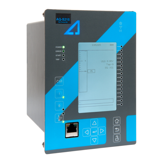
A A Q Q -S215 -S215 3 Device user interface Instruction manual Version: 2.11 When the unit is powered on, the green "Power" LED is lit. When the red "Error" LED is lit, the device has an internal (hardware or software) error that affects the operation of the unit. The activation of the yellow "Start"... -
Page 15: Navigation In The Main Configuration Menus
A A Q Q -S215 -S215 3 Device user interface Instruction manual Version: 2.11 3.2.2 Navigation in the main configuration menus All the settings in this device have been divided into the following six (6) main configuration menus: • General •... - Page 16 A A Q Q -S215 -S215 3 Device user interface Instruction manual Version: 2.11 Figure. 3.3 - 4. General menu structure. Device info Figure. 3.3 - 5. Device info. © Arcteq Relays Ltd IM00023...
- Page 17 A A Q Q -S215 -S215 3 Device user interface Instruction manual Version: 2.11 Table. 3.3 - 3. Parameters and indications in the General menu. Name Range Step Default Description Device name Unitname The file name uses these fields when loading the .aqs configuration file from the AQ-200 Device location Unitlocation...
- Page 18 A A Q Q -S215 -S215 3 Device user interface Instruction manual Version: 2.11 Name Range Step Default Description If the user navigates to a menu and gives no input after a period of time defined with this Return to default view 0…3600 s 10 s parameter, the unit automatically returns to...
-
Page 19: Control Menu
A A Q Q -S215 -S215 3 Device user interface Instruction manual Version: 2.11 3.4 Control menu Main menu Figure. 3.4 - 7. Main menu structure. The Control main menu includes submenus (see the image above) for enabling the various control functions and objects ( Controls enabled ), for enabling and controlling the setting groups ( Setting groups) , for configuring the objects ( Objects) , for setting the various control functions ( Control functions) , and for configuring the inputs and outputs ( Device I/O) . - Page 20 A A Q Q -S215 -S215 3 Device user interface Instruction manual Version: 2.11 Setting groups Figure. 3.4 - 9. Setting groups submenu. The Setting groups submenu displays all the information related to setting group changing, such as the following: •...
- Page 21 A A Q Q -S215 -S215 3 Device user interface Instruction manual Version: 2.11 Objects Figure. 3.4 - 11. Objects submenu. Each activated object is visible in the Objects submenu. By default all objects are disabled unless specifically activated in the Controls → Controls enabled submenu. Each active object has four sections in their submenus: "Settings", "Application control"...
- Page 22 A A Q Q -S215 -S215 3 Device user interface Instruction manual Version: 2.11 OBJECT SET AND STATUS • L L oc ocal/R al/Remo emot t e sta e stat t us us: control access may be set to Local or Remote (Local by default; please note that when local control is enabled, the object cannot be controlled through the bus and vice versa).
- Page 23 A A Q Q -S215 -S215 3 Device user interface Instruction manual Version: 2.11 Figure. 3.4 - 13. Application control section. You can connect object statuses directly to specific physical outputs in the "Signal connections" subsection ( Control → Application control ). A status can be connected to output relays, as well as to user-configurable LEDs.
- Page 24 A A Q Q -S215 -S215 3 Device user interface Instruction manual Version: 2.11 The "Registers"section stores the function's specific fault data. There are twelve (12) registers, and each of them includes data such as opening and closing times, command types and request failures. The data included in the register depend on the protection function.
- Page 25 A A Q Q -S215 -S215 3 Device user interface Instruction manual Version: 2.11 Each control function that has been activated is listed in the Control functions submenu (see the middle image above). This submenu includes the following sections: "Info", "Settings", "Registers", "I/O" and "Events".
- Page 26 A A Q Q -S215 -S215 3 Device user interface Instruction manual Version: 2.11 The stage settings vary depending on which control function they are a part of. By default only one setting group of the eight available setting groups is activated. You can enable more groups in the Control →...
- Page 27 A A Q Q -S215 -S215 3 Device user interface Instruction manual Version: 2.11 Figure. 3.4 - 20. I/O section. The "I/O" section is divided into two subsections: "Direct output control" and "Blocking input control". In "Direct output control" you can connect the stage's signals to physical outputs, either to an output relay or an LED (START or TRIP LEDs or one of the 16 user configurable LEDs).
- Page 28 A A Q Q -S215 -S215 3 Device user interface Instruction manual Version: 2.11 Figure. 3.4 - 21. Events section. You can mask on and mask off events related to an object's stage in "Event mask". By default all events are masked off.
- Page 29 A A Q Q -S215 -S215 3 Device user interface Instruction manual Version: 2.11 Figure. 3.4 - 23. Digital input section. All settings related to digital inputs can be found in the "Digital inputs" section. The "Digital inputs settings" subsection includes various settings for the inputs: the polarity selection determines whether the input is Normal Open (NO) or Normal Closed (NC) as well as the activation threshold voltage (16…200 V AC/DC, step 0.1 V) and release threshold voltage (10…200 V AC/DC, step 0.1 V) for each available input.
- Page 30 A A Q Q -S215 -S215 3 Device user interface Instruction manual Version: 2.11 The "Digital outputs settings" subsection lets you select the polarity for each output; they can be either Normal Open (NO) or Normal Closed (NC). The default polarity is Normal Open. The operational delay of an output contact is approximately 5 ms.
- Page 31 A A Q Q -S215 -S215 3 Device user interface Instruction manual Version: 2.11 Figure. 3.4 - 26. Device I/O matrix section. Through the "Device I/O matrix" section you can connect digital inputs, logical outputs, protection stage status signals (START, TRIP, BLOCKED, etc.), object status signals and many other binary signals to output relays, or to LEDs configured by the used.
- Page 32 A A Q Q -S215 -S215 3 Device user interface Instruction manual Version: 2.11 Figure. 3.4 - 28. Programmable mimic indicators section. Programmable mimic indicators can be placed into the mimic to display a text based on the status of a given binary signal (digital input, logical signal, status of function start/tripped/blocked signals etc.).
-
Page 33: Communication Menu
A A Q Q -S215 -S215 3 Device user interface Instruction manual Version: 2.11 GOOSE inputs are mainly used for controlling purposes and in conjunction with the IEC 61850 communication protocol. There are 64 GOOSE inputs signal status bits, and their status can be either 0 or 1. - Page 34 A A Q Q -S215 -S215 3 Device user interface Instruction manual Version: 2.11 Connections Figure. 3.5 - 31. View of the Connections submenu. The Connections submenu offers the following bits of information and settings: ETHERNET ETHERNET This section defines the IP settings for the Ethernet port in the back panel of the unit. •...
- Page 35 A A Q Q -S215 -S215 3 Device user interface Instruction manual Version: 2.11 Protocols Figure. 3.5 - 32. View of the Protocols submenu. The Protocols submenu offers access to the various communication protocol configuration menus. Some of the communication protocols use serial communication and some use Ethernet communication.
-
Page 36: Measurement Menu
A A Q Q -S215 -S215 3 Device user interface Instruction manual Version: 2.11 3.6 Measurement menu Figure. 3.6 - 33. Measurement section. The Measurement menu includes the following submenus: Transformers , Frequency , Current measurement , Voltage measurement , Power and energy measurement , Impedance calculations , and Phasors . - Page 37 A A Q Q -S215 -S215 3 Device user interface Instruction manual Version: 2.11 CT module Figure. 3.6 - 35. CT module section. The three main sections ("Phase CT scaling", "Residual I01 CT scaling" and "Residual I02 CT scaling") determine the ratio of the used transformers. Additionally, the nominal values are also determined in the CT module submenu.
- Page 38 A A Q Q -S215 -S215 3 Device user interface Instruction manual Version: 2.11 VT primary and secondary voltages must match with the connected voltage transformer in addition to the voltage measurement mode. These settings are then used for scaling the voltage channel input voltages to primary and per unit values as well as power and energy measurement values if current measurements are also available.
- Page 39 A A Q Q -S215 -S215 3 Device user interface Instruction manual Version: 2.11 Current measurement Figure. 3.6 - 38. Current measurement submenu. Current measurement submenu includes various individual measurements for each phase or phase-to- phase measurement. The Current measurement submenu has been divided into four sections: "Phase currents", "Residual currents", "Sequence currents", and "Harmonics".
- Page 40 A A Q Q -S215 -S215 3 Device user interface Instruction manual Version: 2.11 Voltage measurement Figure. 3.6 - 39. Voltage measurement submenu and System Voltages menu. Voltage measurement submenu includes various individual measurements for each phase or phase-to- phase measurement. The Voltage measurement submenu has been also divided into four sections: "Voltage inputs", "Sequence voltages", "System voltages", and "Harmonics".
- Page 41 A A Q Q -S215 -S215 3 Device user interface Instruction manual Version: 2.11 Power and energy measurement Figure. 3.6 - 40. Power and Energy measurement submenu. The Power and energy measurement submenu includes three sections: "Power and energy measurement settings", "Power measurements" and "Energy measurements". As the name suggests, the first section determines the settings by which the power and energy calculations are made.
-
Page 42: Monitoring Menu
A A Q Q -S215 -S215 3 Device user interface Instruction manual Version: 2.11 The Impedance calculations submenu is divided into four sections: "Impedance calculation settings", "Phase-to-phase impedances", "Phase-to-earth impedances" and "Positive sequence impedance". You can activate impedance calculations in the first section. "Phase-to-phase impedances" display the resistances and reactances of the three phase-to-phase connections, both primary and secondary, as well as the primary and secondary impedances and impedance angles. - Page 43 A A Q Q -S215 -S215 3 Device user interface Instruction manual Version: 2.11 Monitors enabled Figure. 3.7 - 44. Monitors enabled submenu. You can activate the selected monitor functions in the Monitors enabled submenu. By default all the control functions are disabled. All activated functions can be viewed in the Monitor functions submenu (see the section "Monitor functions"...
- Page 44 A A Q Q -S215 -S215 3 Device user interface Instruction manual Version: 2.11 Disturbance recorder Figure. 3.7 - 46. Disturbance recorder settings. The Disturbance recorder submenu has the following settings: • "Recorder enabled" enables or disables the recorder. • "Recorder status" indicates the status of the recorder. •...
-
Page 45: Configuring User Levels And Their Passwords
A A Q Q -S215 -S215 3 Device user interface Instruction manual Version: 2.11 • Enabling "Auto. get recordings" allows the device to automatically upload recordings to the designated FTP folder (which, in turn, allows any FTP client to read the recordings from the device's memory). - Page 46 A A Q Q -S215 -S215 3 Device user interface Instruction manual Version: 2.11 A number of stars are displayed in the upper right corner of the HMI; these indicate the current user level. The different user levels and their star indicators are as follows (also, see the image below for the HMI view): •...
- Page 47 A A Q Q -S215 -S215 3 Device user interface Instruction manual Version: 2.11 • User: Can view any menus and settings but cannot change any settings, nor operate breakers or other equipment. • Operator: Can view any menus and settings but cannot change any settings BUT can operate breakers and other equipment.
-
Page 48: Functions Unctions
A A Q Q -S215 -S215 4 Functions Instruction manual Version: 2.11 4 Functions 4.1 Functions included in AQ-S215 The AQ-S215 bay control device includes the following functions as well as the number of stages in those functions. Table. 4.1 - 4. Protection functions of AQ-S215. Name (number ANSI Description... -
Page 49: Measurements
A A Q Q -S215 -S215 4 Functions Instruction manual Version: 2.11 4.2 Measurements 4.2.1 Current measurement and scaling The current measurement module (CT module, or CTM) is used for measuring the currents from current transformers. The current measurements are updated every 5 milliseconds. The measured values are processed into the measurement database and they are used by measurement and protection functions. - Page 50 A A Q Q -S215 -S215 4 Functions Instruction manual Version: 2.11 For the measurements to be correct the user needs to ensure that the measurement signals are connected to the correct inputs, that the current direction is connected to the correct polarity, and that the scaling is set according to the nominal values of the current transformer.
- Page 51 A A Q Q -S215 -S215 4 Functions Instruction manual Version: 2.11 Table. 4.2.1 - 7. Initial data. P P ha hase curr se current C ent CT T : : R R ing cor ing core C e CT in Input I02: T in Input I02: L L oad ( oad (nominal):...
- Page 52 A A Q Q -S215 -S215 4 Functions Instruction manual Version: 2.11 Figure. 4.2.1 - 51. Setting the phase current transformer scalings to the protected object's nominal current. Once the measurement scaling is tied to the protected object's nominal current, the user must set the appropriate input for the "Nominal current In"...
- Page 53 A A Q Q -S215 -S215 4 Functions Instruction manual Version: 2.11 Figure. 4.2.1 - 53. Residual I02 CT scaling (sensitive). Displaying the scaling Depending on whether the scaling was done based on the CT primary values or the protected object's nominal current, the measurements are displayed slightly differently.
- Page 54 A A Q Q -S215 -S215 4 Functions Instruction manual Version: 2.11 Example of zero sequence CT scaling Zero sequence CT scaling (ZCT scaling) is done when a zero sequence CT instead of a ring core CT is part of the measurement connection. In such a case the zero sequence CT should be connected to the I02 channel which has lower CT scaling ranges (see the image below).
- Page 55 A A Q Q -S215 -S215 4 Functions Instruction manual Version: 2.11 Problem Solution The phase currents are connected to the measurement module but the order or polarity of one or all phases is incorrect. In device settings, go to Measurement → Phasors and check the "Phase current vectors"...
- Page 56 A A Q Q -S215 -S215 4 Functions Instruction manual Version: 2.11 Figure. 4.2.1 - 57. Common phase polarity problems. The following image presents the most common problems with network rotation (mix phases). These problems can be difficult to find because the measurement result is always the same in the device. If two phases are mixed together, the network rotation always follows the pattern IL1-IL3-IL2 and the measured negative sequence current is therefore always 1.00 (in.
- Page 57 A A Q Q -S215 -S215 4 Functions Instruction manual Version: 2.11 Figure. 4.2.1 - 58. Common network rotation (mixed phases) problems. Settings Table. 4.2.1 - 8. Settings of the Phase CT scaling. Name Range Step Default Description Scale • CT nom p.u. •...
- Page 58 A A Q Q -S215 -S215 4 Functions Instruction manual Version: 2.11 Name Range Step Default Description A feedback value; the calculated scaling factor that is the ratio between the set primary current and the set CT scaling nominal current. This parameter is only visible if the factor NOM option "Object In p.u."...
- Page 59 A A Q Q -S215 -S215 4 Functions Instruction manual Version: 2.11 Table. 4.2.1 - 11. Per-unit phase current measurements. Name Unit Range Step Description Phase current 0.000…1 The current fundamental frequency component (in p.u.) × In 0.001 250.000 from each of the phase current channels. ("Pha.curr.ILx") Phase current ILx TRMS...
- Page 60 A A Q Q -S215 -S215 4 Functions Instruction manual Version: 2.11 Table. 4.2.1 - 15. Per-unit residual current measurements. Name Unit Range Step Description The current measurement fundamental frequency Residual current I0x 0.00…1 × In 0.01 component (in p.u.) from the residual current channel I01 ("Res.curr.I0x") 250.00 or I02.
- Page 61 A A Q Q -S215 -S215 4 Functions Instruction manual Version: 2.11 Table. 4.2.1 - 18. Residual phase angle measurements. Name Unit Range Step Description Residual current angle I0x The residual current angle measurement from the I01 or 0.00…360.00 0.01 ("Res.curr.angle I02 current input.
- Page 62 A A Q Q -S215 -S215 4 Functions Instruction manual Version: 2.11 Name Unit Range Step Description Secondary zero sequence current The secondary measurement from the calculated 0.00…300.00 0.01 ("Sec.Zero sequence zero sequence current. curr.") Table. 4.2.1 - 22. Sequence phase angle measurements. Name Unit Range...
-
Page 63: Voltage Measurement And Scaling
A A Q Q -S215 -S215 4 Functions Instruction manual Version: 2.11 4.2.2 Voltage measurement and scaling The voltage measurement module (VT module, or VTM) is used for measuring the voltages from voltage transformers. The voltage measurements are updated every 5 milliseconds. The measured values are processed into the measurement database and they are used by measurement and protection functions. - Page 64 A A Q Q -S215 -S215 4 Functions Instruction manual Version: 2.11 Figure. 4.2.2 - 60. Connections. The following table presents the initial data of the connection. Table. 4.2.2 - 24. Initial data. P P ha hase v se volta oltage V ge VT T Z Z er ero sequence v...
- Page 65 A A Q Q -S215 -S215 4 Functions Instruction manual Version: 2.11 Figure. 4.2.2 - 61. Example connections for voltage line-to-line measurement. If only two line-to-line voltages are measured, the third one (U ) is calculated based on the U vectors.
- Page 66 A A Q Q -S215 -S215 4 Functions Instruction manual Version: 2.11 The image collection below presents the device's behavior when nominal voltage is injected into the device via secondary test equipment. The measurement mode is 3LN+U4 which means that the device is measuring line-to-neutral voltages.
- Page 67 A A Q Q -S215 -S215 4 Functions Instruction manual Version: 2.11 Problem Check / Resolution The voltages are connected to the measurement module but the order or polarity of The measured one or all phases is incorrect. In device settings, go to Measurement → Phasors and voltage amplitudes are check the "System voltage vectors"...
- Page 68 A A Q Q -S215 -S215 4 Functions Instruction manual Version: 2.11 Name Range Step Default Description Defines how the secondary voltage is scaled to the primary. "Broken Delta" is the most common mode. Does not affect how protection operates, it only affects the displayed primary voltages.
- Page 69 A A Q Q -S215 -S215 4 Functions Instruction manual Version: 2.11 Name Range Step Default Description The selection of the fourth voltage measurement channel's (U4) polarity (direction). The default setting is for the U4 Polarity positive voltage to flow from connector 7 to connector 8, with the secondary voltage's starpoint pointing towards the line.
- Page 70 A A Q Q -S215 -S215 4 Functions Instruction manual Version: 2.11 Table. 4.2.2 - 28. Secondary voltage measurements. Name Range Step Description Secondary The secondary voltage measurement fundamental frequency voltage Ux 0.00…500.00V 0.01V component from each of the voltage channels. ("Ux Volt sec") Secondary voltage Ux...
- Page 71 A A Q Q -S215 -S215 4 Functions Instruction manual Version: 2.11 Table. 4.2.2 - 32. Secondary sequence voltage measurements. Name Range Step Description Secondary positive 0.00…4 The secondary measurement from the calculated positive sequence voltage 0.01V 800.00V sequence voltage. ("Pos.seq.Volt.sec") Secondary negative 0.00…4...
- Page 72 A A Q Q -S215 -S215 4 Functions Instruction manual Version: 2.11 Name Range Step Description System voltage magnitude 0.00…1 The primary line-to-neutral UL1 voltage fundamental frequency component 0.01V (measured or calculated). You can also select the row where the unit for this is ("System 000.00V volt UL1...
- Page 73 A A Q Q -S215 -S215 4 Functions Instruction manual Version: 2.11 Name Range Step Description System voltage angle UL23 0.00…360.00° 0.01° The primary line-to-line angle UL23 (measured or calculated). ("System volt UL23 ang") System voltage angle UL31 0.00…360.00° 0.01° The primary line-to-line angle UL23 (measured or calculated). ("System volt UL31 ang")
- Page 74 A A Q Q -S215 -S215 4 Functions Instruction manual Version: 2.11 Table. 4.2.2 - 36. Harmonic voltage measurements. Name Range Step Description Harmonics calculation values • Percent Defines whether the harmonics are calculated as percentages ("Harm Abs.or • Absolute or absolute values.
- Page 75 A A Q Q -S215 -S215 4 Functions Instruction manual Version: 2.11 Figure. 4.2.2 - 65. Distance protection characteristics and directional overcurrent. Voltage memory activates when the above-mentioned criteria are met. Voltage memory uses the "VMEM activation voltage" parameter as voltage amplitude even when the actual measured voltage has decreased below it or close to zero.
- Page 76 A A Q Q -S215 -S215 4 Functions Instruction manual Version: 2.11 VMEM activ VMEM activa a tion v tion volta oltage ge and Mea Measur sured curr ed current condition 3I> ent condition 3I> When the voltage memory function is enabled, it activates when all line voltages drop below the "VMEM activation voltage"...
-
Page 77: Power And Energy Calculation
A A Q Q -S215 -S215 4 Functions Instruction manual Version: 2.11 Event block name Event names M1VT1 Voltage memory blocked ON M1VT1 Voltage memory blocked OFF 4.2.3 Power and energy calculation Power is divided into three magnitudes: apparent power (S), active power (P) and reactive power (Q). Energy measurement calculates magnitudes for active and reactive energy. - Page 78 A A Q Q -S215 -S215 4 Functions Instruction manual Version: 2.11 Figure. 4.2.3 - 69. Three-phase reactive power (Q) calculation. Active power can be to the forward or the reverse direction. The direction of active power can be indicated with the power factor (Cos (φ), or Cosine phi), which is calculated according the following formula: The direction of reactive power is divided into four quadrants.
- Page 79 A A Q Q -S215 -S215 4 Functions Instruction manual Version: 2.11 If the line-to-line voltages are measured but the zero sequence voltage is not measured or is not otherwise known, the three-phase power calculation is based on Aron’s theorem: Both cos(φ) and tan(φ) are calculated in the same way as in the line-to-neutral mode.
- Page 80 A A Q Q -S215 -S215 4 Functions Instruction manual Version: 2.11 Name Range Step Default Description • Undefined • Q1 Fwd Cap AV Indicates what the power VA quadrant is at VA Quadrant • Q2 Rev Ind AV Undefined that moment.
- Page 81 A A Q Q -S215 -S215 4 Functions Instruction manual Version: 2.11 Name Range Step Default Description DC 1…4 The set pulse size. An energy pulse 0.005kW/ Pulse 0…1800kW/var 1kW/Var is given every time the set magnitude magnitude is exceeded. DC 1…4 Pulse 0…1800s...
- Page 82 A A Q Q -S215 -S215 4 Functions Instruction manual Version: 2.11 Name Unit Range Step Description Lx Active power (P) 0.01 The active power of Phase Lx in kilowatts -1x10 …1x10 Lx Reactive power (Q) kVar -1x10 0.01 The reactive power of Phase Lx kilovars …1x10 Lx Tan(phi) 0.01...
- Page 83 A A Q Q -S215 -S215 4 Functions Instruction manual Version: 2.11 Table. 4.2.3 - 44. Single-phase energy calculations (L1...L3). Name Range Step Description Export Active Energy Lx (kWh or 0.01 The exported active energy of the phase. -1x10 …1x10 MWh) Import Active Energy (kWh or 0.01 The imported active energy of the phase.
- Page 84 A A Q Q -S215 -S215 4 Functions Instruction manual Version: 2.11 Name Value Name Value Name Value Name Value L1 (S) L1 (S) 4.08 MVA L2 (S) L2 (S) 6.15 MVA L3 (S) L3 (S) 9.77 MVA 3PH (S) H (S) 20.00 MVA L1 (P)
-
Page 85: Frequency Tracking And Scaling
A A Q Q -S215 -S215 4 Functions Instruction manual Version: 2.11 Name Values 3PH (S) 20.00 MVA 3PH (P) 17.32 MW 3PH (Q) 0.00 Mvar 3PH Tan 0.00 3PH Cos 0.87 4.2.4 Frequency tracking and scaling Measurement sampling can be set to the frequency tracking mode or to the fixed user- defined frequency sampling mode. - Page 86 A A Q Q -S215 -S215 4 Functions Instruction manual Version: 2.11 The measurement error with a fixed 50 Hz sampling The measurement error with frequency tracking frequency when the frequency changes. The constant when the frequency changes. The constant current current is 5 A, the frequency sweep is from 6 Hz to 75 is 5 A, the frequency sweep is from 6 Hz to 75 Hz.
- Page 87 A A Q Q -S215 -S215 4 Functions Instruction manual Version: 2.11 Name Range Step Default Description Defines the lower limit for the deviation from the Min. tracking system nomnal frequency to be tracked. If the frequency 0.001…75.000 0.001 0.001 Hz frequency decreases more than allowed from the allowed nominal value, the tracking is discarded and the...
- Page 88 A A Q Q -S215 -S215 4 Functions Instruction manual Version: 2.11 Name Range Step Default Description • Use track Defines the start of the sampling. Sampling can Start sampling frequency Use track begin with a previously tracked frequency, or with with •...
-
Page 89: General Menu
A A Q Q -S215 -S215 4 Functions Instruction manual Version: 2.11 4.3 General menu The General menu consists of basic settings and indications of the device. Additionally, the all activated functions and their status are displayed in the Protection , Control and Monitor profiles. Table. - Page 90 A A Q Q -S215 -S215 4 Functions Instruction manual Version: 2.11 Name Range Default Description • All • COM A If the device has a double Ethernet option card it is AQtivate ethernet port • Double possible to choose which ports are available for Ethernet connecting with AQtivate software.
-
Page 91: Protection Functions
A A Q Q -S215 -S215 4 Functions Instruction manual Version: 2.11 4.4 Protection functions 4.4.1 Resistance temperature detectors (RTD) Resistance temperature detectors (or RTDs) can be used to measure both temperatures of motors/ generators and ambient temperatures. Typically an RTD is a thermocouple or of type PT100. Up to three (3) separate RTD modules based on an external Modbus are supported;... - Page 92 A A Q Q -S215 -S215 4 Functions Instruction manual Version: 2.11 Name Range Step Default Description • InternalRTD1 Selects the measurement module. • InternalRTD2 Internal RTD modules are option cards S1...S16 module • ExtModuleA InternalRTD1 installed to the device. External •...
-
Page 93: Programmable Stage (Pgx>/<; 99)
A A Q Q -S215 -S215 4 Functions Instruction manual Version: 2.11 Function can be set to monitor the measurement data from previously set RTD channels. A single channel can be set to have several alarms if the user sets the channel to multiple sensor inputs. In each sensor setting the user can select the monitored module and channel, as well as the monitoring and alarm setting units (°C or °F). - Page 94 A A Q Q -S215 -S215 4 Functions Instruction manual Version: 2.11 Please note that setting the number of available stages does not activate those stages, as they also need to be enabled individually with the PSx >/< Enabled parameter. When enabled an active stage shows its current state (condition), the expected operating time and the time remaining to trip under the activation parameters.
- Page 95 A A Q Q -S215 -S215 4 Functions Instruction manual Version: 2.11 Name Description I0CALC Ang Angle of calculated residual current (degrees) I1 Ang Angle of positive sequence current (degrees) I2 Ang Angle of negative sequence current (degrees) I01ResP I01 primary current of a current-resistive component I01CapP I01 primary current of a current-capacitive component I01ResS...
- Page 96 A A Q Q -S215 -S215 4 Functions Instruction manual Version: 2.11 Name Description U1 pos.seq.V Ang Positive sequence voltage angle (degrees) U2 neg.seq.V Ang Negative sequence voltage angle (degrees) Table. 4.4.2 - 55. Power measurements Name Description S3PH Three-phase apparent power S (kVA) P3PH Three-phase active power P (kW) Q3PH...
- Page 97 A A Q Q -S215 -S215 4 Functions Instruction manual Version: 2.11 Name Description XSeqSec Positive Reactance X secondary (Ω) ZSeqPri Positive Impedance Z primary (Ω) ZSeqSec Positive Impedance Z secondary (Ω) ZSeqAngle Positive Impedance Z angle Table. 4.4.2 - 58. Conductances, susceptances and admittances (L1, L2, L3) Name Description GLxPri...
- Page 98 A A Q Q -S215 -S215 4 Functions Instruction manual Version: 2.11 Name Description F Thermal T Feeder thermal temperature T Thermal T Transformer thermal temperature RTD meas 1…16 RTD measurement channels 1…16 Ext RTD meas 1…8 External RTD measurement channels 1…8 (ADAM) mA input 7,8,15,16 mA input channels 7, 8, 15, 16 ASC 1…4...
- Page 99 A A Q Q -S215 -S215 4 Functions Instruction manual Version: 2.11 Name Range Description PSx >/< MeasMag1/ -5 000 000...5 000 The ratio between measured magnitude and the pick-up MagSet1 at the setting. moment PSx >/< MeasMag2/ -5 000 000...5 000 The ratio between measured magnitude and the pick-up MagSet2 at the setting.
- Page 100 A A Q Q -S215 -S215 4 Functions Instruction manual Version: 2.11 Table. 4.4.2 - 63. Comparator modes Mode Description G G r r ea eat t er than er than. If the measured signal is greater than the set pick-up level, the Over >...
-
Page 101: Control Functions
A A Q Q -S215 -S215 4 Functions Instruction manual Version: 2.11 Events and registers The programmable stage function (abbreviated "PGS" in event block names) generates events and registers from the status changes in the events listed below. The user can select which event messages are stored in the main event buffer: ON, OFF, or both. - Page 102 A A Q Q -S215 -S215 4 Functions Instruction manual Version: 2.11 Figure. 4.5.1 - 71. Simplified function block diagram of the setting group selection function. Setting group selection can be applied to each of the setting groups individually by activating one of the various internal logic inputs and connected digital inputs.
- Page 103 A A Q Q -S215 -S215 4 Functions Instruction manual Version: 2.11 Settings and signals The settings of the setting group control function include the active setting group selection, the forced setting group selection, the enabling (or disabling) of the forced change, the selection of the number of active setting groups in the application, as well as the selection of the setting group changed remotely.
- Page 104 A A Q Q -S215 -S215 4 Functions Instruction manual Version: 2.11 Table. 4.5.1 - 67. Signals of the setting group selection function. Name Description Setting The selection of Setting group 1 ("SG1"). Has the highest priority input in setting group control. Can be group controlled with pulses or static signals.
- Page 105 A A Q Q -S215 -S215 4 Functions Instruction manual Version: 2.11 Figure. 4.5.1 - 73. Setting group control – one-wire connection from Petersen coil status. Depending on the application's requirements, the setting group control can be applied either with a one-wire connection or with a two-wire connection by monitoring the state of the Petersen coil connection.
- Page 106 A A Q Q -S215 -S215 4 Functions Instruction manual Version: 2.11 Figure. 4.5.1 - 74. Setting group control – two-wire connection from Petersen coil status. © Arcteq Relays Ltd IM00023...
- Page 107 A A Q Q -S215 -S215 4 Functions Instruction manual Version: 2.11 Figure. 4.5.1 - 75. Setting group control – two-wire connection from Petersen coil status with additional logic. The images above depict a two-wire connection from the Petersen coil: the two images at the top show a direct connection, while the two images on the bottom include additional logic.
- Page 108 A A Q Q -S215 -S215 4 Functions Instruction manual Version: 2.11 Figure. 4.5.1 - 76. Entirely application-controlled setting group change with the cold load pick-up function. In these examples the cold load pick-up function's output is used for the automatic setting group change.
-
Page 109: Object Control And Monitoring
A A Q Q -S215 -S215 4 Functions Instruction manual Version: 2.11 Event block name Event names Remote Change SG Request OFF Local Change SG Request ON Local Change SG Request OFF Force Change SG ON Force Change SG OFF SG Request Fail Not configured SG ON SG Request Fail Not configured SG OFF Force Request Fail Force ON... - Page 110 A A Q Q -S215 -S215 4 Functions Instruction manual Version: 2.11 Figure. 4.5.2 - 77. Simplified function block diagram of the object control and monitoring function. Settings The following parameters help the user to define the object. The operation of the function varies based on these settings and the selected object type.
- Page 111 A A Q Q -S215 -S215 4 Functions Instruction manual Version: 2.11 Name Range Default Description • Withdrawable The selection of the object type. This selection defines the circuit breaker number of required digital inputs for the monitored object. This •...
- Page 112 A A Q Q -S215 -S215 4 Functions Instruction manual Version: 2.11 Table. 4.5.2 - 70. Object types. Name Functionalities Description Breaker cart position Circuit breaker position Circuit breaker control Withdrawable circuit Object ready check before The monitor and control configuration of the breaker closing breaker withdrawable circuit breaker.
- Page 113 A A Q Q -S215 -S215 4 Functions Instruction manual Version: 2.11 Table. 4.5.2 - 72. Operation settings. Name Range Step Default Description Determines the maximum time between open and close statuses when the breaker switches. If this set time is exceeded and both Breaker 0.02…500.00 0.02...
- Page 114 A A Q Q -S215 -S215 4 Functions Instruction manual Version: 2.11 Blocking and interlocking The interlocking and blocking conditions can be set for each controllable object, with Open and Close set separately. Blocking and interlocking can be based on any of the following: other object statuses, a software function or a digital input.
- Page 115 A A Q Q -S215 -S215 4 Functions Instruction manual Version: 2.11 Events and registers The object control and monitoring function (abbreviated "OBJ" in event block names) generates events and registers from the status changes in the events listed below. The user can select which event messages are stored in the main event buffer: ON, OFF, or both.
- Page 116 A A Q Q -S215 -S215 4 Functions Instruction manual Version: 2.11 Event block name Description OBJ1...OBJ10 Open Command Fail OBJ1...OBJ10 Close Command Fail OBJ1...OBJ10 Final trip On OBJ1...OBJ10 Final trip Off OBJ1...OBJ10 Contact Abrasion Alarm On OBJ1...OBJ10 Contact Abrasion Alarm Off OBJ1...OBJ10 Switch Operating Time Exceeded On OBJ1...OBJ10...
-
Page 117: Indicator Object Monitoring
A A Q Q -S215 -S215 4 Functions Instruction manual Version: 2.11 4.5.3 Indicator object monitoring The indicator object monitoring function takes care of the status monitoring of disconnectors. The function's sole purpose is indication and does not therefore have any control functionality. To control circuit breakers and/or disconnectors, please use the Object control and monitoring function. -
Page 118: Auto-Recloser (79)
A A Q Q -S215 -S215 4 Functions Instruction manual Version: 2.11 Events The indicator object monitoring function (abbreviated "CIN" in event block names) generates events from the status changes in the events listed below. The user can select which event messages are stored in the main event buffer: ON, OFF, or both. - Page 119 A A Q Q -S215 -S215 4 Functions Instruction manual Version: 2.11 The user can select whether there is a set time delay (called 'arcing time') between shots to burn the fault-causing object from the line, or whether normal protection operating times are applied. When a fault is not present when the breaker is closed but reappears soons after (called 'discrimination time' and 'reclaim time'), the auto-recloser function can either arm another shot or give the final trip command and the feeder becomes locked.
- Page 120 A A Q Q -S215 -S215 4 Functions Instruction manual Version: 2.11 This type of application normally uses an auto-recloser with two shots (one high-speed and one delayed) which are triggered by earth fault protection or overcurrent protection. Short-circuit protection is used for interlocking the auto-recloser in case a clear short-circuit fault occurs in the line.
- Page 121 A A Q Q -S215 -S215 4 Functions Instruction manual Version: 2.11 • from Start with two shots (high-speed succeeds). The signal status graphs describe the statuses of available requests, the statuses of the auto- recloser's internal signals, the statuses of the timers, the breaker controls from the auto- recloser function as well as the breaker status signals.
- Page 122 A A Q Q -S215 -S215 4 Functions Instruction manual Version: 2.11 Figure. 4.5.4 - 83. Signal status graph of the permanent earth fault auto-recloser cycle. 1. An earth fault is found in the protected line causing the I0Dir> protection to start calculating the operating time for a trip.
- Page 123 A A Q Q -S215 -S215 4 Functions Instruction manual Version: 2.11 10. The I0Dir> stage trips a third time and gives the REQ2 request to the function. However, as the function is in the process of calculating the S S ho hot2 R t2 Reclaim T eclaim Time...
- Page 124 A A Q Q -S215 -S215 4 Functions Instruction manual Version: 2.11 Figure. 4.5.4 - 85. Signal status graph of the semi-permanent earth fault auto-recloser cycle. 1. An earth fault is found in the protected line causing the I0Dir> protection to start calculating the operating time for a trip.
- Page 125 A A Q Q -S215 -S215 4 Functions Instruction manual Version: 2.11 10. The S S ho hot2 R t2 Reclaim T eclaim Time ime (10 s) is exceeded, and so the AR Running AR Running, S S ho hot 2 Running t 2 Running and AR2 R R equest equested...
- Page 126 A A Q Q -S215 -S215 4 Functions Instruction manual Version: 2.11 1. An earth fault is found in the protected line causing the I0Dir> protection to start calculating the operating time for a trip. 2. The I0Dir> trips and gives the "Open" command to the breaker's open coil. The auto- recloser function is initiated and the AR Running AR Running, AR2 R AR2 Request...
- Page 127 A A Q Q -S215 -S215 4 Functions Instruction manual Version: 2.11 Figure. 4.5.4 - 89. Signal status graph of the permanent overcurrent auto-recloser cycle. 1. An overcurrent is found in the protected line causing the I> protection to pick up. This activates the AR1 R AR1 Request equested...
- Page 128 A A Q Q -S215 -S215 4 Functions Instruction manual Version: 2.11 11. The circuit breaker is opened and the I> function's START signal is released, and simultaneously the REQ1 trip signal for auto-reclosing is released. The function is now in a steady lock-out state and waits for the user to manually reset and re-initialize the function by closing the breaker.
- Page 129 A A Q Q -S215 -S215 4 Functions Instruction manual Version: 2.11 2. The S S ho hot1 Star t1 Start T t Time ime (500 ms) for has elapsed and the auto-recloser function starts running (AR Running Running). This sends an "Open" command to the breaker. 3.
- Page 130 A A Q Q -S215 -S215 4 Functions Instruction manual Version: 2.11 Figure. 4.5.4 - 93. Signal status graph of the transient overcurrent auto-recloser cycle. 1. An overcurrent is found in the protected line causing the I> protection to pick up. This activates the AR1 R AR1 Request equested...
- Page 131 A A Q Q -S215 -S215 4 Functions Instruction manual Version: 2.11 Auto-recloser in meshed or ring networks A typical auto-recloser scheme cannot be applied directly to an overhead line network that has a distributed generation (DG) component; this situation will become more common as renewable power sources become more widespread.
- Page 132 A A Q Q -S215 -S215 4 Functions Instruction manual Version: 2.11 The auto-recloser is sometimes used in time-coordinated, IDMT-protected networks that have old mechanical relays with current-dependent release times. In these cases the operation of the protection selectivity must be guaranteed by allowing all relay timing devices to completely reset during dead time to maintain the correct time discrimination after reclosing to the fault.
- Page 133 A A Q Q -S215 -S215 4 Functions Instruction manual Version: 2.11 Figure. 4.5.4 - 95. Simplified function block diagram of the auto-recloser function. As the diagram above shows, the auto-recloser function is tied to and dependent on the block status information and configuration of the object control and monitoring function.
- Page 134 A A Q Q -S215 -S215 4 Functions Instruction manual Version: 2.11 Signal Range Description Any binary Manual signal in the Allows for the manual resetting of the recloser if locked (e.g. due to Final Trip). reset device Any binary Locks the auto-recloser so that it requires a manual reset before its operation can be signal in the Locking...
- Page 135 A A Q Q -S215 -S215 4 Functions Instruction manual Version: 2.11 Signal Description The signal "AR1 Request ON" is activated and displayed when the function is executing a shot Request requested by REQ1. The signal "AR2 Request ON" is activated and displayed when the function is executing a shot Request requested by REQ2.
- Page 136 A A Q Q -S215 -S215 4 Functions Instruction manual Version: 2.11 Signal Description Operation The signal "AR Operation inhibit" is activated and displayed when the function is in Inhibit mode. inhibit AR Locked The signal "AR Locked" is activated and displayed when the function is in Locked mode. Setting parameters The auto-recloser function has settings that the user can freely configure.
- Page 137 A A Q Q -S215 -S215 4 Functions Instruction manual Version: 2.11 Setting Range Default Description • AR is inhibit • AR is ready • AR is locked • AR is running • AR is not running • Lock out delay is running •...
- Page 138 A A Q Q -S215 -S215 4 Functions Instruction manual Version: 2.11 Table. 4.5.4 - 83. AR General settings. Setting Range Step Default Description • Object 1 Defines the monitored and/or controlled object, and the • Object 2 Object for monitoring and/or controlling signals issued.
- Page 139 A A Q Q -S215 -S215 4 Functions Instruction manual Version: 2.11 Setting Range Step Default Description Defines the starting delay of the shot, i.e. the minimum time an ARx request has to be active before openign the breaker and entering the dead time delay counting.
- Page 140 A A Q Q -S215 -S215 4 Functions Instruction manual Version: 2.11 Figure. 4.5.4 - 96. Auto-recloser shot setting parameters. The auto-recloser function's shot settings are grouped into corresponding rows to make the setting of each shot straightforward. From the settings the user can see how the reclosing cycle is executed by each request, which functions initiate requests, and which shots and requests are in use.
- Page 141 A A Q Q -S215 -S215 4 Functions Instruction manual Version: 2.11 The setting example in the image above presents a two-shot auto-recloser. One can see that the REQ1 is started by I> START signal. The starting delay is 500 ms, followed by a 200 ms dead time; after a 200 ms "Arcing"...
- Page 142 A A Q Q -S215 -S215 4 Functions Instruction manual Version: 2.11 Events and registers The auto-recloser function (abbreviated "AR" in event block names) generates events and registers from the status changes in the events listed below. The user can select which event messages are stored in the main event buffer: ON, OFF, or both.
- Page 143 A A Q Q -S215 -S215 4 Functions Instruction manual Version: 2.11 Event block name Event names AR1 Request OFF AR2 Request ON AR2 Request OFF AR3 Request ON AR3 Request OFF AR4 Request ON AR4 Request OFF AR5 Request ON AR5 Request OFF Critical request ON Critical request OFF...
- Page 144 A A Q Q -S215 -S215 4 Functions Instruction manual Version: 2.11 Event block name Event names Dead time ON Dead time OFF Arc Discr time ON Arc Discr time OFF Shot reclaim time ON Shot reclaim time OFF Sequence finished OFF Final trip executed OFF Object "Close"...
- Page 145 A A Q Q -S215 -S215 4 Functions Instruction manual Version: 2.11 Date and time Registers dd.mm.yyyy AR Status: AR is ready, AR is not running, AR2 Requested, Executing Shot 1 hh:mm:ss.mss AR Timers: No timers running 0.000 s AR Status: AR is ready, AR is not running, Start time counting, AR2 Requested, Executing dd.mm.yyyy Shot 1 hh:mm:ss.mss...
- Page 146 A A Q Q -S215 -S215 4 Functions Instruction manual Version: 2.11 dd.mm.yyyy hh:mm:ss.mss 4044 AR1 Object "Close" request dd.mm.yyyy hh:mm:ss.mss 2957 OBJ1 Close request ON dd.mm.yyyy hh:mm:ss.mss 2958 OBJ1 Close Fail dd.mm.yyyy hh:mm:ss.mss 2959 OBJ1 Close request OFF dd.mm.yyyy hh:mm:ss.mss 2960 OBJ1 Close command ON dd.mm.yyyy hh:mm:ss.mss...
-
Page 147: Synchrocheck (Δv/Δa/Δf; 25)
A A Q Q -S215 -S215 4 Functions Instruction manual Version: 2.11 4.5.5 Synchrocheck (ΔV/Δa/Δf; 25) Checking the synchronization is important to ensure the safe closing of the circuit breaker between two systems. Closing the circuit breaker when the systems are not synchronized can cause several problems such as current surges which damage the interconnecting elements. - Page 148 A A Q Q -S215 -S215 4 Functions Instruction manual Version: 2.11 Figure. 4.5.5 - 98. Example connection of the synchrocheck function (2LL+U0+U4 mode, SYN1 in use, UL12 as reference voltage). Figure. 4.5.5 - 99. Example connection of the synchrocheck function (2LL+U3+U4 mode, SYN3 in use, UL12 as reference voltage).
- Page 149 A A Q Q -S215 -S215 4 Functions Instruction manual Version: 2.11 Figure. 4.5.5 - 100. Example application (synchrocheck over one breaker, with 3LL and 3LN VT connections). Figure. 4.5.5 - 101. Example application (synchrocheck over one breaker, with 2LL VT connection). ©...
- Page 150 A A Q Q -S215 -S215 4 Functions Instruction manual Version: 2.11 Figure. 4.5.5 - 102. Example application (synchrocheck over two breakers, with 2LL VT connection). © Arcteq Relays Ltd IM00023...
- Page 151 A A Q Q -S215 -S215 4 Functions Instruction manual Version: 2.11 Figure. 4.5.5 - 103. Example application (synchrocheck over three breakers, with 2LL+U3+U4 connection). NOTICE! TICE! When synchrocheck is used over three breakers, SYN1 and SYN2 must have the same reference voltage.
- Page 152 A A Q Q -S215 -S215 4 Functions Instruction manual Version: 2.11 Figure. 4.5.5 - 104. System states. Figure. 4.5.5 - 105. Simplified function block diagram of the SYN1 and SYN2 function. © Arcteq Relays Ltd IM00023...
- Page 153 A A Q Q -S215 -S215 4 Functions Instruction manual Version: 2.11 Figure. 4.5.5 - 106. Simplified function block diagram of the SYN3 function. Measured input The function block uses user selected voltage channels. The function monitors frequency, angle and fundamental frequency component value of the selected channels.
- Page 154 A A Q Q -S215 -S215 4 Functions Instruction manual Version: 2.11 Table. 4.5.5 - 88. Information displayed by the function. Name Range Step Description • SYN1 Blocked • SYN1 Ok • SYN1 Bypass • SYN1 SYN condition Vcond Ok Displays status of the control function.
- Page 155 A A Q Q -S215 -S215 4 Functions Instruction manual Version: 2.11 Setting parameters NOTE! TE! Before these settings can be accessed, a voltage channel (U3 or U4) must be set into the synchrocheck mode ("SS") in the voltage transformer settings ( Measurements → VT Module ). The general settings can be found at the synchrocheck function's INFO tab, while the synchrocheck stage settings can be found in the Settings tab ( Control →...
- Page 156 A A Q Q -S215 -S215 4 Functions Instruction manual Version: 2.11 Name Range Step Default Description Estimated Displays the estimated time until networks are 0.000…360.000s 0.005s closing synchronized. time Networks Displays the time it takes for both sides of the rotating 0.000…360.000s 0.005s...
- Page 157 A A Q Q -S215 -S215 4 Functions Instruction manual Version: 2.11 Events and registers The synchrocheck function (abbreviated "SYN" in event block names) generates events and registers from the status changes in the events listed below. The user can select which event messages are stored in the main event buffer: ON, OFF, or both.
-
Page 158: Milliampere Output Control
A A Q Q -S215 -S215 4 Functions Instruction manual Version: 2.11 Name Range SYNx Ref2 voltage The reference voltage of the selected stage. SYNx Volt Cond The voltage condition of the selected stage. SYNx Volt status The voltage status of the selected stage. SYNx Vdiff The voltage difference of the selected stage. - Page 159 A A Q Q -S215 -S215 4 Functions Instruction manual Version: 2.11 Name Range Default Description Enable mA output channels 7 and 8 Table. 4.5.6 - 94. Settings for mA output channels. Name Range Step Default Description Enable Enables and disables the selected mA output •...
-
Page 160: Programmable Control Switch
A A Q Q -S215 -S215 4 Functions Instruction manual Version: 2.11 Table. 4.5.6 - 95. Hardware indications. Name Range Description Hardware in mA output channels • None 1...4 • Slot • Slot • Slot Indicates the option card slot where the mA output card is located. -
Page 161: Analog Input Scaling Curves
A A Q Q -S215 -S215 4 Functions Instruction manual Version: 2.11 Table. 4.5.7 - 97. Settings. Name Range Default Description The user-settable name of the selected switch. The name Switch name Switchx can be up to 32 characters long. •... - Page 162 A A Q Q -S215 -S215 4 Functions Instruction manual Version: 2.11 • mA input in "4x mA input & 1x mA output" option cards • Digital input voltages Table. 4.5.8 - 99. Main settings (input channel). Name Range Step Default Description Analog input...
- Page 163 A A Q Q -S215 -S215 4 Functions Instruction manual Version: 2.11 Name Range Step Default Description -1 000 Displays the input measurement received by the Curve 1...10 input 000.00...1 000 0.00001 - curve. 000.00 -1 000 Defines the maximum input of the curve. If input Curve1...10 input 000.00...1 000 0.00001 0...
-
Page 164: Logical Outputs
A A Q Q -S215 -S215 4 Functions Instruction manual Version: 2.11 Name Range Step Default Description Scaled 0.000 output value Scales the measured milliampere signal at Point 2..10 Allows the user to create their own curve with up to twenty •... -
Page 165: Logical Inputs
A A Q Q -S215 -S215 4 Functions Instruction manual Version: 2.11 Table. 4.5.9 - 101. Logical output user description. Name Range Default Description User editable Logical 1...31 Description of the logical output. This description is used in description output characters several menu types for easier identification. - Page 166 A A Q Q -S215 -S215 4 Functions Instruction manual Version: 2.11 Figure. 4.5.10 - 110. Extending a logical input pulse. Logical input descriptions Logical inputs can be given a description. The user defined description are displayed in most of the menus: •...
-
Page 167: Monitoring Functions
A A Q Q -S215 -S215 4 Functions Instruction manual Version: 2.11 Table. 4.5.10 - 104. Event messages. Event block name Event names LOGIC2 Logical in 1...32 ON LOGIC2 Logical in 1...32 OFF 4.6 Monitoring functions 4.6.1 Current transformer supervision The current transformer supervision function (abbreviated CTS in this document) is used for monitoring the CTs as well as the wirings between the device and the CT inputs for malfunctions and wire breaks. - Page 168 A A Q Q -S215 -S215 4 Functions Instruction manual Version: 2.11 Figure. 4.6.1 - 112. Simplified function block diagram of the CTS function. Measured input The function block uses fundamental frequency component of phase current measurement values and residual current measurement values. The function supervises the angle of each current measurement channel.
- Page 169 A A Q Q -S215 -S215 4 Functions Instruction manual Version: 2.11 Signal Description Time base Fundamental frequency component of phase L3 (C) current Fundamental frequency component of residual input I01 Fundamental frequency component of residual input I02 General settings The following general settings define the general behavior of the function.
- Page 170 A A Q Q -S215 -S215 4 Functions Instruction manual Version: 2.11 Name Range Step Default Description Determines the pick-up threshold for phase current measurement. This setting limit defines the lower limit for 0.01…40.00×I 0.01×I 0.10×I the phase current's pick-up element. limit This condition has to be met for the function to activate.
- Page 171 A A Q Q -S215 -S215 4 Functions Instruction manual Version: 2.11 If the blocking signal is active when the pick-up element activates, a BLOCKED signal is generated and the function does not process the situation further. If the START function has been activated before the blocking signal, it resets and the release time characteristics are processed similarly to when the pick- up signal is reset.
- Page 172 A A Q Q -S215 -S215 4 Functions Instruction manual Version: 2.11 Figure. 4.6.1 - 114. Secondary circuit fault in phase L1 wiring. When a fault is detected and all conditions are met, the CTS timer starts counting. If the situation continues until the set time has passed, the function issues an alarm.
- Page 173 A A Q Q -S215 -S215 4 Functions Instruction manual Version: 2.11 Figure. 4.6.1 - 116. No wiring fault but heavy unbalance. If any of the phases exceed the I high limit setting, the operation of the function is not activated. This behavior is applied to short-circuits and earth faults even when the fault current exceeds the I high limit setting.
- Page 174 A A Q Q -S215 -S215 4 Functions Instruction manual Version: 2.11 If the I high limit and I low limit setting parameters are adjusted according to the application's normal behavior, the operation of the function can be set to be very sensitive for broken circuit and conductor faults.
- Page 175 A A Q Q -S215 -S215 4 Functions Instruction manual Version: 2.11 When phase current wire is broken all of the conditions are met in the CTS and alarm shall be issued in case if the situation continues until the set alarming time is met. Figure.
-
Page 176: Voltage Transformer Supervision (60)
A A Q Q -S215 -S215 4 Functions Instruction manual Version: 2.11 In this example there is a high-impedance earth fault. It does not activate the function, if the measurement conditions are met, while the calculated and measured residual current difference does not reach the limit. - Page 177 A A Q Q -S215 -S215 4 Functions Instruction manual Version: 2.11 Figure. 4.6.2 - 122. Secondary circuit fault in phase L1 wiring. Figure. 4.6.2 - 123. Simplified function block diagram of the VTS function. Measured input The function block uses fundamental frequency component of voltage measurement channels. The function uses calculated positive, negative and zero sequence voltages.
- Page 178 A A Q Q -S215 -S215 4 Functions Instruction manual Version: 2.11 Signal Description Time base Fundamental frequency component of U /V voltage measurement Fundamental frequency component of U /V voltage measurement Fundamental frequency component of U /V voltage measurement Pick-up settings The Voltage low pick-up and Voltage high detect setting parameters control the voltage-dependent pick-up and activation of the voltage transformer supervision function.
- Page 179 A A Q Q -S215 -S215 4 Functions Instruction manual Version: 2.11 Name Description Bus Live VTS problem Any of the VTS pick-up conditions are met. Read-only parameters The function's Info page displays useful, real-time information on the state of the protection function. It is accessed either through the device's HMI display, or through the setting tool software when it is connected to the device and its Live Edit mode is active.
- Page 180 A A Q Q -S215 -S215 4 Functions Instruction manual Version: 2.11 Operating time characteristics for activation This function supports definite time delay (DT). For detailed information on these delay types please refer to the chapter "General properties of a protection function" and its section "Operating time characteristics for trip and reset".
-
Page 181: Current Total Harmonic Distortion (Thd)
A A Q Q -S215 -S215 4 Functions Instruction manual Version: 2.11 Register Description • No voltage Volt 1, 2, 3, 4 status • Voltage OK • Low voltage • Bus dead • Bus live, VTS OK, Seq. OK System status •... - Page 182 A A Q Q -S215 -S215 4 Functions Instruction manual Version: 2.11 Figure. 4.6.3 - 125. Simplified function block diagram of the total harmonic distortion monitor function. Measured input The function block uses phase and residual current measurement channels. The function always uses FFT measurement of the whole harmonic specter of 32 components from each measured current channel.
- Page 183 A A Q Q -S215 -S215 4 Functions Instruction manual Version: 2.11 Pick-up settings The Phase , I01 and I02 s etting parameters control the the pick-up and activation of the function. They define the maximum allowed measured current THD before action from the function. Before the function activates alarm signals, their corresponding pick-up elements need to be activated with the setting parameters Enable phase THD alarm , Enable I01 THD alarm and Enable I02 THD alarm .
- Page 184 A A Q Q -S215 -S215 4 Functions Instruction manual Version: 2.11 Table. 4.6.3 - 119. Information displayed by the function. Name Range Description • Normal • Start THD condition Displays status of the monitoring function. • Alarm • Blocked Function blocking The block signal is checked in the beginning of each program cycle.
-
Page 185: Fault Locator (21Fl)
A A Q Q -S215 -S215 4 Functions Instruction manual Version: 2.11 Table. 4.6.3 - 121. Event messages. Event block name Event names THD1 THD Start Phase ON THD1 THD Start Phase OFF THD1 THD Start I01 ON THD1 THD Start I01 OFF THD1 THD Start I02 ON THD1... - Page 186 A A Q Q -S215 -S215 4 Functions Instruction manual Version: 2.11 Measured input Function block uses fundamental frequency component of current and voltage measurements to calculate phase-to-phase or phase-to-ground loop impedances. Table. 4.6.4 - 123. Measurement inputs of the 21FL function. Signal Description Time base...
- Page 187 A A Q Q -S215 -S215 4 Functions Instruction manual Version: 2.11 Table. 4.6.4 - 125. Required current conditions. Currents over limit P-E voltages available P-E voltages not available Recorded impedance No trigger No trigger No trigger If no current measurement requirements are fulfilled when the function receives a triggering signal, the function will not record impedance at all.
-
Page 188: Disturbance Recorder (Dr)
A A Q Q -S215 -S215 4 Functions Instruction manual Version: 2.11 Table. 4.6.4 - 127. Register content. Register Description Date and time dd.mm.yyyy hh:mm:ss.mss Event Event name • L1-L2 • L2-L3 • L3-L1 Fault type • L1-N • L2-N •... - Page 189 A A Q Q -S215 -S215 4 Functions Instruction manual Version: 2.11 Signal Description Residual current I coarse* I01c Residual current I fine* I01f I02c Residual current I coarse* Residual current I fine* I02f IL1” Phase current I (CT card 2) Phase current I (CT card 2) IL2”...
- Page 190 A A Q Q -S215 -S215 4 Functions Instruction manual Version: 2.11 Signal Description Line-to-neutral U or line-to-line voltage U (VT card 2) UL2(3)VT2 Line-to-neutral U or line-to-line voltage U (VT card 2) UL3(1)VT2 U0(SS)VT2 Zero sequence voltage U or synchrocheck voltage U (VT card 2) USup_2 Voltage measurement module voltage supply supervision (VT card 2)
- Page 191 A A Q Q -S215 -S215 4 Functions Instruction manual Version: 2.11 Signal Description Signal Description Secondary calculated Sec.calc.I0 Pha.Lx pow. THD Phase Lx power THD (L1, L2, L3) Residual I0x amplitude THD (I01, calc.I0 Calculated I0 Res.I0x ampl. THD I02) Calculated I0 phase calc.I0 Pha.angle...
- Page 192 A A Q Q -S215 -S215 4 Functions Instruction manual Version: 2.11 Signal Description Signal Description ILx resistive current in ILx Resistive Pos.seq. Resistive Current Primary positive sequence resistive per-unit values (IL1, Current p.u. Pri. current IL2, IL3) ILx reactive current in ILx Reactive Pos.seq.
- Page 193 A A Q Q -S215 -S215 4 Functions Instruction manual Version: 2.11 Signal Description Signal Description POW1 3PH Three-phase cosine Frequency based When true ("1"), all frequency- Cos(phi) protections blocked based protections are blocked. f atm. Protections (when not Frequency at the moment. If the Three-phase power 3PH PF measurable returns to...
- Page 194 A A Q Q -S215 -S215 4 Functions Instruction manual Version: 2.11 Signal Description Signal Description MBIO ModA Channel 1...8 of MBIO Mod A Logical Output x Logical output 1...64 Ch x Invalid is invalid MBIO ModB Channel 1...8 of MBIO Mod If NTP time synchronization is lost, NTP sync alarm Ch x Invalid...
- Page 195 A A Q Q -S215 -S215 4 Functions Instruction manual Version: 2.11 Name Range Description Clear oldest • - Clears the oldest stored disturbance recording. record • Clear Max. Displays the maximum number of recordings that can be stored in the number of 0…100 device's memory with settings currently in use.
- Page 196 A A Q Q -S215 -S215 4 Functions Instruction manual Version: 2.11 Name Range Default Description Enables and disables the automatic transfer of recordings. The recordings are taken from the device's protection CPU and transferred to the device's FTP directory in the communication CPU;...
- Page 197 A A Q Q -S215 -S215 4 Functions Instruction manual Version: 2.11 Application example This chapter presents an application example of how to set the disturbance recorder and analyze its output. The recorder is configured by using the setting tool software or device HMI, and the results are analyzed with the AQviewer software (is automatically downloaded and installed with AQtivate).
- Page 198 A A Q Q -S215 -S215 4 Functions Instruction manual Version: 2.11 Figure. 4.6.5 - 127. Effects of recording length and pre-triggering time signals. This example is based on the settings shown above. When there is at least one recording in the device's memory, that recording can be analyzed by using the AQviewer software (see the image below).
-
Page 199: Event Logger
A A Q Q -S215 -S215 4 Functions Instruction manual Version: 2.11 4.6.6 Event logger Event logger records status changes of protection functions, digital inputs, logical signals etc. Events are recorded with a timestamp. The time stamp resolution is 1 ms. Up to 15 000 events can be stored at once. - Page 200 A A Q Q -S215 -S215 4 Functions Instruction manual Version: 2.11 If the recording is done in the device, only the recording interval needs to be set before recording can be started. The setting tool estimates the maximum recording time, which depends on the recording interval.
- Page 201 A A Q Q -S215 -S215 4 Functions Instruction manual Version: 2.11 Res.Curr.I02 TRMS Pri U2Volt Pri L2 Exp/Imp React.Cap.E.bal.Mvarh Sec.Pha.Curr.IL1 U3Volt Pri L2 Exp/Imp React.Cap.E.bal.kvarh Sec.Pha.Curr.IL2 U4Volt Pri L2 Exp.React.Ind.E.Mvarh Sec.Pha.Curr.IL3 U1Volt Pri TRMS L2 Exp.React.Ind.E.kvarh Sec.Res.Curr.I01 U2Volt Pri TRMS L2 Imp.React.Ind.E.Mvarh Sec.Res.Curr.I02 U3Volt Pri TRMS...
- Page 202 A A Q Q -S215 -S215 4 Functions Instruction manual Version: 2.11 Pha.L1 pow. THD U1Volt Angle Exp.React.Cap.E.Mvarh Pha.L2 pow. THD U2Volt Angle Exp.React.Cap.E.kvarh Pha.L3 pow. THD U3Volt Angle Imp.React.Cap.E.Mvarh Res.I01 ampl. THD U4Volt Angle Imp.React.Cap.E.kvarh Res.I01 pow. THD Pos.Seq.Volt. Angle Exp/Imp React.Cap.E.bal.Mvarh Res.I02 ampl.
- Page 203 A A Q Q -S215 -S215 4 Functions Instruction manual Version: 2.11 I” Pri.Zero.Seq.Curr. System Volt UL1 ang S4 Measurement Res.Curr.I”01 TRMS Pri System Volt UL2 ang S5 Measurement Res.Curr.I”02 TRMS Pri System Volt UL3 ang S6 Measurement Sec.Pha.Curr.I”L1 System Volt U0 ang S7 Measurement Sec.Pha.Curr.I”L2 System Volt U1 ang...
-
Page 204: Fault Register
A A Q Q -S215 -S215 4 Functions Instruction manual Version: 2.11 Pha.IL”2 ampl. THD L1 Imp.Active Energy MWh Curve1 Output Pha.IL”3 ampl. THD L1 Imp.Active Energy kWh Curve2 Input Pha.IL”1 pow. THD L1 Exp/Imp Act. E balance MWh Curve2 Output Pha.IL”2 pow. - Page 205 A A Q Q -S215 -S215 4 Functions Instruction manual Version: 2.11 Figure. 4.6.8 - 129. 12 latest recordings can be accessed from HMI if "Fault registers" view has been enabled in "Carousel designer" tool. Measured input The function block uses analog current and voltage measurement values. Based on these values, the device calculates the primary and secondary values of currents, voltages, powers, and impedances as well as other values.
- Page 206 A A Q Q -S215 -S215 4 Functions Instruction manual Version: 2.11 Currents Description IL1Ang, IL2Ang, IL3Ang, I01Ang, I02Ang, I0CalcAng, The angles of each measured current. I1Ang, I2Ang V V olta oltages Descrip Description tion UL1Mag, UL2Mag, UL3Mag, UL12Mag, UL23Mag, The magnitudes of phase voltages, of phase-to-phase voltages, and of UL31Mag residual voltages.
- Page 207 A A Q Q -S215 -S215 4 Functions Instruction manual Version: 2.11 Currents Description Ref f2 The reference frequency 2. M thermal T The motor thermal temperature. F thermal T The feeder thermal temperature. T thermal T The transformer thermal temperature. RTD meas 1…16 The RTD measurement channels 1…16.
- Page 208 A A Q Q -S215 -S215 4 Functions Instruction manual Version: 2.11 Table. 4.6.8 - 137. Reported values. Name Range Description • - • I> Trip • I>> Trip • I>>> Trip • I>>>> Trip • IDir> Trip • IDir>> Trip •...
- Page 209 A A Q Q -S215 -S215 4 Functions Instruction manual Version: 2.11 Name Range Description • A(AB) • B(BC) • A-B(AB-BC) • C(CA) • A-C(AB-CA) • B-C(BC-CA) • A-B-C • Overfrequency Voltage fault type The voltage fault type. • Underfrequency •...
-
Page 210: Communica A Tion
A A Q Q -S215 -S215 5 Communication Instruction manual Version: 2.11 5 Communication 5.1 Connections menu "Connections" menu is found under "Communication" menu. It contains all basic settings of ethernet port and RS-485 serial port included with every AQ-200 device as well as settings of communication option cards. - Page 211 A A Q Q -S215 -S215 5 Communication Instruction manual Version: 2.11 Table. 5.1 - 140. Virtual Ethernet settings. Name Description Enable virtual adapter (No / Yes) Enable virtual adapter. Off by default. IP address Set IP address of the virtual adapter. Netmask Set netmask of the virtual adapter.
-
Page 212: Time Synchronization
A A Q Q -S215 -S215 5 Communication Instruction manual Version: 2.11 Name Range Description • None • ModbutRTU • ModbusIO Protocol • IEC103 Communication protocol used by serial fiber channels. • SPA • DNP3 • IEC101 • Off Echo Enable or disable echo. -
Page 213: Internal
A A Q Q -S215 -S215 5 Communication Instruction manual Version: 2.11 5.2.1 Internal If no external time synchronization source is available the mode should be set to "internal". This means that the AQ-200 device clock runs completely on its own. Time can be set to the device with AQtivate setting tool with Commands →... -
Page 214: Communication Protocols
A A Q Q -S215 -S215 5 Communication Instruction manual Version: 2.11 Name Range Description NTP-processed 0...4294967295 Displays the number of messages processed by the NTP protocol. message count NOTICE! TICE! A unique IP address must be reserved for the NTP client. The device's IP address cannot be used. - Page 215 A A Q Q -S215 -S215 5 Communication Instruction manual Version: 2.11 Name Range Step Default Description The device can be set to allow object control via • Remote IEC 61850 only from clients that are of category Control Station level control. This would mean that other Remote Control Authority switch •...
-
Page 216: Goose
A A Q Q -S215 -S215 5 Communication Instruction manual Version: 2.11 Name Range Step Default Description • All • COM A Determines which ports can use GOOSE GOOSE Ethernet port • Double communication. Visible if double ethernet option ethernet card is found in the device. -
Page 217: Modbus/Tcp And Modbus/Rtu
A A Q Q -S215 -S215 5 Communication Instruction manual Version: 2.11 • logic editor • matrix • block settings • • • etc. These settings can be found from Control → Device IO → Logical Signals → GOOSE IN Description . Table. -
Page 218: Iec 103
A A Q Q -S215 -S215 5 Communication Instruction manual Version: 2.11 Once the configuration file has been loaded, the user can access the Modbus map of the device via the AQtivate software ( Tools → Communication → Modbus Map ). Please note that holding registers start from 1. -
Page 219: Iec 101/104
A A Q Q -S215 -S215 5 Communication Instruction manual Version: 2.11 Name Range Step Default Description Slave address 1…254 Defines the IEC 103 slave address for the unit. Measurement interval 0…60 000 ms 1 ms 2000 ms Defines the interval for the measurements update. 5.3.4 IEC 101/104 The standards IEC 60870-5-101 and IEC 60870-5-104 are closely related. - Page 220 A A Q Q -S215 -S215 5 Communication Instruction manual Version: 2.11 Name Range Step Default Description Common Defines the common address of the application service data unit address 0…65 534 (ASDU) for the IEC 104 communication protocol. of ASDU APDU The maximum amount of time the slave waits for a transmitted timeout...
-
Page 221: Spa
A A Q Q -S215 -S215 5 Communication Instruction manual Version: 2.11 Name Range Step Default Description Reactive 0.1…1000.0kVar 0.1kVar 2kVar energy deadband Active power deadband 0.1…1000.0kW 0.1kW Reactive 0.1…1000.0kVar 0.1kVar 2kVar power deadband Apparent 0.1…1000.0kVA 0.1kVA 2kVA power deadband Power factor deadband 0.01…0.99 0.01... -
Page 222: Dnp3
A A Q Q -S215 -S215 5 Communication Instruction manual Version: 2.11 NOTICE! TICE! To access SPA map and event list, an .aqs configuration file should be downloaded from the device. 5.3.6 DNP3 DNP3 is a protocol standard which is controlled by the DNP Users Group (www.dnp.org). The implementation of a DNP3 slave is compliant with the DNP3 subset (level) 2, but it also contains some functionalities of the higher levels. - Page 223 A A Q Q -S215 -S215 5 Communication Instruction manual Version: 2.11 Default variations Table. 5.3.6 - 160. Default variations. Name Range Default Description • Var 1 Group 1 variation (BI) Var 1 Selects the variation of the binary signal. •...
-
Page 224: Modbus I/O
A A Q Q -S215 -S215 5 Communication Instruction manual Version: 2.11 Name Range Step Default Description Reactive 0.1…1000.0kVar 0.1kVar 2kVar power deadband Apparent 0.1…1000.0kVA 0.1kVA 2kVA power deadband Power factor deadband 0.01…0.99 0.01 0.05 Frequency deadband 0.01…1.00Hz 0.01Hz 0.1Hz Current deadband 0.01…50.00A 0.01A... -
Page 225: Analog Fault Registers
A A Q Q -S215 -S215 5 Communication Instruction manual Version: 2.11 Table. 5.3.7 - 163. Channel settings. Name Range Step Default Description • +/- 20mA • 4…20mA Selects the thermocouple or the mA input connected to the • Type J I/O module. - Page 226 A A Q Q -S215 -S215 5 Communication Instruction manual Version: 2.11 Measurable values Function block uses analog current and voltage measurement values. The device uses these values as the basis when it calculates the primary and secondary values of currents, voltages, powers, impedances and other values.
- Page 227 A A Q Q -S215 -S215 5 Communication Instruction manual Version: 2.11 Signals Description cosfi3PH cosfiL1 Cos (φ) of three-phase powers and phase powers. cosfiL2 cosfiL3 Impedances and admittances RL12, RL23, RL31 XL12, XL23, XL31 RL1, RL2, RL3 Phase-to-phase and phase-to-neutral resistances, reactances and XL1, XL2, XL3 impedances.
- Page 228 A A Q Q -S215 -S215 5 Communication Instruction manual Version: 2.11 Name Range Step Default Description • Currents • Voltages Slot X magnitude • Powers Selects the measured magnitude catecory Currents selection • Impedance (ZRX) and of the chosen slot. admittance (YGB) •...
-
Page 229: Connections Of Aq-S215
A A Q Q -S215 -S215 6 Connections and application examples Instruction manual Version: 2.11 6 Connections and application examples 6.1 Connections of AQ-S215 Figure. 6.1 - 130. AQ-S215 variant without add-on modules. © Arcteq Relays Ltd IM00023... - Page 230 A A Q Q -S215 -S215 6 Connections and application examples Instruction manual Version: 2.11 Figure. 6.1 - 131. AQ-S215 variant with digital input and output modules. © Arcteq Relays Ltd IM00023...
-
Page 231: Application Example And Its Connections
A A Q Q -S215 -S215 6 Connections and application examples Instruction manual Version: 2.11 Figure. 6.1 - 132. AQ-S215 application example with function block diagram. AQ-S215 Device I/O Add-on 3 (IL) 4 voltage 1...3 3 slots 2 (I0) channels Monitoring functions 21FL Fault... -
Page 232: Two-Phase, Three-Wire Aron Input Connection
A A Q Q -S215 -S215 6 Connections and application examples Instruction manual Version: 2.11 Figure. 6.2 - 133. Application example and its connections. 6.3 Two-phase, three-wire ARON input connection This chapter presents the two-phase, three-wire ARON input connection for any AQ-200 series device with a current transformer. -
Page 233: Trip Circuit Supervision (95)
A A Q Q -S215 -S215 6 Connections and application examples Instruction manual Version: 2.11 Figure. 6.3 - 134. ARON connection. The ARON input connection can measure the load symmetrically despite the fact that one of the CTs is missing from the installation. Normally, Phase 2 does not have a current transformer installed as an external fault is much more likely to appear on Lines 1 or 3. - Page 234 A A Q Q -S215 -S215 6 Connections and application examples Instruction manual Version: 2.11 Figure. 6.4 - 135. Trip circuit supervision with one DI and one non-latched trip output. Note that the digital input that monitors the circuit is normally closed, and the same applies to the alarm relay if one is used.
- Page 235 A A Q Q -S215 -S215 6 Connections and application examples Instruction manual Version: 2.11 Figure. 6.4 - 137. Non-latched trip contact. When the auto-reclosing function is used in feeder applications, the trip output contacts must be non- latched. Trip circuit supervision is generally easier and more reliable to build with non-latched outputs. The open coil remains energized only as long as the circuit breaker is opened and the output releases.
- Page 236 A A Q Q -S215 -S215 6 Connections and application examples Instruction manual Version: 2.11 The trip circuit with a latched output contact can be monitored, but only when the circuit breaker's status is "Closed". Whenever the breaker is open, the supervision is blocked by an internal logic scheme.
-
Page 237: Construction And Installation Tion
A A Q Q -S215 -S215 7 Construction and installation Instruction manual Version: 2.11 7 Construction and installation 7.1 Construction AQ-X215 is a member of the modular and scalable AQ-200 series, and it includes three (3) configurable and modular add-on card slots. As a standard configuration the device includes the CPU module (which consists of the CPU, a number of inputs and outputs, and the power supply) as well as one separate voltage measurement module and one separate current measurement module. - Page 238 A A Q Q -S215 -S215 7 Construction and installation Instruction manual Version: 2.11 The figure below presents the start-up hardware scan order of the device as well as the I/O naming principles. Figure. 7.1 - 141. AQ-X215 hardware scanning and I/O naming principles. 1.
-
Page 239: Cpu Module
A A Q Q -S215 -S215 7 Construction and installation Instruction manual Version: 2.11 6. Scan Scans Slot E, and moves to the next slot if Slot E is empty. If the scan finds an 8DI module, it reserves the designations "DI4", "DI5", "DI6", "DI7", "DI8", "DI9", "DI10" and "DI11" to this slot. If Slot C also has an 8DI module (and therefore has already reserved these designations), the device reserves the designations "DI12", "DI13", "DI14", "DI15", "DI16", "DI17", "DI18"... - Page 240 A A Q Q -S215 -S215 7 Construction and installation Instruction manual Version: 2.11 Module connectors Table. 7.2 - 167. Module connector descriptions. Connector Description Communication port A, or the RJ-45 port. Used for the setting tool connection and for IEC 61850, COM A Modbus/TCP, IEC 104, DNP3 and station bus communications.
- Page 241 A A Q Q -S215 -S215 7 Construction and installation Instruction manual Version: 2.11 Digital input settings The settings described in the table below can be found at Control → Device I/O → Digital input settings in the device settings. Table.
-
Page 242: Current Measurement Module
A A Q Q -S215 -S215 7 Construction and installation Instruction manual Version: 2.11 Please note that the mechanical delay of the relay is no not t included in these approximations. 7.3 Current measurement module Figure. 7.3 - 143. Module connections with standard and ring lug terminals. Connector Description CTM 1-2... -
Page 243: Voltage Measurement Module
A A Q Q -S215 -S215 7 Construction and installation Instruction manual Version: 2.11 For further details please refer to the "Current measurement" chapter in the “Technical data” section of this document. 7.4 Voltage measurement module Figure. 7.4 - 144. Voltage measurement module. Connector Description VTM 1-2... -
Page 244: Option Cards
A A Q Q -S215 -S215 7 Construction and installation Instruction manual Version: 2.11 7.5 Option cards 7.5.1 Digital input module (optional) Figure. 7.5.1 - 145. Digital input module (DI8) with eight add-on digital inputs. Description (x = the number of digital inputs in other modules that preceed this one in the Connector configuration) DIx + 1... - Page 245 A A Q Q -S215 -S215 7 Construction and installation Instruction manual Version: 2.11 For the naming convention of the digital inputs provided by this module please refer to the chapter titled "Construction and installation". For technical details please refer to the chapter titled "Digital input module" in the "Technical data" section of this document.
- Page 246 A A Q Q -S215 -S215 7 Construction and installation Instruction manual Version: 2.11 Figure. 7.5.1 - 146. Digital input state when energizing and de-energizing the digital input channels. Digital input descriptions Option card inputs can be given a description. The user defined description are displayed in most of the menus: •...
-
Page 247: Digital Output Module (Optional)
A A Q Q -S215 -S215 7 Construction and installation Instruction manual Version: 2.11 7.5.2 Digital output module (optional) Figure. 7.5.2 - 147. Digital output module (DO5) with five add-on digital outputs. Connector Description X 1–2 OUTx + 1 (1 and 2 pole NO) X 3–4... -
Page 248: Rtd Input Module (Optional)
A A Q Q -S215 -S215 7 Construction and installation Instruction manual Version: 2.11 • block settings • • • etc. Table. 7.5.2 - 173. Digital output user description. Name Range Default Description User editable 1...31 Description of the digital output. This description is used in several OUTx description OUTx characters... -
Page 249: Serial Rs-232 Communication Module (Optional)
A A Q Q -S215 -S215 7 Construction and installation Instruction manual Version: 2.11 Figure. 7.5.3 - 149. RTD sensor connection types. 7.5.4 Serial RS-232 communication module (optional) Figure. 7.5.4 - 150. Serial RS-232 module connectors. Connector Name Description • Serial-based communications •... - Page 250 A A Q Q -S215 -S215 7 Construction and installation Instruction manual Version: 2.11 Connector Name Description COM F – +24 V input Optional external auxiliary voltage for serial fiber Pin 1 COM F – Optional external auxiliary voltage for serial fiber Pin 2 COM F –...
-
Page 251: Lc Or Rj45 100 Mbps Ethernet Communication Module (Optional)
A A Q Q -S215 -S215 7 Construction and installation Instruction manual Version: 2.11 7.5.5 LC or RJ45 100 Mbps Ethernet communication module (optional) Figure. 7.5.5 - 151. LC and RJ45 100 Mbps Ethernet module connectors. Connector Description (LC ports) Description (RJ45) •... -
Page 252: Double St 100 Mbps Ethernet Communication Module (Optional)
A A Q Q -S215 -S215 7 Construction and installation Instruction manual Version: 2.11 7.5.6 Double ST 100 Mbps Ethernet communication module (optional) Figure. 7.5.6 - 152. Double ST 100 Mbps Ethernet communication module connectors. Connector Description Two-pin connector • IRIG-B input •... - Page 253 A A Q Q -S215 -S215 7 Construction and installation Instruction manual Version: 2.11 Figure. 7.5.6 - 153. Example of a ring configuration. Figure. 7.5.6 - 154. Example of a multidrop configuration. © Arcteq Relays Ltd IM00023...
-
Page 254: Double Rj45 10/100 Mbps Ethernet Communication Module (Optional)
A A Q Q -S215 -S215 7 Construction and installation Instruction manual Version: 2.11 7.5.7 Double RJ45 10/100 Mbps Ethernet communication module (optional) Figure. 7.5.7 - 155. Double RJ-45 10/100 Mbps Ethernet communication module. Connector Description Two-pin connector • IRIG-B input •... -
Page 255: Milliampere Output (Ma) I/O Module (Optional)
A A Q Q -S215 -S215 7 Construction and installation Instruction manual Version: 2.11 Figure. 7.5.7 - 156. Example of a multidrop configuration. 7.5.8 Milliampere output (mA) I/O module (optional) Figure. 7.5.8 - 157. Milliampere output (mA) I/O module connections. Connector Description Pin 1... -
Page 256: Milliampere Input (Ma) I/O Module (Optional)
A A Q Q -S215 -S215 7 Construction and installation Instruction manual Version: 2.11 Connector Description Pin 5 mA OUT 3 + connector (0…24 mA) Pin 6 mA OUT 3 – connector (0…24 mA) Pin 7 mA OUT 4 + connector (0…24 mA) Pin 8 mA OUT 4 –... -
Page 257: Dimensions And Installation
A A Q Q -S215 -S215 7 Construction and installation Instruction manual Version: 2.11 Connector Description Pin 6 mA OUT 3 – connector (0…24 mA) Pin 7 mA OUT 4 + connector (0…24 mA) Pin 8 mA OUT 4 – connector (0…24 mA) Pin 9 mA IN 1 + connector (0…33 mA) Pin 10... - Page 258 A A Q Q -S215 -S215 7 Construction and installation Instruction manual Version: 2.11 Figure. 7.6 - 160. Device installation. © Arcteq Relays Ltd IM00023...
- Page 259 A A Q Q -S215 -S215 7 Construction and installation Instruction manual Version: 2.11 Figure. 7.6 - 161. Panel cutout dimensions and device spacing. © Arcteq Relays Ltd IM00023...
-
Page 260: Technic Echnical Da Al Data Ta
A A Q Q -S215 -S215 8 Technical data Instruction manual Version: 2.11 8 Technical data 8.1 Hardware 8.1.1 Measurements 8.1.1.1 Current measurement Table. 8.1.1.1 - 174. Technical data for the current measurement module. General information Spare part code #SP-2XX-CM Compatibility AQ-210 and AQ-250 series models Connections... - Page 261 A A Q Q -S215 -S215 8 Technical data Instruction manual Version: 2.11 25 A (continuous) 100 A (for 10 s) Thermal withstand 500 A (for 1 s) 1250 A (for 0.01 s) Frequency measurement From 6…75 Hz fundamental, up to the 31 harmonic current range Current measurement range...
-
Page 262: Voltage Measurement
A A Q Q -S215 -S215 8 Technical data Instruction manual Version: 2.11 8.1.1.2 Voltage measurement Table. 8.1.1.2 - 175. Technical data for the voltage measurement module. General information Spare part code #SP-2XX-VT Compatibility AQ 200 series and AQ 250 series models Connection Measurement channels/VT inputs 4 independent VT inputs (U1, U2, U3 and U4) -
Page 263: Power And Energy Measurement
A A Q Q -S215 -S215 8 Technical data Instruction manual Version: 2.11 Voltage inputs Phase current inputs: I (A), I (B), I Current inputs (back-up frequency) Pick-up 2.00…50.00 %U , setting step 0.01 x %U Pick-up voltage setting Pick-up current setting (optional) 0.01…50.00 ×... -
Page 264: Frequency Measurement
A A Q Q -S215 -S215 8 Technical data Instruction manual Version: 2.11 8.1.1.5 Frequency measurement Table. 8.1.1.5 - 178. Frequency measurement accuracy. Frequency measurement performance Frequency measuring range 6…75 Hz fundamental, up to the 31 harmonic current or voltage Inaccuracy <1 mHz 8.1.2 CPU &... -
Page 265: Cpu Communication Ports
A A Q Q -S215 -S215 8 Technical data Instruction manual Version: 2.11 Table. 8.1.2.1 - 181. Power supply model B Rated values Rated auxiliary voltage 18…72 VDC < 7 W (no option cards) Power consumption < 15 W (maximum number of option cards) Maximum permitted interrupt time <... -
Page 266: Cpu Digital Inputs
A A Q Q -S215 -S215 8 Technical data Instruction manual Version: 2.11 Table. 8.1.2.2 - 184. Rear panel system communication port B. Port Port media Copper RS-485 Number of ports Features Modbus/RTU IEC 103 Port protocols IEC 101 DNP3 Data transfer rate 65 580 kB/s System integration... -
Page 267: Option Cards
A A Q Q -S215 -S215 8 Technical data Instruction manual Version: 2.11 Breaking capacity, DC (L/R = 40 ms) at 48 VDC at 110 VDC 0.4 A at 220 VDC 0.2 A Control rate 5 ms Settings Polarity Software settable: Normally Open / Normally Closed Table. -
Page 268: Digital Output Module
A A Q Q -S215 -S215 8 Technical data Instruction manual Version: 2.11 Pick-up delay Software settable: 0…1800 s Drop-off delay Software settable: 0…1800 s Polarity Software settable: Normally On/Normally Off Terminal block connection Screw connection terminal block (standard) Phoenix Contact MSTB 2,5/10-ST-5,08 Spring cage terminals block (option) Phoenix Contact FKC 2,5/10-STF-5,08 Solid or stranded wire... -
Page 269: Milliampere Output Module (Ma Out & Ma In)
A A Q Q -S215 -S215 8 Technical data Instruction manual Version: 2.11 8.1.3.3 Milliampere output module (mA out & mA in) Table. 8.1.3.3 - 190. Technical data for the milliampere output module. General information Spare part code #SP-2XX-MA Compatibility AQ-200 series &... -
Page 270: Rtd Input Module
A A Q Q -S215 -S215 8 Technical data Instruction manual Version: 2.11 Input magnitudes 4 × mA input signal (DC) Output magnitudes 1 × mA output signal (DC) mA input Range (hardware) 0...33 mA Range (measurement) 0...24 mA Inaccuracy ±0.1 mA Update cycle 5...10 000 ms, setting step 5 ms... -
Page 271: Serial Fiber Communication Module
A A Q Q -S215 -S215 8 Technical data Instruction manual Version: 2.11 8.1.3.6 RS-232 & serial fiber communication module Table. 8.1.3.6 - 193. Technical data for the RS-232 & serial fiber communication module. General information PP Spare part code #SP-2XX-232PP PG Spare part code #SP-2XX-232PG... -
Page 272: Double St 100 Mbps Ethernet Communication Module
A A Q Q -S215 -S215 8 Technical data Instruction manual Version: 2.11 8.1.3.8 Double ST 100 Mbps Ethernet communication module Table. 8.1.3.8 - 195. Technical data for the double ST 100 Mbps Ethernet communication module. General information Spare part code #SP-2XX-2XST Compatibility AQ-200 series &... -
Page 273: Functions
A A Q Q -S215 -S215 8 Technical data Instruction manual Version: 2.11 8.2 Functions 8.2.1 Control functions 8.2.1.1 Setting group selection Table. 8.2.1.1 - 197. Technical data for the setting group selection function. Settings and control modes Setting groups 8 independent, control-prioritized setting groups Control scale Common for all installed functions which support setting groups... -
Page 274: Indicator Object Monitoring
A A Q Q -S215 -S215 8 Technical data Instruction manual Version: 2.11 External object control time <75 ms Object control during auto-reclosing See the technical sheet for the auto-reclosing function. 8.2.1.3 Indicator object monitoring Table. 8.2.1.3 - 199. Technical data for the indicator object monitoring function. General Number of objects Supported object types... -
Page 275: Synchrocheck (Δv/Δa/Δf; 25)
A A Q Q -S215 -S215 8 Technical data Instruction manual Version: 2.11 Instant starting time Instant operation time Protection activation delay + 15 ms (Protection + AR delay) 8.2.1.5 Synchrocheck (ΔV/Δa/Δf; 25) Table. 8.2.1.5 - 201. Technical data for the synchrocheck function. Input signals Voltage inputs U1, U2, U3 or U4 voltage channel... -
Page 276: Monitoring Functions
A A Q Q -S215 -S215 8 Technical data Instruction manual Version: 2.11 8.2.2 Monitoring functions 8.2.2.1 Current transformer supervision Table. 8.2.2.1 - 202. Technical data for the current transformer supervision function. Measurement inputs Phase current inputs: I (A), I (B), I Residual current channel I (Coarse) (optional) -
Page 277: Current Total Harmonic Distortion
A A Q Q -S215 -S215 8 Technical data Instruction manual Version: 2.11 Pick-up settings: 0.05…0.50 × U , setting step 0.01 × U - Voltage (low pick-up) - Voltage (high pick-up) 0.50…1.10 × U , setting step 0.01 × U - Angle shift limit 2.00…90.00 deg, setting step 0.10 deg Inaccuracy:... -
Page 278: Fault Locator (21Fl)
A A Q Q -S215 -S215 8 Technical data Instruction manual Version: 2.11 ±3 % of the set pick-up value > 0.5 × I setting; 5 mA < 0.5 Inaccuracy × I setting. Time delay Definite time function operating time setting for 0.00…1800.00 s, setting step 0.005 s all timers Inaccuracy:... -
Page 279: Disturbance Recorder
A A Q Q -S215 -S215 8 Technical data Instruction manual Version: 2.11 8.2.2.5 Disturbance recorder Table. 8.2.2.5 - 206. Technical data for the disturbance recorder function. Recorded values Recorder 0…20 channels analog channels Freely selectable 0…95 channels Recorder digital Freely selectable analog and binary signals channels 5 ms sample rate (FFT) - Page 280 A A Q Q -S215 -S215 8 Technical data Instruction manual Version: 2.11 Electrical fast transients (EFT): Power supply input 4 kV, 5/50 ns, 5 kHz EN 60255-26, IEC 61000-4-4 Other inputs and outputs 4 kV, 5/50 ns, 5 kHz Surge: Between wires 2 kV, 1.2/50 µs EN 60255-26, IEC 61000-4-5...
- Page 281 A A Q Q -S215 -S215 8 Technical data Instruction manual Version: 2.11 IP54 (front) Casing protection class IP21 (rear) Temperature ranges Ambient service temperature range –35…+70 °C Transport and storage temperature range –40…+70 °C Other Altitude <2000 m Overvoltage category Pollution degree Casing and package Table.
-
Page 282: Ordering Inf Dering Informa Ormation Tion
A A Q Q -S215 -S215 9 Ordering information Instruction manual Version: 2.11 9 Ordering information Accessories Order Descrip Description tion Not t e e code code © Arcteq Relays Ltd IM00023... - Page 283 A A Q Q -S215 -S215 9 Ordering information Instruction manual Version: 2.11 External 6-channel 2 or 3 wires RTD Input module, pre- Requires an external 24 VDC AX007 configured supply. External 8-ch Thermocouple mA Input module, pre- Requires an external 24 VDC AX008 configured supply.
-
Page 284: Contact And R Ence Informa Ormation Tion
A A Q Q -S215 -S215 10 Contact and reference information Instruction manual Version: 2.11 10 Contact and reference information Manufacturer Arcteq Relays Ltd. Visiting and postal address Kvartsikatu 2 A 1 65300 Vaasa, Finland Contacts Phone: +358 10 3221 370 Website: arcteq.com Technical support:...
Need help?
Do you have a question about the Arcteq AQ-S215 and is the answer not in the manual?
Questions and answers