Table of Contents
Advertisement
Quick Links
Advertisement
Table of Contents

Related Manuals for ensto Arcteq AQ-F210


Summary of Contents for ensto Arcteq AQ-F210
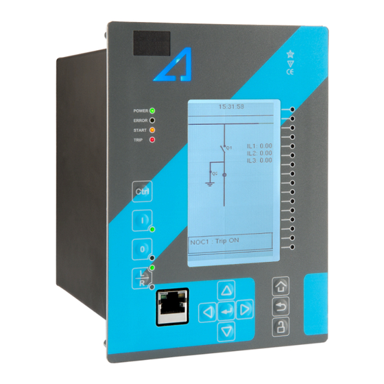
- Page 1 AQ-F210 Feeder protection device...
-
Page 2: Table Of Contents
A A Q Q -F210 -F210 Version: 2.11 Table of contents 1 Document inf 1 Document informa ormation tion ..............................................5 5 1.1 Version 2 revision notes ......................5 1.2 Version 1 revision notes ......................8 1.3 Safety information ........................9 1.4 Abbreviations........................ - Page 3 A A Q Q -F210 -F210 Version: 2.11 4.6.2 Circuit breaker wear monitoring ................236 4.6.3 Current total harmonic distortion (THD) ..............241 4.6.4 Disturbance recorder (DR) ..................246 4.6.5 Event logger ......................256 4.6.6 Measurement recorder .................... 257 4.6.7 Fault register ......................262 5 Communic 5 Communica a tion tion........................
- Page 4 A A Q Q -F210 -F210 Version: 2.11 8.1.3.3 Point sensor arc protection module............. 326 8.1.3.4 Milliampere output module (mA out & mA in) ..........327 8.1.3.5 Milliampere input module (mA out & mA in)..........328 8.1.3.6 RTD input module..................329 8.1.3.7 RS-232 &...
- Page 5 A A Q Q -F210 -F210 Version: 2.11 Disclaimer Please read these instructions carefully before using the equipment or taking any other actions with respect to the equipment. Only trained and qualified persons are allowed to perform installation, operation, service or maintenance of the equipment. Such qualified persons have the responsibility to take all appropriate measures, including e.g.
-
Page 6: Document Inf
A A Q Q -F210 -F210 1 Document information Version: 2.11 1 Document information 1.1 Version 2 revision notes Table. 1.1 - 1. Version 2 revision notes Revision 2.00 Date 6.6.2019 - New more consistent look. - Improved descriptions generally in many chapters. - Improved readability of a lot of drawings and images. - Page 7 A A Q Q -F210 -F210 1 Document information Version: 2.11 - Terminology consistency improved (e.g. binary inputs are now always called digital inputs). - Tech data modified to be more informative about what type of measurement inputs are used (phase currents/voltages, residual currents/voltages), what component of that measurement is available (RMS, TRMS, peak-to-peak) and possible calculated measurement values (powers, impedances, angles etc.).
- Page 8 A A Q Q -F210 -F210 1 Document information Version: 2.11 - Improved descriptions generally in many chapters. - Improved readability of a lot of drawings and images. - Order codes have been revised. - Fixed bias calculation formula for restricted earth fault function. Was correctly in the code, just written wrong in the manual.
-
Page 9: Version 1 Revision Notes
A A Q Q -F210 -F210 1 Document information Version: 2.11 1.2 Version 1 revision notes Table. 1.2 - 2. Version 1 revision notes Revision 1.00 Date 8.4.2013 Changes • The first revision for AQ-F210. Revision 1.01 Date 22.11.2013 • Application example for ARON input connection added to Chapter 8. •... -
Page 10: Safety Information
A A Q Q -F210 -F210 1 Document information Version: 2.11 • Measurement value recorder description. • ZCT connection added to the current measurement description. • Ring-lug CT card option description added. Changes • Order code revised. • Non-standard inverse time delay curves added. •... -
Page 11: Abbreviations
A A Q Q -F210 -F210 1 Document information Version: 2.11 1.4 Abbreviations AI – Analog input AR – Auto-recloser ASDU – Application service data unit AVR – Automatic voltage regulator BCD – Binary-coded decimal CB – Circuit breaker CBFP – Circuit breaker failure protection CLPU –... - Page 12 A A Q Q -F210 -F210 1 Document information Version: 2.11 I/O – Input and output IRIG-B – Inter-range instruction group, timecode B LCD – Liquid-crystal display LED – Light emitting diode LV – Low voltage NC – Normally closed NO –...
-
Page 13: General
A A Q Q -F210 -F210 2 General Version: 2.11 2 General The AQ-F210 feeder protection device is a member of the AQ 200 product line. The hardware and software are modular: the hardware modules are assembled and configured according to the application's I/O requirements and the software determines the available functions. -
Page 14: De 3 Device User Int Vice User Interface Erface
A A Q Q -F210 -F210 3 Device user interface Version: 2.11 3 Device user interface 3.1 Panel structure The user interface section of an AQ 200 or AQ 250 series device is divided into two user interface sections: one for the hardware and the other for the software. You can access the software interface either through the front panel or through the AQtivate 200 freeware software suite. -
Page 15: Mimic And Main Menu
A A Q Q -F210 -F210 3 Device user interface Version: 2.11 When the unit is powered on, the green "Power" LED is lit. When the red "Error" LED is lit, the device has an internal (hardware or software) error that affects the operation of the unit. The activation of the yellow "Start"... -
Page 16: Navigation In The Main Configuration Menus
A A Q Q -F210 -F210 3 Device user interface Version: 2.11 3.2.2 Navigation in the main configuration menus All the settings in this device have been divided into the following six (6) main configuration menus: • General • Protection •... - Page 17 A A Q Q -F210 -F210 3 Device user interface Version: 2.11 Figure. 3.3 - 4. General menu structure. Device info Figure. 3.3 - 5. Device info. © Arcteq Relays Ltd IM00039...
- Page 18 A A Q Q -F210 -F210 3 Device user interface Version: 2.11 Table. 3.3 - 3. Parameters and indications in the General menu. Name Range Step Default Description Device name Unitname The file name uses these fields when loading the .aqs configuration file from the AQ-200 unit.
- Page 19 A A Q Q -F210 -F210 3 Device user interface Version: 2.11 Name Range Step Default Description If the user navigates to a menu and gives no input after a period of time defined with this Return to default view 0…3600 s 10 s parameter, the unit automatically returns to...
-
Page 20: Protection Menu
A A Q Q -F210 -F210 3 Device user interface Version: 2.11 3.4 Protection menu General Figure. 3.4 - 7. Protection menu structure. The Protection main menu includes the Stage activation submenu as well as the submenus for all the various protection functions, categorized under the following modules: "Arc protection", "Current", "Voltage", "Frequency", "Sequence"... - Page 21 A A Q Q -F210 -F210 3 Device user interface Version: 2.11 Figure. 3.4 - 8. Protection menu view. Stage activation You can activate the various protection stages in the Stage activation submenu (see the images below). Each protection stage and supporting function is disabled by default. When you activate one of the stages, its activated menu appears in the stage-specific submenu.
- Page 22 A A Q Q -F210 -F210 3 Device user interface Version: 2.11 Example of a protection stage and its use Once a protection stage has been activated in the Stage activation submenu, you can open its own submenu. In the image series below, the user has activated three current stages. The user accesses the list of activated current stages through the "Current"...
- Page 23 A A Q Q -F210 -F210 3 Device user interface Version: 2.11 The "Info" section offers many details concerning the function and its status: • Function condition: indicates the stage's condition which can be Normal, Start, Trip, or Blocked. • Expected operating time: Expected time delay from detecting a fault to tripping the breaker. This value can vary during a fault if an inverse curve time delay (IDMT) is used.
- Page 24 A A Q Q -F210 -F210 3 Device user interface Version: 2.11 Figure. 3.4 - 13. Registers. Register menu content is not available in the HMI. It can only be accessed with AQtivate setting tool. Stored in the "Registers" section you can find both "Operation event register" and "General event register".
- Page 25 A A Q Q -F210 -F210 3 Device user interface Version: 2.11 Figure. 3.4 - 14. I/O. The "I/O" section is divided into two subsections: "Direct output control" and "Blocking input control". In "Direct output control" you can connect the stage's signals to physical outputs, either to an output relay or an LED (START or TRIP LEDs or one of the 16 user configurable LEDs).
-
Page 26: Control Menu
A A Q Q -F210 -F210 3 Device user interface Version: 2.11 Figure. 3.4 - 15. Events. You can mask on and mask off the protection stage related events in "Event mask". By default events are masked off. You can activate the desired events by masking them ("x"). Remember to save your maskings by confirming the changes with the check mark icon. - Page 27 A A Q Q -F210 -F210 3 Device user interface Version: 2.11 Controls enabled Figure. 3.5 - 17. Controls enabled submenu. You can activate the selected control functions in the Controls enabled submenu. By default all the control functions are disabled. All activated functions can be viewed in the Control functions submenu (see the section "Control functions"...
- Page 28 A A Q Q -F210 -F210 3 Device user interface Version: 2.11 • Used se Used set t ting gr ting groups oups: this setting allows the activation of setting groups SG1...SG8 (only one group is active by default). • SG loc SG local select al select: selects the local control for the different setting groups (can use digital inputs, logical inputs or outputs, RTDs, object status information as well as stage starts, trips or blocks).
- Page 29 A A Q Q -F210 -F210 3 Device user interface Version: 2.11 Figure. 3.5 - 21. Settings section. OBJECT SET AND STATUS • L L oc ocal/R al/Remo emot t e sta e stat t us us: control access may be set to Local or Remote (Local by default; please note that when local control is enabled, the object cannot be controlled through the bus and vice versa).
- Page 30 A A Q Q -F210 -F210 3 Device user interface Version: 2.11 • An object has both Open input Open input and C C lose input lose input signals which are used for indicating the status of the breaker on the HMI and in SCADA. Status can be indicated by any of the following: digital inputs, logical inputs or outputs.
- Page 31 A A Q Q -F210 -F210 3 Device user interface Version: 2.11 Figure. 3.5 - 22. Application control section. You can connect object statuses directly to specific physical outputs in the "Signal connections" subsection ( Control → Application control ). A status can be connected to output relays, as well as to user-configurable LEDs.
- Page 32 A A Q Q -F210 -F210 3 Device user interface Version: 2.11 The "Registers"section stores the function's specific fault data. There are twelve (12) registers, and each of them includes data such as opening and closing times, command types and request failures. The data included in the register depend on the protection function.
- Page 33 A A Q Q -F210 -F210 3 Device user interface Version: 2.11 Each control function that has been activated is listed in the Control functions submenu (see the middle image above). This submenu includes the following sections: "Info", "Settings", "Registers", "I/O" and "Events".
- Page 34 A A Q Q -F210 -F210 3 Device user interface Version: 2.11 The stage settings vary depending on which control function they are a part of. By default only one setting group of the eight available setting groups is activated. You can enable more groups in the Control →...
- Page 35 A A Q Q -F210 -F210 3 Device user interface Version: 2.11 Figure. 3.5 - 29. I/O section. The "I/O" section is divided into two subsections: "Direct output control" and "Blocking input control". In "Direct output control" you can connect the stage's signals to physical outputs, either to an output relay or an LED (START or TRIP LEDs or one of the 16 user configurable LEDs).
- Page 36 A A Q Q -F210 -F210 3 Device user interface Version: 2.11 Figure. 3.5 - 30. Events section. You can mask on and mask off events related to an object's stage in "Event mask". By default all events are masked off. You can activate the desired events by masking them ("x"). Please remember to save your maskings by confirming the changes with the check mark icon.
- Page 37 A A Q Q -F210 -F210 3 Device user interface Version: 2.11 Figure. 3.5 - 32. Digital input section. All settings related to digital inputs can be found in the "Digital inputs" section. The "Digital inputs settings" subsection includes various settings for the inputs: the polarity selection determines whether the input is Normal Open (NO) or Normal Closed (NC) as well as the activation threshold voltage (16…200 V AC/DC, step 0.1 V) and release threshold voltage (10…200 V AC/DC, step 0.1 V) for each available input.
- Page 38 A A Q Q -F210 -F210 3 Device user interface Version: 2.11 The "Digital outputs settings" subsection lets you select the polarity for each output; they can be either Normal Open (NO) or Normal Closed (NC). The default polarity is Normal Open. The operational delay of an output contact is approximately 5 ms.
- Page 39 A A Q Q -F210 -F210 3 Device user interface Version: 2.11 Figure. 3.5 - 35. Device I/O matrix section. Through the "Device I/O matrix" section you can connect digital inputs, logical outputs, protection stage status signals (START, TRIP, BLOCKED, etc.), object status signals and many other binary signals to output relays, or to LEDs configured by the used.
- Page 40 A A Q Q -F210 -F210 3 Device user interface Version: 2.11 Figure. 3.5 - 37. Programmable mimic indicators section. Programmable mimic indicators can be placed into the mimic to display a text based on the status of a given binary signal (digital input, logical signal, status of function start/tripped/blocked signals etc.). When configuring the mimic with the AQtivate 200 setting tool, it is possible to set a text to be shown when an input signal is ON and a separate text for when the signal is OFF.
-
Page 41: Communication Menu
A A Q Q -F210 -F210 3 Device user interface Version: 2.11 GOOSE inputs are mainly used for controlling purposes and in conjunction with the IEC 61850 communication protocol. There are 64 GOOSE inputs signal status bits, and their status can be either 0 or 1. - Page 42 A A Q Q -F210 -F210 3 Device user interface Version: 2.11 Connections Figure. 3.6 - 40. View of the Connections submenu. The Connections submenu offers the following bits of information and settings: ETHERNET ETHERNET This section defines the IP settings for the Ethernet port in the back panel of the unit. •...
- Page 43 A A Q Q -F210 -F210 3 Device user interface Version: 2.11 Protocols Figure. 3.6 - 41. View of the Protocols submenu. The Protocols submenu offers access to the various communication protocol configuration menus. Some of the communication protocols use serial communication and some use Ethernet communication.
-
Page 44: Measurement Menu
A A Q Q -F210 -F210 3 Device user interface Version: 2.11 3.7 Measurement menu Figure. 3.7 - 42. Measurement section. The Measurement menu includes the following submenus: Transformers , Frequency , Current measurement , Voltage measurement , Power and energy measurement , Impedance calculations , and Phasors . - Page 45 A A Q Q -F210 -F210 3 Device user interface Version: 2.11 CT module Figure. 3.7 - 44. CT module section. The three main sections ("Phase CT scaling", "Residual I01 CT scaling" and "Residual I02 CT scaling") determine the ratio of the used transformers. Additionally, the nominal values are also determined in the CT module submenu.
- Page 46 A A Q Q -F210 -F210 3 Device user interface Version: 2.11 Frequency measurements use the fixed sampling mode as the default, and "System nominal frequency" should be set to the desired level. When "Sampling mode" is set to "Tracking", the device uses the measured frequency value as the system nominal frequency.
-
Page 47: Monitoring Menu
A A Q Q -F210 -F210 3 Device user interface Version: 2.11 Phasors Figure. 3.7 - 47. Phasors submenu. The Phasors submenu holds the vector displays for voltages and currents, as well as the various calculated components the device may have (e.g. power, impedance). Phasors are helpful when solving incorrect wiring issues. - Page 48 A A Q Q -F210 -F210 3 Device user interface Version: 2.11 Monitors enabled Figure. 3.8 - 49. Monitors enabled submenu. You can activate the selected monitor functions in the Monitors enabled submenu. By default all the control functions are disabled. All activated functions can be viewed in the Monitor functions submenu (see the section "Monitor functions"...
- Page 49 A A Q Q -F210 -F210 3 Device user interface Version: 2.11 Disturbance recorder Figure. 3.8 - 51. Disturbance recorder settings. The Disturbance recorder submenu has the following settings: • "Recorder enabled" enables or disables the recorder. • "Recorder status" indicates the status of the recorder. •...
-
Page 50: Configuring User Levels And Their Passwords
A A Q Q -F210 -F210 3 Device user interface Version: 2.11 • Enabling "Auto. get recordings" allows the device to automatically upload recordings to the designated FTP folder (which, in turn, allows any FTP client to read the recordings from the device's memory). - Page 51 A A Q Q -F210 -F210 3 Device user interface Version: 2.11 A number of stars are displayed in the upper right corner of the HMI; these indicate the current user level. The different user levels and their star indicators are as follows (also, see the image below for the HMI view): •...
- Page 52 A A Q Q -F210 -F210 3 Device user interface Version: 2.11 • User: Can view any menus and settings but cannot change any settings, nor operate breakers or other equipment. • Operator: Can view any menus and settings but cannot change any settings BUT can operate breakers and other equipment.
-
Page 53: Functions Unctions
A A Q Q -F210 -F210 4 Functions Version: 2.11 4 Functions 4.1 Functions included in AQ-F210 The AQ-F210 feeder protection device includes the following functions as well as the number of stages in those functions. Table. 4.1 - 4. Protection functions of AQ-F210. Name (number ANSI Description... -
Page 54: Measurements
A A Q Q -F210 -F210 4 Functions Version: 2.11 Name ANSI Description CLPU CLPU Cold load pick-up SOTF SOTF Switch-on-to-fault 0 → 1 Auto-recloser Programmable control switch mA output Milliampere output control Table. 4.1 - 6. Monitoring functions of AQ-F210. Name ANSI Description... - Page 55 A A Q Q -F210 -F210 4 Functions Version: 2.11 Figure. 4.2.1 - 53. Current measurement terminology. P P RI: RI: The primary current, i.e. the current which flows in the primary circuit and through the primary side of the current transformer. SEC: SEC: The secondary current, i.e.
- Page 56 A A Q Q -F210 -F210 4 Functions Version: 2.11 The device calculates the scaling factors based on the set values of the CT primary, the CT secondary and the nominal current settings. The device measures the secondary current, the current output from the current transformer installed into application's primary circuit.
- Page 57 A A Q Q -F210 -F210 4 Functions Version: 2.11 • The phase currents are connected to the I01 residual via a Holmgren connection. • The starpoint of the phase current CT's secondary current is towards the line. Phase CT scaling Next, to scale the current to per-unit values, we have to select whether the basis of the phase CT scaling is the protected object's nominal current or the CT primary value.
- Page 58 A A Q Q -F210 -F210 4 Functions Version: 2.11 Once the measurement scaling is tied to the protected object's nominal current, the user must set the appropriate input for the "Nominal current In" setting. One can now see the differences between the two scaling options (CT nominal vs.
- Page 59 A A Q Q -F210 -F210 4 Functions Version: 2.11 Figure. 4.2.1 - 59. Scalings display (based on the CT nominal). Figure. 4.2.1 - 60. Scalings display (based on the protected object's nominal current). As the images above show, the scaling selection does not affect how primary and secondary currents are displayed (as actual values).
- Page 60 A A Q Q -F210 -F210 4 Functions Version: 2.11 Figure. 4.2.1 - 61. Connections of ZCT scaling. Troubleshooting When the measured current values differ from the expected current values, the following table offers possible solutions for the problems. W W ARNING! ARNING! If you work with energized CTs, extreme caution needs to be taken when checking the connections! An opened CT secondary circuit may generate dangerously high voltages.
- Page 61 A A Q Q -F210 -F210 4 Functions Version: 2.11 Problem Solution The phase currents are connected to the measurement module but the order or polarity of one or all phases is incorrect. In device settings, go to Measurement → Phasors and check the "Phase current vectors"...
- Page 62 A A Q Q -F210 -F210 4 Functions Version: 2.11 Figure. 4.2.1 - 62. Common phase polarity problems. The following image presents the most common problems with network rotation (mix phases). These problems can be difficult to find because the measurement result is always the same in the device. If two phases are mixed together, the network rotation always follows the pattern IL1-IL3-IL2 and the measured negative sequence current is therefore always 1.00 (in.
- Page 63 A A Q Q -F210 -F210 4 Functions Version: 2.11 Figure. 4.2.1 - 63. Common network rotation (mixed phases) problems. Settings Table. 4.2.1 - 8. Settings of the Phase CT scaling. Name Range Step Default Description Scale • CT nom p.u. •...
- Page 64 A A Q Q -F210 -F210 4 Functions Version: 2.11 Name Range Step Default Description A feedback value; the calculated scaling factor that is the ratio between the set primary current and the set CT scaling nominal current. This parameter is only visible if the factor NOM option "Object In p.u."...
- Page 65 A A Q Q -F210 -F210 4 Functions Version: 2.11 Table. 4.2.1 - 11. Per-unit phase current measurements. Name Unit Range Step Description Phase current 0.000…1 The current fundamental frequency component (in p.u.) × In 0.001 250.000 from each of the phase current channels. ("Pha.curr.ILx") Phase current ILx TRMS...
- Page 66 A A Q Q -F210 -F210 4 Functions Version: 2.11 Table. 4.2.1 - 15. Per-unit residual current measurements. Name Unit Range Step Description The current measurement fundamental frequency Residual current I0x 0.00…1 × In 0.01 component (in p.u.) from the residual current channel I01 ("Res.curr.I0x") 250.00 or I02.
- Page 67 A A Q Q -F210 -F210 4 Functions Version: 2.11 Table. 4.2.1 - 18. Residual phase angle measurements. Name Unit Range Step Description Residual current angle I0x The residual current angle measurement from the I01 or 0.00…360.00 0.01 ("Res.curr.angle I02 current input. I0x") calc.I0 Pha.angle 0.00…360.00 0.01 The calculated residual current angle measurement.
- Page 68 A A Q Q -F210 -F210 4 Functions Version: 2.11 Name Unit Range Step Description Secondary zero sequence current The secondary measurement from the calculated 0.00…300.00 0.01 ("Sec.Zero sequence zero sequence current. curr.") Table. 4.2.1 - 22. Sequence phase angle measurements. Name Unit Range...
-
Page 69: Frequency Tracking And Scaling
A A Q Q -F210 -F210 4 Functions Version: 2.11 4.2.2 Frequency tracking and scaling Measurement sampling can be set to the frequency tracking mode or to the fixed user- defined frequency sampling mode. The benefit of frequency tracking is that the measurements are within a pre-defined accuracy range even when the fundamental frequency of the power system changes. - Page 70 A A Q Q -F210 -F210 4 Functions Version: 2.11 Problem Check / Resolution The measured current or voltage amplitude is The set system frequency may be wrong. Please check that the frequency settings lower than it should match the local system frequency, or change the measurement mode to "Tracking" be./ ( Measurement →...
- Page 71 A A Q Q -F210 -F210 4 Functions Version: 2.11 Name Range Step Default Description • None • CT1IL3 Frequency • CT2IL3 CT1IL3 The third reference source for frequency tracking. reference 3 • VT1U3 • VT2U3 • No trackable channels •...
-
Page 72: General Menu
A A Q Q -F210 -F210 4 Functions Version: 2.11 Name Range Step Default Description Frequency measurement value used by protection f.atm. functions. When frequency is not measurable this 0.000…75.000Hz 0.001Hz - Protections value returns to value set to "System nominal frequency"... - Page 73 A A Q Q -F210 -F210 4 Functions Version: 2.11 Table. 4.3 - 27. Parameters and indications in the General menu. Name Range Default Description Device name Unitname The file name uses these fields when loading the .aqs configuration file from the AQ-200 unit. Device location Unitlocation •...
-
Page 74: Protection Functions
A A Q Q -F210 -F210 4 Functions Version: 2.11 Name Range Default Description • OBJ1 • OBJ2 • OBJ3 • OBJ4 "I" and "0" push buttons on the front panel of the I/0 default object • OBJ5 device have an indication LED. This parameter defines OBJ1 selection •... - Page 75 A A Q Q -F210 -F210 4 Functions Version: 2.11 Table. 4.4.1 - 29. Measurement inputs of the I> function. Signal Description Time base Fundamental frequency component of phase L1 (A) current measurement Fundamental frequency component of phase L2 (B) current measurement Fundamental frequency component of phase L3 (C) current measurement TRMS TRMS measurement of phase L1 (A) current...
- Page 76 A A Q Q -F210 -F210 4 Functions Version: 2.11 Pick-up settings The I setting parameter controls the pick-up of the I> function. This defines the maximum allowed measured current before action from the function. The function constantly calculates the ratio between the I and the measured magnitude ( I ) for each of the three phases.
- Page 77 A A Q Q -F210 -F210 4 Functions Version: 2.11 Name Range Step Description meas The ratio between the highest measured phase current and the 0.00...1250.00 0.01 at the pick-up value. moment Function blocking The block signal is checked in the beginning of each program cycle. The blocking signal is received from the blocking matrix in the function's dedicated input.
- Page 78 A A Q Q -F210 -F210 4 Functions Version: 2.11 Event block name Event names NOC1...NOC4 Trip ON NOC1...NOC4 Trip OFF NOC1...NOC4 Block ON NOC1...NOC4 Block OFF NOC1...NOC4 Phase A Start ON NOC1...NOC4 Phase A Start OFF NOC1...NOC4 Phase B Start ON NOC1...NOC4 Phase B Start OFF NOC1...NOC4...
-
Page 79: Non-Directional Earth Fault Protection (I0>; 50N/51N)
A A Q Q -F210 -F210 4 Functions Version: 2.11 4.4.2 Non-directional earth fault protection (I0>; 50N/51N) The non-directional earth fault function is used for instant and time-delayed earth fault protection. The number of stages in the function depend on the device model. The operating characteristics are based on the selected neutral current magnitude which the function measures constantly. - Page 80 A A Q Q -F210 -F210 4 Functions Version: 2.11 Table. 4.4.2 - 37. General settings of the function. Name Range Default Description Setting • Disabled Activating this parameter permits changing the pick-up level of the control from Disabled • Allowed protection stage via SCADA.
- Page 81 A A Q Q -F210 -F210 4 Functions Version: 2.11 Name Range Step Description Angle of I0 against reference. If phase voltages are available, Detected 0.01 positive sequence voltage angle is used as reference. If voltages -360.00...360.00 deg I0 angle are not available, positive sequence current angle is used as reference.
- Page 82 A A Q Q -F210 -F210 4 Functions Version: 2.11 Operating time characteristics for trip and reset This function supports definite time delay (DT) and inverse definite minimum time delay (IDMT). For detailed information on these delay types please refer to the chapter "General properties of a protection function"...
-
Page 83: Negative Sequence Overcurrent/ Phase Current Reversal/ Current Unbalance Protection (I2>; 46/46R/46L)
A A Q Q -F210 -F210 4 Functions Version: 2.11 4.4.3 Negative sequence overcurrent/ phase current reversal/ current unbalance protection (I2>; 46/46R/46L) The current unbalance function is used for instant and time-delayed unbalanced network protection and for detecting broken conductors. The number of stages in the function depends on the device model. - Page 84 A A Q Q -F210 -F210 4 Functions Version: 2.11 Signal Description Time base Fundamental frequency component of phase L1 (A) current measurement 5 ms Fundamental frequency component of phase L2 (B) current measurement 5 ms Fundamental frequency component of phase L3 (C) current measurement 5 ms General settings The following general settings define the general behavior of the function.
- Page 85 A A Q Q -F210 -F210 4 Functions Version: 2.11 Table. 4.4.3 - 46. Information displayed by the function. Name Range Description Normal Start I2> condition Displays the status of the protection function. Trip Blocked Function blocking The block signal is checked in the beginning of each program cycle. The blocking signal is received from the blocking matrix in the function's dedicated input.
- Page 86 A A Q Q -F210 -F210 4 Functions Version: 2.11 Figure. 4.4.3 - 67. Operation characteristics curve for I2> Curve2. For a more detailed description on the time characteristics and their setting parameters, please refer to the "General properties of a protection function" chapter and its "Operating time characteristics for trip and reset"...
-
Page 87: Harmonic Overcurrent Protection (Ih>; 50H/51H/68H)
A A Q Q -F210 -F210 4 Functions Version: 2.11 Event block name Event names CUB1...CUB4 Block OFF The function registers its operation into the last twelve (12) time-stamped registers. The register of the function records the ON event process data for START, TRIP or BLOCKED. The table below presents the structure of the function's register content. - Page 88 A A Q Q -F210 -F210 4 Functions Version: 2.11 Figure. 4.4.4 - 68. Simplified function block diagram of the Ih> function. Measured input The function block uses analog current measurement values from phase or residual currents. Each measurement input of the function block uses RMS (fundamental frequency component) values and harmonic components of the selected current input.
- Page 89 A A Q Q -F210 -F210 4 Functions Version: 2.11 Signal Description Time base The magnitudes (RMS) of phase L2 (B) current components: - Fundamental harmonic harmonic harmonic harmonic harmonic 5 ms harmonic harmonic - 11 harmonic - 13 harmonic - 15 harmonic - 17...
- Page 90 A A Q Q -F210 -F210 4 Functions Version: 2.11 Signal Description Time base The magnitudes (RMS) of residual I0 current components: - Fundamental harmonic harmonic harmonic harmonic harmonic 5 ms harmonic harmonic - 11 harmonic - 13 harmonic - 15 harmonic - 17 harmonic...
- Page 91 A A Q Q -F210 -F210 4 Functions Version: 2.11 Name Range Default Description • 2 harmonic • 3 harmonic • 4 harmonic • 5 harmonic • 6 harmonic • 7 Harmonic harmonic Selection of the monitored harmonic component. selection harmonic •...
- Page 92 A A Q Q -F210 -F210 4 Functions Version: 2.11 Name Range Step Default Description Pick-up setting Ih/IL 5.00…200.00% 0.01% 20.00% (percentage monitoring) Read-only parameters The function's Info page displays useful, real-time information on the state of the protection function. It is accessed either through the device's HMI display, or through the setting tool software when it is connected to the device and its Live Edit mode is active.
- Page 93 A A Q Q -F210 -F210 4 Functions Version: 2.11 Events and registers The harmonic overcurrent function (abbreviated "HOC" in event block names) generates events and registers from the status changes in the events listed below. The user can select which event messages are stored in the main event buffer: ON, OFF, or both.
-
Page 94: Circuit Breaker Failure Protection (Cbfp; 50Bf/52Bf)
A A Q Q -F210 -F210 4 Functions Version: 2.11 4.4.5 Circuit breaker failure protection (CBFP; 50BF/52BF) The circuit breaker failure protection function is used for monitoring the circuit breaker operation after it has received a TRIP signal. The function can also be used to retrip a failing breaker; if the retrip fails, an incoming feeder circuit breaker can be tripped by using the function's CBFP output. - Page 95 A A Q Q -F210 -F210 4 Functions Version: 2.11 Signal Description Time base Fundamental frequency component of residual input I measurement Calculated residual current from the phase current inputs 0Calc General settings The following general settings define the general behavior of the function. These settings are static i.e. it is not possible to change them by editing the setting group.
- Page 96 A A Q Q -F210 -F210 4 Functions Version: 2.11 Table. 4.4.5 - 58. Operating mode and input signals selection. Name Range Step Default Description • Not in Selects the residual current monitoring source, which can be Not in I0Input •...
- Page 97 A A Q Q -F210 -F210 4 Functions Version: 2.11 Table. 4.4.5 - 60. Information displayed by the function. Name Range Description • Normal • Start CBFP condition • ReTrip Displays status of the protection function. • CBFP On • Blocked Function blocking The block signal is checked in the beginning of each program cycle.
- Page 98 A A Q Q -F210 -F210 4 Functions Version: 2.11 Trip, Retrip and CBFP in the device configuration Figure. 4.4.5 - 70. Wiring diagram when Trip, Retrip and CBFP are configured to the device. The retrip functionality can be used in applications whose circuit breaker has a retrip or a redundant trip coil available.
- Page 99 A A Q Q -F210 -F210 4 Functions Version: 2.11 Figure. 4.4.5 - 71. Retrip and CBFP when "Current" is the selected criterion. When the current threshold setting of I and/or I0 is exceeded, the current-based protection is activated and the counters for RETRIP and CBFP start calculating the set operating time. The tripping of the primary protection stage is not monitored in this configuration.
- Page 100 A A Q Q -F210 -F210 4 Functions Version: 2.11 Figure. 4.4.5 - 72. Retrip and CBFP when "Current and DO" is the selected criterion. When the current threshold setting of I and/or I0 is exceeded, the current-based protection is activated.
- Page 101 A A Q Q -F210 -F210 4 Functions Version: 2.11 Figure. 4.4.5 - 73. Retrip and CBFP when "Current or DO" is the selected criterion. When the current threshold setting of I and/or I0 is exceeded, or the TRIP signal reaches the primary protection stage, the function starts counting down towards the RETRIP and CBFP signals.
- Page 102 A A Q Q -F210 -F210 4 Functions Version: 2.11 Trip and CBFP in the device configuration Figure. 4.4.5 - 74. Wiring diagram when Trip and CBFP are configured to the device. Probably the most common application is when the device's trip output controls the circuit breaker trip coil, while one dedicated CBFP contact controls the CBFP function.
- Page 103 A A Q Q -F210 -F210 4 Functions Version: 2.11 Figure. 4.4.5 - 75. CBFP when "Current" is the selected criterion. When the current threshold setting of I and/or I0 is exceeded, the current-based protection is activated and the counter for CBFP starts calculating the set operating time. The tripping of the primary protection stage is not monitored in this configuration.
- Page 104 A A Q Q -F210 -F210 4 Functions Version: 2.11 Figure. 4.4.5 - 76. CBFP when "Current and DO" is the selected criterion. When the current threshold setting of I and/or I0 is exceeded, the current-based protection is activated. At the same time, the counter for CBFP is halted until the monitored output contact is controlled (that is, until the primary protection operates).
- Page 105 A A Q Q -F210 -F210 4 Functions Version: 2.11 Figure. 4.4.5 - 77. CBFP when "Current or DO" is the selected criterion. When the current threshold setting of I and/or I0 is exceeded, or the TRIP signal reaches the primary protection stage, the function starts counting down towards the CBFP signal.
- Page 106 A A Q Q -F210 -F210 4 Functions Version: 2.11 Device configuration as a dedicated CBFP unit Figure. 4.4.5 - 78. Wiring diagram when the device is configured as a dedicated CBFP unit. © Arcteq Relays Ltd IM00039...
- Page 107 A A Q Q -F210 -F210 4 Functions Version: 2.11 Some applications require a dedicated circuit breaker protection unit. When the CBFP function is configured to operate with a digital input signal, it can be used in these applications. When a device is used for this purpose, the tripping signal is wired to the device's digital input and the device's own TRIP signal is used only for the CBFP purpose.
- Page 108 A A Q Q -F210 -F210 4 Functions Version: 2.11 Event block name Event names CBF1 Retrip ON CBF1 Retrip OFF CBF1 CBFP ON CBF1 CBFP OFF CBF1 Block ON CBF1 Block OFF CBF1 DO monitor ON CBF1 DO monitor OFF CBF1 Signal ON CBF1...
-
Page 109: Low-Impedance Or High-Impedance Restricted Earth Fault/ Cable End Differential Protection (I0D>; 87N)
A A Q Q -F210 -F210 4 Functions Version: 2.11 4.4.6 Low-impedance or high-impedance restricted earth fault/ cable end differential protection (I0d>; 87N) The low-impedance or high-impedance restricted earth fault function is used for residual differential current measurement for transformers. This function can also be used as the cable end differential function. - Page 110 A A Q Q -F210 -F210 4 Functions Version: 2.11 Signal Description Time base Angle of phase L2 (B) current Angle of phase L3 (C) current Angle of residual input I01 Angle of residual input I02 General settings The following general settings define the general behavior of the function. These settings are static i.e. it is not possible to change them by editing the setting group.
- Page 111 A A Q Q -F210 -F210 4 Functions Version: 2.11 Name Range Step Default Description • Residual Selection of the bias current calculation. Differential current (3I0 Bias characteristics biasing can use either the calculated residual + I0Calc)/2 Residual current current averages or the maximum of all measured currents. •...
- Page 112 A A Q Q -F210 -F210 4 Functions Version: 2.11 Figure. 4.4.6 - 83. Differential characteristics for the I0d> function with default settings. The equations for the differential characteristics are the following: Figure. 4.4.6 - 84. Differential current (the calculation is based on user-selected inputs and direction). Figure.
- Page 113 A A Q Q -F210 -F210 4 Functions Version: 2.11 Read-only parameters The function's Info page displays useful, real-time information on the state of the protection function. It is accessed either through the device's HMI display, or through the setting tool software when it is connected to the device and its Live Edit mode is active.
- Page 114 A A Q Q -F210 -F210 4 Functions Version: 2.11 Figure. 4.4.6 - 87. Cable end differential with natural unbalance in the phase current measurement. When calculating residual current from the phase currents, the natural unbalance can be around 10 % while the used CTs are still within the promised 5P class (which is probably the most common CT accuracy class).
- Page 115 A A Q Q -F210 -F210 4 Functions Version: 2.11 Figure. 4.4.6 - 88. Cable end differential when a fault occurs. If a starting fault occurs in the cable end, the CED mode catches the difference between the ingoing and the outgoing residual currents. The resulting signal can be used for alarming or tripping purposes for the feeder with the failing cable end.
- Page 116 A A Q Q -F210 -F210 4 Functions Version: 2.11 Figure. 4.4.6 - 89. Restricted earth fault outside a Y winding transformer. If the fault is located inside of the transformer and thus inside of the protection area, the function catches the fault with high sensitivity.
- Page 117 A A Q Q -F210 -F210 4 Functions Version: 2.11 Figure. 4.4.6 - 90. Restricted earth fault inside a Y winding transformer. Events and registers The restricted earth fault function (abbreviated "REF" in event block names) generates events and registers from the status changes in the events listed below. The user can select which event messages are stored in the main event buffer: ON, OFF, or both.
-
Page 118: Line Thermal Overload Protection (Tf>; 49F)
A A Q Q -F210 -F210 4 Functions Version: 2.11 Table. 4.4.6 - 68. Event messages. Event block name Event names REF1 I0d> (87N) Trip ON REF1 I0d> (87N) Trip OFF REF1 I0d> (87N) Block ON REF1 I0d> (87N) Block OFF The function registers its operation into the last twelve (12) time-stamped registers. - Page 119 A A Q Q -F210 -F210 4 Functions Version: 2.11 Where: • θ = Thermal image status in percentages of the maximum thermal capacity available • θ = Thermal image status in a previous calculation cycle (the memory of the function) •...
- Page 120 A A Q Q -F210 -F210 4 Functions Version: 2.11 Figure. 4.4.7 - 91. Example of thermal image calculation with nominal conditions. The described behavior is based on the assumption that the monitored object (whether a cable, a line or an electrical device) has a homogenous body which generates and dissipates heat with a rate proportional to the temperature rise caused by the current squared.
- Page 121 A A Q Q -F210 -F210 4 Functions Version: 2.11 Where: • t = Measured (or set) ambient temperature (can be set in ̊ C or in ̊ F ) • t = Maximum temperature (can be set in ̊ C or in ̊ F ) for the protected object •...
- Page 122 A A Q Q -F210 -F210 4 Functions Version: 2.11 Figure. 4.4.7 - 93. Example of the relationship between ground temperature and correction factor. The temperature coefficient may be informed in a similar manner to the figure above in a datasheet provided by the manufacturer.
- Page 123 A A Q Q -F210 -F210 4 Functions Version: 2.11 Figure. 4.4.7 - 95. Set correction curve for ambient temperature. The correction curve for ambient temperature is shown in the figure above. The reference temperature for underground cables is usually +15 ̊ C which gives a correction factor of 1.00 (in this case also the nominal temerature).
- Page 124 A A Q Q -F210 -F210 4 Functions Version: 2.11 Figure. 4.4.7 - 96. Example of a high-voltage cable datasheet. The datasheet shows the currents which in a combination with a specific installation and a specific construction method achieve a specific conductor temperature in give standard conditions (e.g. a copper conductor reaches a temperature of 90 °C when, for example, it has a continuous current- carrying capacity of 815 A, an open screen circuit, and is laid in a trefoil formation in soil whose temperature is 15 °C).
- Page 125 A A Q Q -F210 -F210 4 Functions Version: 2.11 Figure. 4.4.7 - 97. General presumptions of high-voltage cables. If the installation conditions vary from the presumed conditions manufacturers may give additional information on how to correct the the current-carrying capacity to match the changed conditions. Below is an example of the correction factors provided a manufacturer (Prysmian) for correcting the current-carrying capacity.
- Page 126 A A Q Q -F210 -F210 4 Functions Version: 2.11 Figure. 4.4.7 - 98. Example of correction factors for the current-carrying capacity as given by a manufacturer. © Arcteq Relays Ltd IM00039...
- Page 127 A A Q Q -F210 -F210 4 Functions Version: 2.11 To demonstrate the importance of the k (service factor, current-carrying capacity), let us calculate a cable installation with the correct k factor but without setting it to correct value. First we read the initial data for the setup of the thermal image: A 66 kV copper cable with a cross-section of 500 mm is installed into ground.
- Page 128 A A Q Q -F210 -F210 4 Functions Version: 2.11 Figure. 4.4.7 - 99. Thermal image response with nominal load (installation according to presumptions). As the results show, the end temperature of 68.39 ̊ C is reached when the cable is loaded with a stable current for time equalling five times the time constant τ.
- Page 129 A A Q Q -F210 -F210 4 Functions Version: 2.11 Figure. 4.4.7 - 100. Thermal image response with maximum load (installation according presumptions). The maximum allowed load results in the end temperature of 89.68 ̊ C which means that 99.57 % of the thermal capacity is used.
- Page 130 A A Q Q -F210 -F210 4 Functions Version: 2.11 Therefore, the settings are as follows: • I = 680 A • T = 90 ̊ C • T = 15 ̊ C • T = 15 ̊ C • τ = 183.8 min •...
- Page 131 A A Q Q -F210 -F210 4 Functions Version: 2.11 Figure. 4.4.7 - 102. Thermal response with k factor correctly set. When the installation conditions vary from the presumptive conditions, the cable's current-carrying capacity can be reduced so that the temperature of 90 ̊ C is achieved with a 550 A current instead of the 680 A current given in the initial data.
- Page 132 A A Q Q -F210 -F210 4 Functions Version: 2.11 θ = (I meas Where: • I = the measured current meas • I = the calculated effective nominal current Calcula Calculat t ed time constant: ed time constant: (-0.005[s]×(Tc[min]×60)[s]) τ=e Where: •...
- Page 133 A A Q Q -F210 -F210 4 Functions Version: 2.11 Figure. 4.4.7 - 103. Simplified function block diagram of the TF> function. Measured input The function block uses phase current measurement values. The function block uses TRMS values from the whole harmonic specter of 32 components. RTD input can be used for measuring ambient temperature.
- Page 134 A A Q Q -F210 -F210 4 Functions Version: 2.11 Table. 4.4.7 - 72. Settings for thermal replica. Name Range Step Default Description The current for the 100 % thermal capacity to be used (the thermal 0.10…40.00xI 0.01xI 1.00xI pick-up current in p.u., with t achieved in time τ...
- Page 135 A A Q Q -F210 -F210 4 Functions Version: 2.11 Name Range Step Default Description Ambient • Manual set Manual The selection of whether fixed or measured ambient temp. sel. • RTD temperature is used for the thermal image biasing. The manual fixed ambient temperature setting for the Man.
- Page 136 A A Q Q -F210 -F210 4 Functions Version: 2.11 Name Range Step Default Description The selection of whether or not the curve temperature/ coefficient pair is in use. The minimum number to be set for the temperature/coefficient curve is two pairs and the maximum is ten pairs.
- Page 137 A A Q Q -F210 -F210 4 Functions Version: 2.11 Name Range Step Default Description TF> The trip signal's additional delay. This delay delays the trip Trip 0.000…3600.000s 0.005s 0.000s signal generation by a set time. The default setting is 0.000 s delay which does not give an added time delay for the trip signal.
- Page 138 A A Q Q -F210 -F210 4 Functions Version: 2.11 Name Range Description • Nominal current calc TF> • Nominal Indicates if nominal current calculation is set wrong and actually used setting is Setting current set 1.0. Visible only when there is a setting fault. alarm fault.
- Page 139 A A Q Q -F210 -F210 4 Functions Version: 2.11 Name Description / values Restart inhibits The number of times the function has activated the Restart inhibit output Trips The number of times the function has tripped Trips Blocked The number of times the function trips has been blocked Events and registers The line thermal overload protection function (abbreviated "TOLF"...
-
Page 140: Resistance Temperature Detectors (Rtd)
A A Q Q -F210 -F210 4 Functions Version: 2.11 Name Description Active meas. current T at a given moment Max. temp. rise allowed degrees Temp. rise at a given moment degrees Hot spot estimate degrees Hot spot maximum allowed degrees Trip delay rem. - Page 141 A A Q Q -F210 -F210 4 Functions Version: 2.11 Settings Setting up an RTD measurement, the user first needs to set the measurement module to scan the wanted RTD elements. A multitude of Modbus-based modules are supported. Communication requires bitrate, databits, parity, stopbits and Modbus I/O protocol to be set;...
- Page 142 A A Q Q -F210 -F210 4 Functions Version: 2.11 Name Range Step Default Description Displays the measured sensor's data validity. If the sensor reading has any • Ok S1...S16 sensor problems, the sensor data is set to • Invalid "Invalid"...
-
Page 143: Programmable Stage (Pgx>/<; 99)
A A Q Q -F210 -F210 4 Functions Version: 2.11 4.4.9 Programmable stage (PGx>/<; 99) The programmable stage is a stage that the user can program to create more advanced applications, either as an individual stage or together with programmable logic. The device has ten programmable stages, and each can be set to follow one to three analog measurements. - Page 144 A A Q Q -F210 -F210 4 Functions Version: 2.11 Name Description ILx TRMS ILx TRMS value (in p.u.) ILx Ang ILx Angle (degrees) Table. 4.4.9 - 83. Other current measurements Name Description I0Z Mag Zero sequence current value (in p.u.) I0CALC Mag Calculated I0 value (in p.u.) I1 Mag...
- Page 145 A A Q Q -F210 -F210 4 Functions Version: 2.11 Name Description UL31Ang UL31 angle (degrees) UL1Ang UL1 angle (degrees) UL2Ang UL2 angle (degrees) UL3Ang UL3 angle (degrees) U0Ang UL0 angle (degrees) U0CalcMag Calculated residual voltage U1 pos.seq.V Mag Positive sequence voltage U2 neg.seq.V Mag Negative sequence voltage U0CalcAng...
- Page 146 A A Q Q -F210 -F210 4 Functions Version: 2.11 Name Description XLxSec Reactance X L12, L23, L31, L1, L2, L3 secondary (Ω) ZLxSec Impedance Z L12, L23, L31, L1, L2, L3 secondary (Ω) ZLxAngle Impedance Z L12, L23, L31, L1, L2, L3 angle Table.
- Page 147 A A Q Q -F210 -F210 4 Functions Version: 2.11 Name Description Y0Sec Admittance Y0 secondary (mS) Y0Angle Admittance Y0 angle Table. 4.4.9 - 90. Other measurements Name Description System f. System frequency Ref f1 Reference frequency 1 Ref f2 Reference frequency 2 M Thermal T Motor thermal temperature...
- Page 148 A A Q Q -F210 -F210 4 Functions Version: 2.11 Table. 4.4.9 - 91. Information displayed by the function. Name Range Description • Normal • Start Condition Displays status of the function. • Trip • Blocked Expected operating -1800.000...1800.000s Displays the expected operating time when a fault occurs. time When the function has detected a fault and counts down time Time remaining to...
- Page 149 A A Q Q -F210 -F210 4 Functions Version: 2.11 Name Range Step Default Description PS# Pick-up -5 000 setting 000.0000…5 000 0.0001 0.01 Pick-up magnitude Mag#/calc >/< 000.0000 PS# Setting 0.0000…50.0000% 0.0001% 3% Setting hysteresis hysteresis Mag# Definite operating time 0.000…1800.000s 0.005s 0.04s...
- Page 150 A A Q Q -F210 -F210 4 Functions Version: 2.11 Function blocking The block signal is checked in the beginning of each program cycle. The blocking signal is received from the blocking matrix in the function's dedicated input. If the blocking signal is not activated when the pick-up element activates, a START signal is generated and the function proceeds to the time characteristics calculation.
-
Page 151: Arc Fault Protection (Iarc>/I0Arc>; 50Arc/50Narc)
A A Q Q -F210 -F210 4 Functions Version: 2.11 Register Description Trip time remaining 0 ms...1800s Setting group in use Setting group 1...8 active 4.4.10 Arc fault protection (IArc>/I0Arc>; 50Arc/50NArc) Arc faults occur for a multitude of reasons: e.g. insulation failure, incorrect operation of the protected device, corrosion, overvoltage, dirt, moisture, incorrect wiring, or even because of aging caused by electric load. - Page 152 A A Q Q -F210 -F210 4 Functions Version: 2.11 Outputs Activation condition Channel 1 Pressure Channel 2 Pressure The arc protection card's sensor channel detects pressure. Channel 3 Pressure Channel 4 Pressure ARC Binary input The arc protection card's binary input is energized. signal I/I0 Arc>...
- Page 153 A A Q Q -F210 -F210 4 Functions Version: 2.11 • measured and pre-processed current magnitudes. The function's outputs are TRIP, BLOCKED, light sensing etc. signals which can be used for direct I/O controlling and user logic programming. The function generates general time-stamped ON/OFF events to the common event buffer from each of the 26 output signals.
- Page 154 A A Q Q -F210 -F210 4 Functions Version: 2.11 To set the zones for the AQ-200 models sensor channels start by enabling the protected zones (in this case, Zones 1 and 2). Then define which sensor channels are sensing which zones (in this case, sensor channels S1 and S2 are protecting Zone 1).
- Page 155 A A Q Q -F210 -F210 4 Functions Version: 2.11 If any of the channels have a pressure sensing sensor, enable it the same way as the regular light sensors. If either phase overcurrent or residual overcurrent is needed for the tripping decision, they can be enabled in the same way as light sensors in the zone.
- Page 156 A A Q Q -F210 -F210 4 Functions Version: 2.11 Name Range Default Description Channel sensors Channel sensors Channel sensors Channel sensor status Channel sensor Displays the status of the sensor channel. If the number of sensors status • Sensors OK connected to the channel does not match with the set "Channel 1/2/3/ •...
- Page 157 A A Q Q -F210 -F210 4 Functions Version: 2.11 Name Range Step Default Description Zone1/2/3/ • Disabled The phase overcurrent allows the zone to trip when light is 4 Ph. curr. Disabled • Enabled detected. Enabled Zone1/2/3/ • Disabled The residual overcurrent allows the zone to trip when light is 4 Res.
- Page 158 A A Q Q -F210 -F210 4 Functions Version: 2.11 • Z1 Trip • Z1 Blocked • Z2 Trip • Z2 Blocked I/I0 Arc> condition Displays status of the protection function. • Z3 Trip • Z3 Blocked • Z4 Trip •...
- Page 159 A A Q Q -F210 -F210 4 Functions Version: 2.11 Event block name Event names ARC1 Zone 1...4 Block ON ARC1 Zone 1...4 Block OFF ARC1 Phase current Blocked ON ARC1 Phase current Blocked OFF ARC1 Phase current Start ON ARC1 Phase current Start OFF ARC1...
-
Page 160: Control Functions
A A Q Q -F210 -F210 4 Functions Version: 2.11 Register Description Active sensors 1...4 Setting group in use Setting group 1...8 active 4.5 Control functions 4.5.1 Common signals Common signals function has all protection function start and trip signals internally connected to Common START and TRIP output signals. -
Page 161: Setting Group Selection
A A Q Q -F210 -F210 4 Functions Version: 2.11 Table. 4.5.1 - 105. Information displayed by the function. Name Range Description • Normal Common signals condition • Start Displays status of the function. • Trip Function blocking Common signals function itself doesn't have blocking input signals. Blocking of tripping should be done in each protection function settings. - Page 162 A A Q Q -F210 -F210 4 Functions Version: 2.11 Figure. 4.5.2 - 108. Simplified function block diagram of the setting group selection function. Setting group selection can be applied to each of the setting groups individually by activating one of the various internal logic inputs and connected digital inputs.
- Page 163 A A Q Q -F210 -F210 4 Functions Version: 2.11 Settings and signals The settings of the setting group control function include the active setting group selection, the forced setting group selection, the enabling (or disabling) of the forced change, the selection of the number of active setting groups in the application, as well as the selection of the setting group changed remotely.
- Page 164 A A Q Q -F210 -F210 4 Functions Version: 2.11 Table. 4.5.2 - 108. Signals of the setting group selection function. Name Description Setting The selection of Setting group 1 ("SG1"). Has the highest priority input in setting group control. Can be group controlled with pulses or static signals.
- Page 165 A A Q Q -F210 -F210 4 Functions Version: 2.11 Figure. 4.5.2 - 110. Setting group control – one-wire connection from Petersen coil status. Depending on the application's requirements, the setting group control can be applied either with a one-wire connection or with a two-wire connection by monitoring the state of the Petersen coil connection.
- Page 166 A A Q Q -F210 -F210 4 Functions Version: 2.11 Figure. 4.5.2 - 111. Setting group control – two-wire connection from Petersen coil status. © Arcteq Relays Ltd IM00039...
- Page 167 A A Q Q -F210 -F210 4 Functions Version: 2.11 Figure. 4.5.2 - 112. Setting group control – two-wire connection from Petersen coil status with additional logic. The images above depict a two-wire connection from the Petersen coil: the two images at the top show a direct connection, while the two images on the bottom include additional logic.
- Page 168 A A Q Q -F210 -F210 4 Functions Version: 2.11 Figure. 4.5.2 - 113. Entirely application-controlled setting group change with the cold load pick-up function. In these examples the cold load pick-up function's output is used for the automatic setting group change.
-
Page 169: Object Control And Monitoring
A A Q Q -F210 -F210 4 Functions Version: 2.11 Event block name Event names Remote Change SG Request OFF Local Change SG Request ON Local Change SG Request OFF Force Change SG ON Force Change SG OFF SG Request Fail Not configured SG ON SG Request Fail Not configured SG OFF Force Request Fail Force ON Force Request Fail Force OFF... - Page 170 A A Q Q -F210 -F210 4 Functions Version: 2.11 Figure. 4.5.3 - 114. Simplified function block diagram of the object control and monitoring function. Settings The following parameters help the user to define the object. The operation of the function varies based on these settings and the selected object type.
- Page 171 A A Q Q -F210 -F210 4 Functions Version: 2.11 Name Range Default Description • Withdrawable The selection of the object type. This selection defines the circuit breaker number of required digital inputs for the monitored object. This • Circuit breaker affects the symbol displayed in the HMI and the monitoring of Circuit Object type...
- Page 172 A A Q Q -F210 -F210 4 Functions Version: 2.11 Table. 4.5.3 - 111. Object types. Name Functionalities Description Breaker cart position Circuit breaker position Circuit breaker control Withdrawable circuit Object ready check before The monitor and control configuration of the breaker closing breaker withdrawable circuit breaker.
- Page 173 A A Q Q -F210 -F210 4 Functions Version: 2.11 Table. 4.5.3 - 113. Operation settings. Name Range Step Default Description Determines the maximum time between open and close statuses when the breaker switches. If this set time is exceeded and both Breaker 0.02…500.00 0.02...
- Page 174 A A Q Q -F210 -F210 4 Functions Version: 2.11 Blocking and interlocking The interlocking and blocking conditions can be set for each controllable object, with Open and Close set separately. Blocking and interlocking can be based on any of the following: other object statuses, a software function or a digital input.
- Page 175 A A Q Q -F210 -F210 4 Functions Version: 2.11 Events and registers The object control and monitoring function (abbreviated "OBJ" in event block names) generates events and registers from the status changes in the events listed below. The user can select which event messages are stored in the main event buffer: ON, OFF, or both.
- Page 176 A A Q Q -F210 -F210 4 Functions Version: 2.11 Event block name Description OBJ1...OBJ5 Open Command Fail OBJ1...OBJ5 Close Command Fail OBJ1...OBJ5 Final trip On OBJ1...OBJ5 Final trip Off OBJ1...OBJ5 Contact Abrasion Alarm On OBJ1...OBJ5 Contact Abrasion Alarm Off OBJ1...OBJ5 Switch Operating Time Exceeded On OBJ1...OBJ5...
-
Page 177: Indicator Object Monitoring
A A Q Q -F210 -F210 4 Functions Version: 2.11 4.5.4 Indicator object monitoring The indicator object monitoring function takes care of the status monitoring of disconnectors. The function's sole purpose is indication and does not therefore have any control functionality. To control circuit breakers and/or disconnectors, please use the Object control and monitoring function. -
Page 178: Auto-Recloser (79)
A A Q Q -F210 -F210 4 Functions Version: 2.11 Events The indicator object monitoring function (abbreviated "CIN" in event block names) generates events from the status changes in the events listed below. The user can select which event messages are stored in the main event buffer: ON, OFF, or both. - Page 179 A A Q Q -F210 -F210 4 Functions Version: 2.11 The user can select whether there is a set time delay (called 'arcing time') between shots to burn the fault-causing object from the line, or whether normal protection operating times are applied. When a fault is not present when the breaker is closed but reappears soons after (called 'discrimination time' and 'reclaim time'), the auto-recloser function can either arm another shot or give the final trip command and the feeder becomes locked.
- Page 180 A A Q Q -F210 -F210 4 Functions Version: 2.11 This type of application normally uses an auto-recloser with two shots (one high-speed and one delayed) which are triggered by earth fault protection or overcurrent protection. Short-circuit protection is used for interlocking the auto-recloser in case a clear short-circuit fault occurs in the line. Figure.
- Page 181 A A Q Q -F210 -F210 4 Functions Version: 2.11 • from Start with two shots (high-speed succeeds). The signal status graphs describe the statuses of available requests, the statuses of the auto- recloser's internal signals, the statuses of the timers, the breaker controls from the auto- recloser function as well as the breaker status signals.
- Page 182 A A Q Q -F210 -F210 4 Functions Version: 2.11 Figure. 4.5.5 - 120. Signal status graph of the permanent earth fault auto-recloser cycle. 1. An earth fault is found in the protected line causing the I0Dir> protection to start calculating the operating time for a trip.
- Page 183 A A Q Q -F210 -F210 4 Functions Version: 2.11 10. The I0Dir> stage trips a third time and gives the REQ2 request to the function. However, as the function is in the process of calculating the S S ho hot2 R t2 Reclaim T eclaim Time...
- Page 184 A A Q Q -F210 -F210 4 Functions Version: 2.11 Figure. 4.5.5 - 122. Signal status graph of the semi-permanent earth fault auto-recloser cycle. 1. An earth fault is found in the protected line causing the I0Dir> protection to start calculating the operating time for a trip.
- Page 185 A A Q Q -F210 -F210 4 Functions Version: 2.11 10. The S S ho hot2 R t2 Reclaim T eclaim Time ime (10 s) is exceeded, and so the AR Running AR Running, S S ho hot 2 Running t 2 Running and AR2 R R equest equested...
- Page 186 A A Q Q -F210 -F210 4 Functions Version: 2.11 1. An earth fault is found in the protected line causing the I0Dir> protection to start calculating the operating time for a trip. 2. The I0Dir> trips and gives the "Open" command to the breaker's open coil. The auto- recloser function is initiated and the AR Running AR Running, AR2 R AR2 Request...
- Page 187 A A Q Q -F210 -F210 4 Functions Version: 2.11 Figure. 4.5.5 - 126. Signal status graph of the permanent overcurrent auto-recloser cycle. 1. An overcurrent is found in the protected line causing the I> protection to pick up. This activates the AR1 R AR1 Request equested...
- Page 188 A A Q Q -F210 -F210 4 Functions Version: 2.11 11. The circuit breaker is opened and the I> function's START signal is released, and simultaneously the REQ1 trip signal for auto-reclosing is released. The function is now in a steady lock-out state and waits for the user to manually reset and re-initialize the function by closing the breaker.
- Page 189 A A Q Q -F210 -F210 4 Functions Version: 2.11 2. The S S ho hot1 Star t1 Start T t Time ime (500 ms) for has elapsed and the auto-recloser function starts running (AR Running Running). This sends an "Open" command to the breaker. 3.
- Page 190 A A Q Q -F210 -F210 4 Functions Version: 2.11 Figure. 4.5.5 - 130. Signal status graph of the transient overcurrent auto-recloser cycle. 1. An overcurrent is found in the protected line causing the I> protection to pick up. This activates the AR1 R AR1 Request equested...
- Page 191 A A Q Q -F210 -F210 4 Functions Version: 2.11 Auto-recloser in meshed or ring networks A typical auto-recloser scheme cannot be applied directly to an overhead line network that has a distributed generation (DG) component; this situation will become more common as renewable power sources become more widespread.
- Page 192 A A Q Q -F210 -F210 4 Functions Version: 2.11 The auto-recloser is sometimes used in time-coordinated, IDMT-protected networks that have old mechanical relays with current-dependent release times. In these cases the operation of the protection selectivity must be guaranteed by allowing all relay timing devices to completely reset during dead time to maintain the correct time discrimination after reclosing to the fault.
- Page 193 A A Q Q -F210 -F210 4 Functions Version: 2.11 Figure. 4.5.5 - 132. Simplified function block diagram of the auto-recloser function. As the diagram above shows, the auto-recloser function is tied to and dependent on the block status information and configuration of the object control and monitoring function. This is why the controlled object must be configured before the auto-recloser function can be used.
- Page 194 A A Q Q -F210 -F210 4 Functions Version: 2.11 Signal Range Description Any binary Manual signal in the Allows for the manual resetting of the recloser if locked (e.g. due to Final Trip). reset device Any binary Locks the auto-recloser so that it requires a manual reset before its operation can be signal in the Locking set to "Ready".
- Page 195 A A Q Q -F210 -F210 4 Functions Version: 2.11 Signal Description The signal "AR1 Request ON" is activated and displayed when the function is executing a shot Request requested by REQ1. The signal "AR2 Request ON" is activated and displayed when the function is executing a shot Request requested by REQ2.
- Page 196 A A Q Q -F210 -F210 4 Functions Version: 2.11 Signal Description Operation The signal "AR Operation inhibit" is activated and displayed when the function is in Inhibit mode. inhibit AR Locked The signal "AR Locked" is activated and displayed when the function is in Locked mode. Setting parameters The auto-recloser function has settings that the user can freely configure.
- Page 197 A A Q Q -F210 -F210 4 Functions Version: 2.11 Setting Range Default Description • AR is inhibit • AR is ready • AR is locked • AR is running • AR is not running • Lock out delay is running •...
- Page 198 A A Q Q -F210 -F210 4 Functions Version: 2.11 Table. 4.5.5 - 124. AR General settings. Setting Range Step Default Description • Object 1 Defines the monitored and/or controlled object, and the • Object 2 Object for monitoring and/or controlling signals issued. This •...
- Page 199 A A Q Q -F210 -F210 4 Functions Version: 2.11 Setting Range Step Default Description Defines the starting delay of the shot, i.e. the minimum time an ARx request has to be active before openign the breaker and entering the dead time delay counting.
- Page 200 A A Q Q -F210 -F210 4 Functions Version: 2.11 Figure. 4.5.5 - 133. Auto-recloser shot setting parameters. The auto-recloser function's shot settings are grouped into corresponding rows to make the setting of each shot straightforward. From the settings the user can see how the reclosing cycle is executed by each request, which functions initiate requests, and which shots and requests are in use.
- Page 201 A A Q Q -F210 -F210 4 Functions Version: 2.11 The setting example in the image above presents a two-shot auto-recloser. One can see that the REQ1 is started by I> START signal. The starting delay is 500 ms, followed by a 200 ms dead time; after a 200 ms "Arcing"...
- Page 202 A A Q Q -F210 -F210 4 Functions Version: 2.11 Events and registers The auto-recloser function (abbreviated "AR" in event block names) generates events and registers from the status changes in the events listed below. The user can select which event messages are stored in the main event buffer: ON, OFF, or both.
- Page 203 A A Q Q -F210 -F210 4 Functions Version: 2.11 Event block name Event names AR1 Request OFF AR2 Request ON AR2 Request OFF AR3 Request ON AR3 Request OFF AR4 Request ON AR4 Request OFF AR5 Request ON AR5 Request OFF Critical request ON Critical request OFF AR Running ON...
- Page 204 A A Q Q -F210 -F210 4 Functions Version: 2.11 Event block name Event names Dead time ON Dead time OFF Arc Discr time ON Arc Discr time OFF Shot reclaim time ON Shot reclaim time OFF Sequence finished OFF Final trip executed OFF Object "Close"...
- Page 205 A A Q Q -F210 -F210 4 Functions Version: 2.11 Date and time Registers dd.mm.yyyy AR Status: AR is ready, AR is not running, AR2 Requested, Executing Shot 1 hh:mm:ss.mss AR Timers: No timers running 0.000 s AR Status: AR is ready, AR is not running, Start time counting, AR2 Requested, Executing dd.mm.yyyy Shot 1 hh:mm:ss.mss...
- Page 206 A A Q Q -F210 -F210 4 Functions Version: 2.11 dd.mm.yyyy hh:mm:ss.mss 4044 AR1 Object "Close" request dd.mm.yyyy hh:mm:ss.mss 2957 OBJ1 Close request ON dd.mm.yyyy hh:mm:ss.mss 2958 OBJ1 Close Fail dd.mm.yyyy hh:mm:ss.mss 2959 OBJ1 Close request OFF dd.mm.yyyy hh:mm:ss.mss 2960 OBJ1 Close command ON dd.mm.yyyy hh:mm:ss.mss 2962...
-
Page 207: Cold Load Pick-Up (Clpu)
A A Q Q -F210 -F210 4 Functions Version: 2.11 4.5.6 Cold load pick-up (CLPU) The cold load pick-up function is used for detecting so-called cold load situations, where a loss of load diversity has occured after distribution has been re-energized. The characteristics of cold load situations vary according to the types of loads individual feeders have. - Page 208 A A Q Q -F210 -F210 4 Functions Version: 2.11 Setting group selection controls the operating characteristics of the function, i.e. the user or user- defined logic can change function parameters while the function is running. Table. 4.5.6 - 129. Pick-up settings. Name Range Step...
- Page 209 A A Q Q -F210 -F210 4 Functions Version: 2.11 Table. 4.5.6 - 131. Setting parameters for operating time characteristics. Name Range Step Default Description The function's start timer which defines how long the I 0.000…1800.000s 0.005s 10.000s condition has to last before the cold load pick-up is activated. The function's maximum timer which defines how long the starting condition can last and for how long the current is 0.000…1800.000s 0.005s 30.000s...
- Page 210 A A Q Q -F210 -F210 4 Functions Version: 2.11 In the example above, the cold load pick-up function activates after the measured current dips below the I setting and has been there for T amount of time. When the current exceeds the I setting high value, a timer starts counting towards the T...
- Page 211 A A Q Q -F210 -F210 4 Functions Version: 2.11 Figure. 4.5.6 - 137. Example of timers and pick-up parameters (activated pick-up and instant release due to overcurrent). In the example above, the cold load pick-up function activates after the measured current dips below the I setting and has been there for T amount of time.
- Page 212 A A Q Q -F210 -F210 4 Functions Version: 2.11 Figure. 4.5.6 - 138. Example of timers and pick-up parameters (activated pick-up and instant release due to too long starting). In the example above, the cold load pick-up function activates after the measured current has stayed below the I setting for a T amount of time.
- Page 213 A A Q Q -F210 -F210 4 Functions Version: 2.11 Figure. 4.5.6 - 139. Example of timers and pick-up parameters (no inrush current detected in the starting). In the example above, the cold load pick-up function activates after the measured current has stayed below the I setting for a T amount of time.
- Page 214 A A Q Q -F210 -F210 4 Functions Version: 2.11 Figure. 4.5.6 - 140. Example of timers and pick-up parameters (an inrush current detected during T time). In the example above, the cold load pick-up function activates after the measured current has stayed below the I setting for a T amount of time.
-
Page 215: Switch-On-To-Fault (Sotf)
A A Q Q -F210 -F210 4 Functions Version: 2.11 Event block name Event names CLP1 HighStart OFF CLP1 LoadNormal ON CLP1 LoadNormal OFF CLP1 Overcurrent ON CLP1 Overcurrent OFF CLP1 CLPUActivated ON CLP1 CLPUActivated OFF CLP1 Block ON CLP1 Block OFF The function registers its operation into the last twelve (12) time-stamped registers. - Page 216 A A Q Q -F210 -F210 4 Functions Version: 2.11 Figure. 4.5.7 - 141. Simplified function block diagram of the switch-on-to-fault function. Input signals The function block does not use analog measurement inputs. Instead, its operation is based entirely on binary signal statuses.
- Page 217 A A Q Q -F210 -F210 4 Functions Version: 2.11 Name Range Default Description Release time 0.000…1800.000s 1.000s The time the function is active after triggering. for SOTF Read-only parameters The function's Info page displays useful, real-time information on the state of the protection function. It is accessed either through the device's HMI display, or through the setting tool software when it is connected to the device and its Live Edit mode is active.
-
Page 218: Milliampere Output Control
A A Q Q -F210 -F210 4 Functions Version: 2.11 The function registers its operation into the last twelve (12) time-stamped registers. The register of the function records the ON process data of ACTIVATED events. The table below presents the structure of the function's register content. - Page 219 A A Q Q -F210 -F210 4 Functions Version: 2.11 Table. 4.5.8 - 140. Main settings (output channels). Name Range Default Description Enable mA output channels 1 and 2 mA option • Disabled Enables and disables the outputs of Disabled card 1 •...
-
Page 220: Programmable Control Switch
A A Q Q -F210 -F210 4 Functions Version: 2.11 Figure. 4.5.8 - 142. Example of the effects of mA output channel settings. Table. 4.5.8 - 142. Hardware indications. Name Range Description Hardware in mA output channels • None 1...4 •... - Page 221 A A Q Q -F210 -F210 4 Functions Version: 2.11 Settings. These settings can be accessed at Control → Device I/O → Programmable control switch . Table. 4.5.9 - 144. Settings. Name Range Default Description The user-settable name of the selected switch. The name Switch name Switchx can be up to 32 characters long.
-
Page 222: Analog Input Scaling Curves
A A Q Q -F210 -F210 4 Functions Version: 2.11 4.5.10 Analog input scaling curves Sometimes when measuring with RTD inputs, milliampere inputs and digital inputs the measurement might be inaccurate because the signal coming from the source is inaccurate. One common example of this is tap changer location indication signal not changing linearly from step to step. - Page 223 A A Q Q -F210 -F210 4 Functions Version: 2.11 Name Range Step Default Description Curve 1...10 input • No Enables calculation of the average of received signal filtering • Yes signal. Time constant for input signal filtering. Curve 1...10 input 0.005...3800.000 signal filter time 0.005 s...
-
Page 224: Logical Outputs
A A Q Q -F210 -F210 4 Functions Version: 2.11 Name Range Step Default Description • Floating point • Integer Scaled value Floating (Floor) Rounds the milliampere signal output as selected. handling point • Integer (Ceiling) • Integer (Nearest) 0.000 Input value 1 0...4000 The measured input value at Curve Point 1. - Page 225 A A Q Q -F210 -F210 4 Functions Version: 2.11 Figure. 4.5.11 - 143. Logic output example. Logical output is connected to an output relay in matrix. Logical output descriptions Logical outputs can be given a description. The user defined description are displayed in most of the menus: •...
-
Page 226: Logical Inputs
A A Q Q -F210 -F210 4 Functions Version: 2.11 Table. 4.5.11 - 149. Event messages. Event block name Event names LOGIC1 Logical out 1...32 ON LOGIC1 Logical out 1...32 OFF 4.5.12 Logical inputs Logical inputs are binary signals that a user can control manually to change the behavior of the AQ-200 unit or to give direct control commands. - Page 227 A A Q Q -F210 -F210 4 Functions Version: 2.11 Figure. 4.5.12 - 145. Extending a logical input pulse. Logical input descriptions Logical inputs can be given a description. The user defined description are displayed in most of the menus: •...
-
Page 228: Monitoring Functions
A A Q Q -F210 -F210 4 Functions Version: 2.11 Table. 4.5.12 - 151. Event messages. Event block name Event names LOGIC2 Logical in 1...32 ON LOGIC2 Logical in 1...32 OFF 4.6 Monitoring functions 4.6.1 Current transformer supervision The current transformer supervision function (abbreviated CTS in this document) is used for monitoring the CTs as well as the wirings between the device and the CT inputs for malfunctions and wire breaks. - Page 229 A A Q Q -F210 -F210 4 Functions Version: 2.11 Figure. 4.6.1 - 147. Simplified function block diagram of the CTS function. Measured input The function block uses fundamental frequency component of phase current measurement values and residual current measurement values. The function supervises the angle of each current measurement channel.
- Page 230 A A Q Q -F210 -F210 4 Functions Version: 2.11 Signal Description Time base Fundamental frequency component of phase L3 (C) current Fundamental frequency component of residual input I01 Fundamental frequency component of residual input I02 General settings The following general settings define the general behavior of the function. These settings are static i.e. it is not possible to change them by editing the setting group.
- Page 231 A A Q Q -F210 -F210 4 Functions Version: 2.11 Name Range Step Default Description Determines the pick-up threshold for phase current measurement. This setting limit defines the lower limit for 0.01…40.00×I 0.01×I 0.10×I the phase current's pick-up element. limit This condition has to be met for the function to activate.
- Page 232 A A Q Q -F210 -F210 4 Functions Version: 2.11 If the blocking signal is active when the pick-up element activates, a BLOCKED signal is generated and the function does not process the situation further. If the START function has been activated before the blocking signal, it resets and the release time characteristics are processed similarly to when the pick- up signal is reset.
- Page 233 A A Q Q -F210 -F210 4 Functions Version: 2.11 Figure. 4.6.1 - 149. Secondary circuit fault in phase L1 wiring. When a fault is detected and all conditions are met, the CTS timer starts counting. If the situation continues until the set time has passed, the function issues an alarm. Figure.
- Page 234 A A Q Q -F210 -F210 4 Functions Version: 2.11 Figure. 4.6.1 - 151. No wiring fault but heavy unbalance. If any of the phases exceed the I high limit setting, the operation of the function is not activated. This behavior is applied to short-circuits and earth faults even when the fault current exceeds the I high limit setting.
- Page 235 A A Q Q -F210 -F210 4 Functions Version: 2.11 If the I high limit and I low limit setting parameters are adjusted according to the application's normal behavior, the operation of the function can be set to be very sensitive for broken circuit and conductor faults.
- Page 236 A A Q Q -F210 -F210 4 Functions Version: 2.11 When phase current wire is broken all of the conditions are met in the CTS and alarm shall be issued in case if the situation continues until the set alarming time is met. Figure.
-
Page 237: Circuit Breaker Wear Monitoring
A A Q Q -F210 -F210 4 Functions Version: 2.11 In this example there is a high-impedance earth fault. It does not activate the function, if the measurement conditions are met, while the calculated and measured residual current difference does not reach the limit. - Page 238 A A Q Q -F210 -F210 4 Functions Version: 2.11 Figure. 4.6.2 - 157. Example of the circuit breaker interrupting life operations. The function is triggered from the circuit breaker's "Open" command output and it monitors the three- phase current values in both the tripping moment and the normal breaker opening moment. The maximum value of interrupting life operations for each phase is calculated from these currents.
- Page 239 A A Q Q -F210 -F210 4 Functions Version: 2.11 General settings The following general settings define the general behavior of the function. These settings are static i.e. it is not possible to change them by switching the setting group. Table.
- Page 240 A A Q Q -F210 -F210 4 Functions Version: 2.11 Name Range Default Description Alarm Defines the pick-up threshold for remaining operations. When the number of 0…200 000 2 Set remaining operations is below this setting, the ALARM 2 signal is activated. Setting example Let us examine the settings, using a low-duty vacuum circuit breaker as an example.
- Page 241 A A Q Q -F210 -F210 4 Functions Version: 2.11 Parameter Setting Current 2 16.00 kA Operations 2 100 operations Enable Alarm 1 Enabled Alarm 1 Set 1000 operations Enable Alarm 2 Enabled Alarm 2 Set 100 operations With these settings, Alarm 1 is issued when the cumulative interruption counter for any of the three phases dips below the set 1000 remaining operations ("Alarm 1 Set").
-
Page 242: Current Total Harmonic Distortion (Thd)
A A Q Q -F210 -F210 4 Functions Version: 2.11 Table. 4.6.2 - 163. Event messages. Event block name Event names CBW1 CBWEAR1 Triggered CBW1 CBWEAR1 Alarm 1 ON CBW1 CBWEAR1 Alarm 1 OFF CBW1 CBWEAR1 Alarm 2 ON CBW1 CBWEAR1 Alarm 2 OFF The function registers its operation into the last twelve (12) time-stamped registers. - Page 243 A A Q Q -F210 -F210 4 Functions Version: 2.11 Figure. 4.6.3 - 159. THD calculation formulas. While both of these formulas exist, the power ratio ( THD ) is recognized by the IEEE, and the amplitude ratio ( THD ) is recognized by the IEC.
- Page 244 A A Q Q -F210 -F210 4 Functions Version: 2.11 The selection of the calculation method is made with a setting parameter (common for all measurement channels). General settings The following general settings define the general behavior of the function. These settings are static i.e. it is not possible to change them by editing the setting group.
- Page 245 A A Q Q -F210 -F210 4 Functions Version: 2.11 Name Range Step Default Description The pick-up setting for the THD alarm element from the residual 0.10…100.00% 0.01% 10.00% current I02. The measured THD value has to exceed this setting pick-up in order for the alarm signal to activate.
- Page 246 A A Q Q -F210 -F210 4 Functions Version: 2.11 Events and registers The total harmonic distortion monitor function (abbreviated "THD" in event block names) generates events and registers from the status changes in the events listed below. The user can select which event messages are stored in the main event buffer: ON, OFF, or both.
-
Page 247: Disturbance Recorder (Dr)
A A Q Q -F210 -F210 4 Functions Version: 2.11 4.6.4 Disturbance recorder (DR) The disturbance recorder is a high-capacity (64 MB permanent flash memory) and fully digital recorder integrated to the protection relay. The maximum sample rate of the recorder's analog channels is 64 samples per cycle. - Page 248 A A Q Q -F210 -F210 4 Functions Version: 2.11 Signal Description F tracked 2 Tracked frequency of reference 2 F tracked 3 Tracked frequency of reference 3 ISup Current measurement module voltage supply supervision (CT card 1) ISup'' Current measurement module voltage supply supervision (CT card 2) USup Voltage measurement module voltage supply supervision (VT card 1) Phase current I...
- Page 249 A A Q Q -F210 -F210 4 Functions Version: 2.11 Signal Description Signal Description Primary phase current Primary phase current TRMS (IL1, Pri.Pha.curr.ILx Pha.curr.ILx TRMS Pri ILx (IL1, IL2, IL3) IL2, IL3) Phase angle ILx (IL1, Positive/Negative/Zero sequence Pha.angle ILx Pos./Neg./Zero seq.curr.
- Page 250 A A Q Q -F210 -F210 4 Functions Version: 2.11 Signal Description Signal Description Primary Ux voltage Magnitude of the system voltage Ux Volt TRMS pri TRMS (U1, U2, U3, System volt ULx mag(kV) ULx in kilovolts (U1, U2, U3, U4) Secondary Ux voltage Angle of the system voltage ULx Ux Volt TRMS sec...
- Page 251 A A Q Q -F210 -F210 4 Functions Version: 2.11 Signal Description Signal Description Power, GYB, frequency Lx power factor (L1, Lx PF Curve x Input Input of Curve x (1, 2, 3, 4) L2, L3) POW1 3PH Three-phase apparent Apparent power Curve x Output Output of Curve x (1, 2, 3, 4)
- Page 252 A A Q Q -F210 -F210 4 Functions Version: 2.11 Table. 4.6.4 - 175. Digital recording channels – Binary signals. Signal Description Signal Description Digital input 1...11 Timer x Output Output of Timer 1...10 Open/close Active if buttons I or 0 in the Internal Relay Fault If the unit has an internal fault, this control...
- Page 253 A A Q Q -F210 -F210 4 Functions Version: 2.11 Table. 4.6.4 - 176. Recorder control settings. Name Range Description Recorder • Enabled Enables and disables the disturbance recorder function. enabled • Disabled • Recorder ready • Recording triggered Recorder •...
- Page 254 A A Q Q -F210 -F210 4 Functions Version: 2.11 Table. 4.6.4 - 178. Recorder settings. Name Range Default Description Recording length 0.100...1800.000s 1s Sets the length of a recording. Selects what happens when the memory is full. • FIFO "FIFO"...
- Page 255 A A Q Q -F210 -F210 4 Functions Version: 2.11 Where: • total sample reserve = the number of samples available in the FTP when no other files are saved; calculated by dividing the total number of available bytes by 4 bytes (=the size of one sample); e.g. 64 306 588 bytes/4 bytes = 16 076 647 samples.
- Page 256 A A Q Q -F210 -F210 4 Functions Version: 2.11 Figure. 4.6.4 - 161. Disturbance recorder settings. Figure. 4.6.4 - 162. Effects of recording length and pre-triggering time signals. This example is based on the settings shown above. When there is at least one recording in the device's memory, that recording can be analyzed by using the AQviewer software (see the image below).
-
Page 257: Event Logger
A A Q Q -F210 -F210 4 Functions Version: 2.11 The user can also launch the AQviewer software from the Disturbance recorder menu. AQviewer software instructions can be found in AQtivate 200 Instruction manual (arcteq.fi./downloads/). Events The disturbance recorder function (abbreviated "DR" in event block names) generates events and registers from the status changes in the events listed below. -
Page 258: Measurement Recorder
A A Q Q -F210 -F210 4 Functions Version: 2.11 4.6.6 Measurement recorder Measurements can be recorded to a file with the measurement recorder. The chosen measurements are recorded at selected intervals. In the "Measurement recorder" window, the measurements the user wants to be recorded can be selected by checking their respective check boxes. - Page 259 A A Q Q -F210 -F210 4 Functions Version: 2.11 Figure. 4.6.6 - 163. Measurement recorder values viewed with AQtivate PRO. Table. 4.6.6 - 180. Available analog signals. Curr Current mea ent measur surements ements P-P Curr.I”L3 L1 Imp.React.Ind.E.Mvarh Pri.Pha.Curr.IL1 P-P Curr.I”01 L1 Imp.React.Ind.E.kvarh Pri.Pha.Curr.IL2...
- Page 260 A A Q Q -F210 -F210 4 Functions Version: 2.11 Sec.Pha.Curr.IL3 U1Volt Pri TRMS L2 Exp.React.Ind.E.kvarh Sec.Res.Curr.I01 U2Volt Pri TRMS L2 Imp.React.Ind.E.Mvarh Sec.Res.Curr.I02 U3Volt Pri TRMS L2 Imp.React.Ind.E.kvarh Sec.Calc.I0 U4Volt Pri TRMS L2 Exp/Imp React.Ind.E.bal.Mvarh Pha.Curr.IL1 TRMS Sec Pos.Seq.Volt.Pri L2 Exp/Imp React.Ind.E.bal.kvarh Pha.Curr.IL2 TRMS Sec Neg.Seq.Volt.Pri L3 Exp.Active Energy MWh...
- Page 261 A A Q Q -F210 -F210 4 Functions Version: 2.11 Res.I01 ampl. THD U4Volt Angle Imp.React.Cap.E.kvarh Res.I01 pow. THD Pos.Seq.Volt. Angle Exp/Imp React.Cap.E.bal.Mvarh Res.I02 ampl. THD Neg.Seq.Volt. Angle Exp/Imp React.Cap.E.bal.kvarh Res.I02 pow. THD Zero.Seq.Volt. Angle Exp.React.Ind.E.Mvarh P-P Curr.IL1 System Volt UL12 mag Exp.React.Ind.E.kvarh P-P Curr.IL2 System Volt UL12 mag (kV)
- Page 262 A A Q Q -F210 -F210 4 Functions Version: 2.11 Sec.Pha.Curr.I”L1 System Volt U0 ang S7 Measurement Sec.Pha.Curr.I”L2 System Volt U1 ang S8 Measurement Sec.Pha.Curr.I”L3 System Volt U2 ang S9 Measurement Sec.Res.Curr.I”01 System Volt U3 ang S10 Measurement Sec.Res.Curr.I”02 System Volt U4 ang S11 Measurement Sec.Calc.I”0 P P o o w w er mea...
-
Page 263: Fault Register
A A Q Q -F210 -F210 4 Functions Version: 2.11 Pha.IL”2 pow. THD L1 Exp/Imp Act. E balance kWh Curve3 Input Pha.IL”3 pow. THD L1 Exp.React.Cap.E.Mvarh Curve3 Output Res.I”01 ampl. THD L1 Exp.React.Cap.E.kvarh Curve4 Input Res.I”01 pow. THD L1 Imp.React.Cap.E.Mvarh Curve4 Output Res.I”02 ampl. - Page 264 A A Q Q -F210 -F210 4 Functions Version: 2.11 Figure. 4.6.7 - 164. 12 latest recordings can be accessed from HMI if "Fault registers" view has been enabled in "Carousel designer" tool. Measured input The function block uses analog current and voltage measurement values. Based on these values, the device calculates the primary and secondary values of currents, voltages, powers, and impedances as well as other values.
- Page 265 A A Q Q -F210 -F210 4 Functions Version: 2.11 Currents Description IL1Ang, IL2Ang, IL3Ang, I01Ang, I02Ang, I0CalcAng, The angles of each measured current. I1Ang, I2Ang V V olta oltages Descrip Description tion UL1Mag, UL2Mag, UL3Mag, UL12Mag, UL23Mag, The magnitudes of phase voltages, of phase-to-phase voltages, and of UL31Mag residual voltages.
- Page 266 A A Q Q -F210 -F210 4 Functions Version: 2.11 Currents Description Ref f2 The reference frequency 2. M thermal T The motor thermal temperature. F thermal T The feeder thermal temperature. T thermal T The transformer thermal temperature. RTD meas 1…16 The RTD measurement channels 1…16.
- Page 267 A A Q Q -F210 -F210 4 Functions Version: 2.11 Table. 4.6.7 - 181. Reported values. Name Range Description • - • I> Trip • I>> Trip • I>>> Trip • I>>>> Trip • IDir> Trip • IDir>> Trip • IDir>>> Trip •...
- Page 268 A A Q Q -F210 -F210 4 Functions Version: 2.11 Name Range Description • A(AB) • B(BC) • A-B(AB-BC) • C(CA) • A-C(AB-CA) • B-C(BC-CA) • A-B-C • Overfrequency Voltage fault type The voltage fault type. • Underfrequency • Overpower •...
-
Page 269: Communic Tion
A A Q Q -F210 -F210 5 Communication Version: 2.11 5 Communication 5.1 Connections menu "Connections" menu is found under "Communication" menu. It contains all basic settings of ethernet port and RS-485 serial port included with every AQ-200 device as well as settings of communication option cards. - Page 270 A A Q Q -F210 -F210 5 Communication Version: 2.11 Table. 5.1 - 184. Virtual Ethernet settings. Name Description Enable virtual adapter (No / Yes) Enable virtual adapter. Off by default. IP address Set IP address of the virtual adapter. Netmask Set netmask of the virtual adapter.
-
Page 271: Time Synchronization
A A Q Q -F210 -F210 5 Communication Version: 2.11 Name Range Description • None • ModbutRTU • ModbusIO Protocol • IEC103 Communication protocol used by serial fiber channels. • SPA • DNP3 • IEC101 • Off Echo Enable or disable echo. •... -
Page 272: Internal
A A Q Q -F210 -F210 5 Communication Version: 2.11 5.2.1 Internal If no external time synchronization source is available the mode should be set to "internal". This means that the AQ-200 device clock runs completely on its own. Time can be set to the device with AQtivate setting tool with Commands →... -
Page 273: Communication Protocols
A A Q Q -F210 -F210 5 Communication Version: 2.11 Name Range Description NTP-processed 0...4294967295 Displays the number of messages processed by the NTP protocol. message count NOTICE! TICE! A unique IP address must be reserved for the NTP client. The device's IP address cannot be used. - Page 274 A A Q Q -F210 -F210 5 Communication Version: 2.11 Name Range Step Default Description The device can be set to allow object control via • Remote IEC 61850 only from clients that are of category Control Station level control. This would mean that other Remote Control Authority switch •...
-
Page 275: Goose
A A Q Q -F210 -F210 5 Communication Version: 2.11 Name Range Step Default Description • All • COM A Determines which ports can use GOOSE GOOSE Ethernet port • Double communication. Visible if double ethernet option ethernet card is found in the device. card For more information on the IEC 61850 communication protocol support, please refer to the conformance statement documents... -
Page 276: Modbus/Tcp And Modbus/Rtu
A A Q Q -F210 -F210 5 Communication Version: 2.11 • logic editor • matrix • block settings • • • etc. These settings can be found from Control → Device IO → Logical Signals → GOOSE IN Description . Table. -
Page 277: Iec 103
A A Q Q -F210 -F210 5 Communication Version: 2.11 Once the configuration file has been loaded, the user can access the Modbus map of the device via the AQtivate software ( Tools → Communication → Modbus Map ). Please note that holding registers start from 1. -
Page 278: Iec 101/104
A A Q Q -F210 -F210 5 Communication Version: 2.11 Name Range Step Default Description Slave address 1…254 Defines the IEC 103 slave address for the unit. Measurement interval 0…60 000 ms 1 ms 2000 ms Defines the interval for the measurements update. 5.3.4 IEC 101/104 The standards IEC 60870-5-101 and IEC 60870-5-104 are closely related. - Page 279 A A Q Q -F210 -F210 5 Communication Version: 2.11 Name Range Step Default Description Common Defines the common address of the application service data unit address 0…65 534 (ASDU) for the IEC 104 communication protocol. of ASDU APDU The maximum amount of time the slave waits for a transmitted timeout 0...3600 s Application Protocol Data Unit (APDU) to be confirmed as received...
-
Page 280: Spa
A A Q Q -F210 -F210 5 Communication Version: 2.11 Name Range Step Default Description Reactive 0.1…1000.0kVar 0.1kVar 2kVar energy deadband Active power deadband 0.1…1000.0kW 0.1kW Reactive 0.1…1000.0kVar 0.1kVar 2kVar power deadband Apparent 0.1…1000.0kVA 0.1kVA 2kVA power deadband Power factor deadband 0.01…0.99 0.01 0.05... -
Page 281: Dnp3
A A Q Q -F210 -F210 5 Communication Version: 2.11 NOTICE! TICE! To access SPA map and event list, an .aqs configuration file should be downloaded from the device. 5.3.6 DNP3 DNP3 is a protocol standard which is controlled by the DNP Users Group (www.dnp.org). The implementation of a DNP3 slave is compliant with the DNP3 subset (level) 2, but it also contains some functionalities of the higher levels. - Page 282 A A Q Q -F210 -F210 5 Communication Version: 2.11 Default variations Table. 5.3.6 - 204. Default variations. Name Range Default Description • Var 1 Group 1 variation (BI) Var 1 Selects the variation of the binary signal. • Var 2 •...
-
Page 283: Modbus I/O
A A Q Q -F210 -F210 5 Communication Version: 2.11 Name Range Step Default Description Reactive 0.1…1000.0kVar 0.1kVar 2kVar power deadband Apparent 0.1…1000.0kVA 0.1kVA 2kVA power deadband Power factor deadband 0.01…0.99 0.01 0.05 Frequency deadband 0.01…1.00Hz 0.01Hz 0.1Hz Current deadband 0.01…50.00A 0.01A Residual... -
Page 284: Analog Fault Registers
A A Q Q -F210 -F210 5 Communication Version: 2.11 Table. 5.3.7 - 207. Channel settings. Name Range Step Default Description • +/- 20mA • 4…20mA Selects the thermocouple or the mA input connected to the • Type J I/O module. Thermocouple •... - Page 285 A A Q Q -F210 -F210 5 Communication Version: 2.11 Measurable values Function block uses analog current and voltage measurement values. The device uses these values as the basis when it calculates the primary and secondary values of currents, voltages, powers, impedances and other values.
- Page 286 A A Q Q -F210 -F210 5 Communication Version: 2.11 Signals Description cosfi3PH cosfiL1 Cos (φ) of three-phase powers and phase powers. cosfiL2 cosfiL3 Impedances and admittances RL12, RL23, RL31 XL12, XL23, XL31 RL1, RL2, RL3 Phase-to-phase and phase-to-neutral resistances, reactances and XL1, XL2, XL3 impedances.
- Page 287 A A Q Q -F210 -F210 5 Communication Version: 2.11 Name Range Step Default Description • Currents • Voltages Slot X magnitude • Powers Selects the measured magnitude catecory Currents selection • Impedance (ZRX) and of the chosen slot. admittance (YGB) •...
-
Page 288: Connections Of Aq-F210
A A Q Q -F210 -F210 6 Connections and application examples Version: 2.11 6 Connections and application examples 6.1 Connections of AQ-F210 Figure. 6.1 - 165. AQ-F210 variant without add-on modules. © Arcteq Relays Ltd IM00039... - Page 289 A A Q Q -F210 -F210 6 Connections and application examples Version: 2.11 Figure. 6.1 - 166. AQ-F210 variant with digital input and output modules. © Arcteq Relays Ltd IM00039...
-
Page 290: Application Example And Its Connections
A A Q Q -F210 -F210 6 Connections and application examples Version: 2.11 Figure. 6.1 - 167. AQ-F210 application example with function block diagram. AQ-F210 Device I/O Add-on 3 (IL) 1...3 4 slots 2 (I0) Protection functions Current-based I2> I> I0>... -
Page 291: Two-Phase, Three-Wire Aron Input Connection
A A Q Q -F210 -F210 6 Connections and application examples Version: 2.11 Figure. 6.2 - 168. Application example and its connections. 6.3 Two-phase, three-wire ARON input connection This chapter presents the two-phase, three-wire ARON input connection for any AQ-200 series device with a current transformer. -
Page 292: Trip Circuit Supervision (95)
A A Q Q -F210 -F210 6 Connections and application examples Version: 2.11 Figure. 6.3 - 169. ARON connection. The ARON input connection can measure the load symmetrically despite the fact that one of the CTs is missing from the installation. Normally, Phase 2 does not have a current transformer installed as an external fault is much more likely to appear on Lines 1 or 3. - Page 293 A A Q Q -F210 -F210 6 Connections and application examples Version: 2.11 Figure. 6.4 - 170. Trip circuit supervision with one DI and one non-latched trip output. Note that the digital input that monitors the circuit is normally closed, and the same applies to the alarm relay if one is used.
- Page 294 A A Q Q -F210 -F210 6 Connections and application examples Version: 2.11 Figure. 6.4 - 172. Non-latched trip contact. When the auto-reclosing function is used in feeder applications, the trip output contacts must be non- latched. Trip circuit supervision is generally easier and more reliable to build with non-latched outputs. The open coil remains energized only as long as the circuit breaker is opened and the output releases.
- Page 295 A A Q Q -F210 -F210 6 Connections and application examples Version: 2.11 The trip circuit with a latched output contact can be monitored, but only when the circuit breaker's status is "Closed". Whenever the breaker is open, the supervision is blocked by an internal logic scheme.
-
Page 296: Construction And Installation Tion
A A Q Q -F210 -F210 7 Construction and installation Version: 2.11 7 Construction and installation 7.1 Construction AQ-X210 is a member of the modular and scalable AQ-200 series, and it includes four (4) configurable and modular add-on card slots. As a standard configuration the device includes the CPU module (which consists of the CPU, a number of inputs and outputs, and the power supply) as well as one separate current measurement module. - Page 297 A A Q Q -F210 -F210 7 Construction and installation Version: 2.11 The figure below presents the start-up hardware scan order of the device as well as the I/O naming principles. Figure. 7.1 - 176. AQ-X210 hardware scanning and I/O naming principles. 1.
-
Page 298: Cpu Module
A A Q Q -F210 -F210 7 Construction and installation Version: 2.11 5. Scan Scans Slot D and finds the five channels of the CT module (fixed for AQ-X210). If the CTM is not found, the device issues an alarm. 6. - Page 299 A A Q Q -F210 -F210 7 Construction and installation Version: 2.11 Module connectors Table. 7.2 - 211. Module connector descriptions. Connector Description Communication port A, or the RJ-45 port. Used for the setting tool connection and for IEC 61850, COM A Modbus/TCP, IEC 104, DNP3 and station bus communications.
- Page 300 A A Q Q -F210 -F210 7 Construction and installation Version: 2.11 Digital input settings The settings described in the table below can be found at Control → Device I/O → Digital input settings in the device settings. Table. 7.2 - 212. Digital input settings. Name Range Step...
-
Page 301: Current Measurement Module
A A Q Q -F210 -F210 7 Construction and installation Version: 2.11 Please note that the mechanical delay of the relay is no not t included in these approximations. 7.3 Current measurement module Figure. 7.3 - 178. Module connections with standard and ring lug terminals. Connector Description CTM 1-2... -
Page 302: Option Cards
A A Q Q -F210 -F210 7 Construction and installation Version: 2.11 For further details please refer to the "Current measurement" chapter in the “Technical data” section of this document. 7.4 Option cards 7.4.1 Digital input module (optional) Figure. 7.4.1 - 179. Digital input module (DI8) with eight add-on digital inputs. Description (x = the number of digital inputs in other modules that preceed this one in the Connector configuration) - Page 303 A A Q Q -F210 -F210 7 Construction and installation Version: 2.11 The DI8 module is an add-on module with eight (8) galvanically isolated digital inputs. This module can be ordered directly to be installed into the device in the factory, or it can be upgraded in the field after the device's original installation when required.
- Page 304 A A Q Q -F210 -F210 7 Construction and installation Version: 2.11 The user can set the activation threshold individually for each digital input. When the activation and release thresholds have been set properly, they will result in the digital input states to be activated and released reliably.
-
Page 305: Digital Output Module (Optional)
A A Q Q -F210 -F210 7 Construction and installation Version: 2.11 7.4.2 Digital output module (optional) Figure. 7.4.2 - 181. Digital output module (DO5) with five add-on digital outputs. Connector Description X 1–2 OUTx + 1 (1 and 2 pole NO) X 3–4 OUTx + 2 (1... -
Page 306: Point Sensor Arc Protection Module (Optional)
A A Q Q -F210 -F210 7 Construction and installation Version: 2.11 • block settings • • • etc. Table. 7.4.2 - 217. Digital output user description. Name Range Default Description User editable 1...31 Description of the digital output. This description is used in several OUTx description OUTx characters... - Page 307 A A Q Q -F210 -F210 7 Construction and installation Version: 2.11 The arc protection module is an add-on module with four (4) light sensor channels, two (2) high-speed outputs and one (1) binary input. This module can be ordered directly to be installed into the device in the factory, or it can be upgraded in the field after the device's original installation when required.
-
Page 308: Rtd Input Module (Optional)
A A Q Q -F210 -F210 7 Construction and installation Version: 2.11 7.4.4 RTD input module (optional) Figure. 7.4.4 - 183. RTD input module connectors. The RTD input module is an add-on module with eight (8) RTD input channels. Each input supports 2-wire, 3-wire and 4-wire RTD sensors. -
Page 309: Serial Rs-232 Communication Module (Optional)
A A Q Q -F210 -F210 7 Construction and installation Version: 2.11 Figure. 7.4.4 - 184. RTD sensor connection types. 7.4.5 Serial RS-232 communication module (optional) Figure. 7.4.5 - 185. Serial RS-232 module connectors. Connector Name Description • Serial-based communications •... - Page 310 A A Q Q -F210 -F210 7 Construction and installation Version: 2.11 Connector Name Description COM F – +24 V input Optional external auxiliary voltage for serial fiber Pin 1 COM F – Optional external auxiliary voltage for serial fiber Pin 2 COM F –...
-
Page 311: Lc Or Rj45 100 Mbps Ethernet Communication Module (Optional)
A A Q Q -F210 -F210 7 Construction and installation Version: 2.11 7.4.6 LC or RJ45 100 Mbps Ethernet communication module (optional) Figure. 7.4.6 - 186. LC and RJ45 100 Mbps Ethernet module connectors. Connector Description (LC ports) Description (RJ45) •... -
Page 312: Double St 100 Mbps Ethernet Communication Module (Optional)
A A Q Q -F210 -F210 7 Construction and installation Version: 2.11 7.4.7 Double ST 100 Mbps Ethernet communication module (optional) Figure. 7.4.7 - 187. Double ST 100 Mbps Ethernet communication module connectors. Connector Description Two-pin connector • IRIG-B input •... - Page 313 A A Q Q -F210 -F210 7 Construction and installation Version: 2.11 Figure. 7.4.7 - 188. Example of a ring configuration. Figure. 7.4.7 - 189. Example of a multidrop configuration. © Arcteq Relays Ltd IM00039...
-
Page 314: Double Rj45 10/100 Mbps Ethernet Communication Module (Optional)
A A Q Q -F210 -F210 7 Construction and installation Version: 2.11 7.4.8 Double RJ45 10/100 Mbps Ethernet communication module (optional) Figure. 7.4.8 - 190. Double RJ-45 10/100 Mbps Ethernet communication module. Connector Description Two-pin connector • IRIG-B input • Two Ethernet ports RJ-45 connectors •... -
Page 315: Milliampere Output (Ma) I/O Module (Optional)
A A Q Q -F210 -F210 7 Construction and installation Version: 2.11 Figure. 7.4.8 - 191. Example of a multidrop configuration. 7.4.9 Milliampere output (mA) I/O module (optional) Figure. 7.4.9 - 192. Milliampere output (mA) I/O module connections. Connector Description Pin 1 mA OUT 1 + connector (0…24 mA) Pin 2... -
Page 316: Milliampere Input (Ma) I/O Module (Optional)
A A Q Q -F210 -F210 7 Construction and installation Version: 2.11 Connector Description Pin 5 mA OUT 3 + connector (0…24 mA) Pin 6 mA OUT 3 – connector (0…24 mA) Pin 7 mA OUT 4 + connector (0…24 mA) Pin 8 mA OUT 4 –... -
Page 317: Dimensions And Installation
A A Q Q -F210 -F210 7 Construction and installation Version: 2.11 Connector Description Pin 6 mA OUT 3 – connector (0…24 mA) Pin 7 mA OUT 4 + connector (0…24 mA) Pin 8 mA OUT 4 – connector (0…24 mA) Pin 9 mA IN 1 + connector (0…33 mA) Pin 10... - Page 318 A A Q Q -F210 -F210 7 Construction and installation Version: 2.11 Figure. 7.5 - 195. Device installation. © Arcteq Relays Ltd IM00039...
- Page 319 A A Q Q -F210 -F210 7 Construction and installation Version: 2.11 Figure. 7.5 - 196. Panel cutout dimensions and device spacing. © Arcteq Relays Ltd IM00039...
-
Page 320: Technic Echnical Da Al Data
A A Q Q -F210 -F210 8 Technical data Version: 2.11 8 Technical data 8.1 Hardware 8.1.1 Measurements 8.1.1.1 Current measurement Table. 8.1.1.1 - 219. Technical data for the current measurement module. General information Spare part code #SP-2XX-CM Compatibility AQ-210 and AQ-250 series models Connections Three phase current inputs: IL1 (A), IL2 (B), IL3 (C) Measurement channels/CT... - Page 321 A A Q Q -F210 -F210 8 Technical data Version: 2.11 25 A (continuous) 100 A (for 10 s) Thermal withstand 500 A (for 1 s) 1250 A (for 0.01 s) Frequency measurement From 6…75 Hz fundamental, up to the 31 harmonic current range Current measurement range...
-
Page 322: Frequency Measurement
A A Q Q -F210 -F210 8 Technical data Version: 2.11 8.1.1.2 Frequency measurement Table. 8.1.1.2 - 220. Frequency measurement accuracy. Frequency measurement performance Frequency measuring range 6…75 Hz fundamental, up to the 31 harmonic current or voltage Inaccuracy <1 mHz 8.1.2 CPU &... -
Page 323: Cpu Communication Ports
A A Q Q -F210 -F210 8 Technical data Version: 2.11 Table. 8.1.2.1 - 223. Power supply model B Rated values Rated auxiliary voltage 18…72 VDC < 7 W (no option cards) Power consumption < 15 W (maximum number of option cards) Maximum permitted interrupt time <... -
Page 324: Cpu Digital Inputs
A A Q Q -F210 -F210 8 Technical data Version: 2.11 Table. 8.1.2.2 - 226. Rear panel system communication port B. Port Port media Copper RS-485 Number of ports Features Modbus/RTU IEC 103 Port protocols IEC 101 DNP3 Data transfer rate 65 580 kB/s System integration Can be used for system protocols... -
Page 325: Option Cards
A A Q Q -F210 -F210 8 Technical data Version: 2.11 Breaking capacity, DC (L/R = 40 ms) at 48 VDC at 110 VDC 0.4 A at 220 VDC 0.2 A Control rate 5 ms Settings Polarity Software settable: Normally Open / Normally Closed Table. -
Page 326: Digital Output Module
A A Q Q -F210 -F210 8 Technical data Version: 2.11 Pick-up delay Software settable: 0…1800 s Drop-off delay Software settable: 0…1800 s Polarity Software settable: Normally On/Normally Off Terminal block connection Screw connection terminal block (standard) Phoenix Contact MSTB 2,5/10-ST-5,08 Spring cage terminals block (option) Phoenix Contact FKC 2,5/10-STF-5,08 Solid or stranded wire... -
Page 327: Point Sensor Arc Protection Module
A A Q Q -F210 -F210 8 Technical data Version: 2.11 8.1.3.3 Point sensor arc protection module Table. 8.1.3.3 - 232. Technical data for the point sensor arc protection module. General information Spare part code #SP-2XX-ARC Compatibility AQ-200 series & AQ-250 series models Connections Input arc point sensor channels S1, S2, S3, S4 (pressure and light, or light only) -
Page 328: Milliampere Output Module (Ma Out & Ma In)
A A Q Q -F210 -F210 8 Technical data Version: 2.11 Polarity Normally Off Current drain 3 mA Table. 8.1.3.3 - 235. Terminal block connections Arc point sensor terminal block connections Spring cage terminal block Phoenix Contact DFMC 1,5/ 6-STF-3,5 Solid or stranded wire Nominal cross section 1.5 mm... -
Page 329: Milliampere Input Module (Ma Out & Ma In)
A A Q Q -F210 -F210 8 Technical data Version: 2.11 Response time @ 5 ms cycle [fixed] < 5 ms mA output scaling range 0...24 mA, setting step 0.001 mA Source signal scaling range -1 000 000.000…1 000 000.0000, setting step 0.0001 Terminal block connection Screw connection terminal block (standard) Phoenix Contact MSTB 2,5/10-ST-5,08... -
Page 330: Rtd Input Module
A A Q Q -F210 -F210 8 Technical data Version: 2.11 8.1.3.6 RTD input module Table. 8.1.3.6 - 238. Technical data for the RTD input module. General information Spare part code #SP-2xx-RTD Compatibility AQ-200 series & AQ-250 series models Channels 1-8 2/3/4-wire RTD Pt100 or Pt1000 Terminal block connection... -
Page 331: Double Lc 100 Mbps Ethernet Communication Module
A A Q Q -F210 -F210 8 Technical data Version: 2.11 8.1.3.8 Double LC 100 Mbps Ethernet communication module Table. 8.1.3.8 - 240. Technical data for the double LC 100 Mbps Ethernet communication module. General information Spare part code #SP-2XX-2XLC Compatibility AQ-200 series &... -
Page 332: Display
A A Q Q -F210 -F210 8 Technical data Version: 2.11 8.1.4 Display Table. 8.1.4 - 242. Technical data for the HMI LCD display. General information Spare part code #SP-200-DISP Compatibility AQ-200 series models Dimensions and resolution Number of dots/resolution 320 x 160 Size 84.78 ×... -
Page 333: Non-Directional Earth Fault Protection (I0>; 50N/51N)
A A Q Q -F210 -F210 8 Technical data Version: 2.11 IDMT setting parameters: - k Time dial setting for IDMT 0.01…25.00, step 0.01 IDMT constant 0…250.0000, step 0.0001 - B IDMT constant 0…5.0000, step 0.0001 - C IDMT constant 0…250.0000, step 0.0001 Inaccuracy: - IDMT operating time... -
Page 334: Negative Sequence Overcurrent/ Phase Current Reversal/ Current Unbalance Protection (I2>; 46/46R/46L)
A A Q Q -F210 -F210 8 Technical data Version: 2.11 Definite time function operating time setting 0.00…1800.00 s, setting step 0.005 s Inaccuracy: - Definite time: I ratio > 3 ±1.0 % or ±20 ms - Definite time: I ratio = 1.05…3 ±1.0 % or ±30 ms IDMT setting parameters:... -
Page 335: Harmonic Overcurrent Protection (Ih>; 50H/51H/68H)
A A Q Q -F210 -F210 8 Technical data Version: 2.11 Minimum phase current (at least one phase above) 0.01…2.00 × I , setting step 0.01 × I Inaccuracy: ±1.0 %-unit or ±100 mA (0.10…4.0 × I - Starting I2pu - Starting I2/I1 ±1.0 %-unit or ±100 mA (0.10…4.0 ×... -
Page 336: Circuit Breaker Failure Protection (Cbfp; 50Bf/52Bf)
A A Q Q -F210 -F210 8 Technical data Version: 2.11 Inaccuracy: - Starting × I <0.03 × I - Starting × Ih/IL <0.03 × I tolerance to Ih (2 Operation time Definite time function operating time setting 0.00…1800.00 s, setting step 0.005 s Inaccuracy: - Definite time (I ratio >1.05) -
Page 337: Low-Impedance Or High-Impedance Restricted Earth Fault/ Cable End Differential Protection (I0D>; 87N)
A A Q Q -F210 -F210 8 Technical data Version: 2.11 RMS phase currents Current input magnitudes RMS residual current (I or calculated I Pick-up Monitored signals Digital input status, digital output status, logical signals Pick-up current setting: 0.10…40.00 × I , setting step 0.01 ×... -
Page 338: Line Thermal Overload Protection (Tf>; 49F)
A A Q Q -F210 -F210 8 Technical data Version: 2.11 Operation time Instant operation time 1.05 x I <30 ms Reset Reset ratio No hysteresis Reset time <40 ms 8.2.1.7 Line thermal overload protection (TF>; 49F) Table. 8.2.1.7 - 249. Technical data for the line thermal overload protection function. Measurement inputs Phase current inputs: I (A), I... -
Page 339: Arc Fault Protection (Iarc>/I0Arc>; 50Arc/50Narc) (Optional)
A A Q Q -F210 -F210 8 Technical data Version: 2.11 Settable alarms 24 alarms available (two per each RTD channel) Pick-up Alarm setting range 101.00…2000.00 deg, setting step 0.1 deg (either < or > setting) Inaccuracy ±3 % of the set pick-up value Reset ratio 97 % of the pick-up setting Operation... -
Page 340: Control Functions
A A Q Q -F210 -F210 8 Technical data Version: 2.11 8.2.2 Control functions 8.2.2.1 Setting group selection Table. 8.2.2.1 - 252. Technical data for the setting group selection function. Settings and control modes Setting groups 8 independent, control-prioritized setting groups Control scale Common for all installed functions which support setting groups Control mode... -
Page 341: Indicator Object Monitoring
A A Q Q -F210 -F210 8 Technical data Version: 2.11 Object control during auto-reclosing See the technical sheet for the auto-reclosing function. 8.2.2.3 Indicator object monitoring Table. 8.2.2.3 - 254. Technical data for the indicator object monitoring function. General Number of objects Supported object types Disconnector (GND) -
Page 342: Cold Load Pick-Up (Clpu)
A A Q Q -F210 -F210 8 Technical data Version: 2.11 Instant operation time Protection activation delay + 15 ms (Protection + AR delay) 8.2.2.5 Cold load pick-up (CLPU) Table. 8.2.2.5 - 256. Technical data for the cold load pick-up function. Measurement inputs Phase current inputs: I (A), I... -
Page 343: Monitoring Functions
A A Q Q -F210 -F210 8 Technical data Version: 2.11 SOTF release time Release time setting 0.000…1800.000 s, setting step 0.005 s Inaccuracy: - Definite time ±1.0 % or ±30 ms SOTF instant release time <40 ms (measured from the trip contact) 8.2.3 Monitoring functions 8.2.3.1 Current transformer supervision Table. -
Page 344: Circuit Breaker Wear Monitoring
A A Q Q -F210 -F210 8 Technical data Version: 2.11 8.2.3.2 Circuit breaker wear monitoring Table. 8.2.3.2 - 259. Technical data for the circuit breaker wear monitoring function. Pick-up Breaker characteristics settings: - Nominal breaking current 0.00…100.00 kA, setting step 0.001 kA - Maximum breaking current 0.00…100.00 kA, setting step 0.001 kA - Operations with nominal current... -
Page 345: Disturbance Recorder
A A Q Q -F210 -F210 8 Technical data Version: 2.11 8.2.3.4 Disturbance recorder Table. 8.2.3.4 - 261. Technical data for the disturbance recorder function. Recorded values Recorder 0…20 channels analog channels Freely selectable 0…95 channels Recorder digital Freely selectable analog and binary signals channels 5 ms sample rate (FFT) Performance... - Page 346 A A Q Q -F210 -F210 8 Technical data Version: 2.11 Electrical fast transients (EFT): Power supply input 4 kV, 5/50 ns, 5 kHz EN 60255-26, IEC 61000-4-4 Other inputs and outputs 4 kV, 5/50 ns, 5 kHz Surge: Between wires 2 kV, 1.2/50 µs EN 60255-26, IEC 61000-4-5 Between wire and earth 4 kV, 1.2/50 µs Radiated RF electromagnetic field:...
- Page 347 A A Q Q -F210 -F210 8 Technical data Version: 2.11 IP54 (front) Casing protection class IP21 (rear) Temperature ranges Ambient service temperature range –35…+70 °C Transport and storage temperature range –40…+70 °C Other Altitude <2000 m Overvoltage category Pollution degree Casing and package Table.
-
Page 348: Or 9 Ordering Inf Dering Informa Ormation Tion
A A Q Q -F210 -F210 9 Ordering information Version: 2.11 9 Ordering information Accessories Order Descrip Description tion Not t e e code code External 6-channel 2 or 3 wires RTD Input module, pre- Requires an external 24 VDC AX007 configured supply. - Page 349 A A Q Q -F210 -F210 9 Ordering information Version: 2.11 External 8-ch Thermocouple mA Input module, pre- Requires an external 24 VDC AX008 configured supply. AQX009 Raising frame 87 mm AX010 Raising frame 40 mm AQX011 AQ-210 series combiflex frame AQX012 AQ-210 series wall mounting bracket AQ-01A...
-
Page 350: Contact And Re Ence Inforema Oremation Tion
A A Q Q -F210 -F210 10 Contact and reference information Version: 2.11 10 Contact and reference information Manufacturer Arcteq Relays Ltd. Visiting and postal address Kvartsikatu 2 A 1 65300 Vaasa, Finland Contacts Phone: +358 10 3221 370 Website: arcteq.com Technical support: arcteq.com/support-login...
Need help?
Do you have a question about the Arcteq AQ-F210 and is the answer not in the manual?
Questions and answers