Table of Contents
Advertisement
Quick Links
Advertisement
Table of Contents

Subscribe to Our Youtube Channel
Related Manuals for ensto Arcteq AQ-L3x9


Summary of Contents for ensto Arcteq AQ-L3x9
- Page 1 AQ-L3x9 Line differential protection device Instruction manual...
-
Page 2: Table Of Contents
A A Q Q -L3x9 -L3x9 Instruction manual Version: 2.00 Table of contents 1 Document inf 1 Document informa ormation tion ..............................................4 4 2 Saf 2 Safe e t t y inf y informa ormation tion ................................................6 6 3 Abbr bbre e via viations... - Page 3 A A Q Q -L3x9 -L3x9 Instruction manual Version: 2.00 6.4.10 Voltage variation (voltage sag and swell)..............174 6.4.11 Disturbance recorder..................... 176 6.4.12 Event recorder....................... 178 6.4.13 Measured values ....................182 6.4.14 Status monitoring for switching devices ..............184 6.4.15 Trip circuit supervision ................... 184 7 Line diff 7 Line differ erential communic ential communica a tion applic...
- Page 4 A A Q Q -L3x9 -L3x9 Instruction manual Version: 2.00 Disclaimer Please read these instructions carefully before using the equipment or taking any other actions with respect to the equipment. Only trained and qualified persons are allowed to perform installation, operation, service or maintenance of the equipment.
-
Page 5: Document Inf
A A Q Q -L3x9 -L3x9 1 Document information Instruction manual Version: 2.00 1 Document information Table. 1 - 1. History of Revision 1. R R e e vision vision 1.00 1.00 Date November 2010 Changes • The first revision of the manual. R R e e vision vision 1.01... - Page 6 A A Q Q -L3x9 -L3x9 1 Document information Instruction manual Version: 2.00 • Description for trip logic revised. Changes • Description for the common function added. • Description for the line measurements function added. R R e e vision vision 1.07 1.07...
-
Page 7: Saf Y Informa Ormation Tion
A A Q Q -L3x9 -L3x9 2 Safety information Instruction manual Version: 2.00 2 Safety information This document contains important instructions that should be saved for future use. Read the document carefully before installing, operating, servicing, or maintaining this equipment. Please read and follow all the instructions carefully to prevent accidents, injury and damage to property. -
Page 8: Abbr Bbre E Via Viations Tions
A A Q Q -L3x9 -L3x9 3 Abbreviations Instruction manual Version: 2.00 3 Abbreviations A A C C alternating current A A VR automatic voltage regulator circuit breaker CBFP CBFP circuit breaker failure protection CPU U central processing unit C C T T current transformer C C T T S S current transformer supervision... - Page 9 A A Q Q -L3x9 -L3x9 3 Abbreviations Instruction manual Version: 2.00 intelligent electronic device IO IO inputs and outputs L L CD liquid-crystal display light-emitting diode normally closed normally open Network Time Protocol radio frequency R R CA relay characteristic angle root mean square SCAD SCADA A...
-
Page 10: General
A A Q Q -L3x9 -L3x9 4 General Instruction manual Version: 2.00 4 General The AQ-L3x9 line protection IED is a member of the AQ-300 product line. The AQ-300 protection product line in respect of hardware and software is a modular device. The hardware modules are assembled and configured according to the application IO requirements and the software determines the available functions. -
Page 11: Ied User Interface Erface
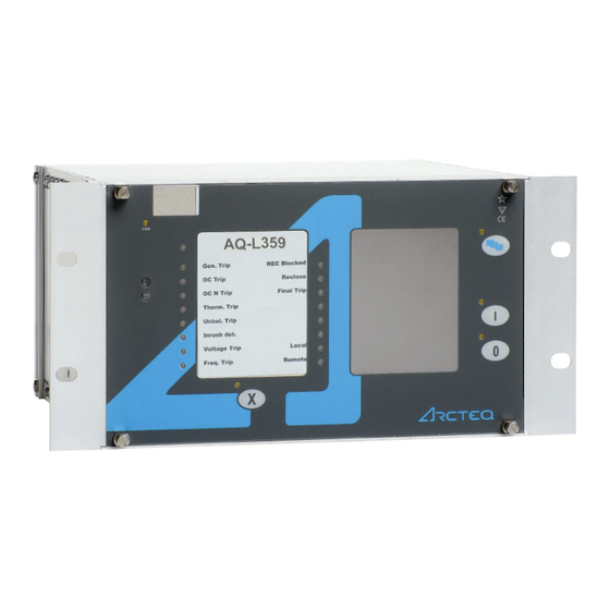
5 IED user interface A A Q Q -L3x9 -L3x9 5.1 Front panel Instruction manual Version: 2.00 5 IED user interface 5.1 Front panel The figure below presents the front panel structure for AQ-300 series units, while the table below the image describes the functions of the front panel's various elements. -
Page 12: Led Assignment
A A Q Q -L3x9 -L3x9 5 IED user interface Instruction manual 5.2 LED assignment Version: 2.00 Function Description The device has four (4) capacitive operational buttons: • "X" (below the LED label) latches and resets the LEDs. Operation • The button with a blue icon (top right) changes the touch screen menus. buttons •... - Page 13 5 IED user interface A A Q Q -L3x9 -L3x9 5.3 Touch screen Instruction manual Version: 2.00 The image below depicts the main screen of the front panel as well as the "ON", "OFF" and "Change screen" buttons. Figure. 5.3 - 2. The main menu and three operation buttons. The t The touch scr ouch screen...
- Page 14 A A Q Q -L3x9 -L3x9 5 IED user interface Instruction manual 5.3 Touch screen Version: 2.00 Figure. 5.3 - 3. Lock status indicator, as displayed in the main menu. The lock sta lock stat t us indic us indica a t t or or shows whether a password is required to unlock the device before parameters or settings can be changed.
- Page 15 5 IED user interface A A Q Q -L3x9 -L3x9 5.3 Touch screen Instruction manual Version: 2.00 Figure. 5.3 - 4. The password input screen. NOTICE! TICE! The lock icon is displayed even when the device has no password! Parameter menu In the parameters menu (below) you can view, set and edit certain parameters within the device.
- Page 16 A A Q Q -L3x9 -L3x9 5 IED user interface Instruction manual 5.3 Touch screen Version: 2.00 Figure. 5.3 - 5. The parameter set menu. The A A ctiv ctiva a t t e but e butt t on on activated the selected parameter set, which the device will now use. Depending on the device's configuration, the "Activate"...
- Page 17 5 IED user interface A A Q Q -L3x9 -L3x9 5.3 Touch screen Instruction manual Version: 2.00 • Floating-point number A number with a decimal point, entered with the number pad. Please note that the pad has the decimal point available only when the value can be entered as a floating-point number! •...
- Page 18 A A Q Q -L3x9 -L3x9 5 IED user interface Instruction manual 5.3 Touch screen Version: 2.00 Online measurement menu The online measurement menu displays real-time data depending on what is connected to the device. When you have selected a specific function block from the online functions list, clicking the V V ie iew w but butt t on takes you to a new window that displays the parameters and their current values.
- Page 19 5 IED user interface A A Q Q -L3x9 -L3x9 5.3 Touch screen Instruction manual Version: 2.00 Figure. 5.3 - 9. Event structure. NOTICE! TICE! The events menu does no not t display the whole event log, only the first few hundred items in the log! System settings menu Figure.
- Page 20 A A Q Q -L3x9 -L3x9 5 IED user interface Instruction manual 5.3 Touch screen Version: 2.00 Table. 5.3 - 5. The system settings. Setting Description System parameters and station bus settings Please contact your local network administrator for further information about these (IP address, settings.
-
Page 21: The Embedded Web Server
5 IED user interface A A Q Q -L3x9 -L3x9 5.4 The embedded web server Instruction manual Version: 2.00 Figure. 5.3 - 11. Turning on Q2. (1) First, we press Q2 on the touch screen to highlight the object. This causes Q2 to start blinking for a short while;... -
Page 22: Ethernet Connections
A A Q Q -L3x9 -L3x9 5 IED user interface Instruction manual 5.4 The embedded web server Version: 2.00 • provide remote or local firmware updgrades • perform administrative tasks. System requirements In order to access the device interface you need a compatible web browser as well as an Ethernet connection. - Page 23 5 IED user interface A A Q Q -L3x9 -L3x9 5.4 The embedded web server Instruction manual Version: 2.00 The diagram below depicts the three (3) different CPU versions and their structures: Figure. 5.4.1 - 12. The three CPU versions. Settings needed for Ethernet connection The AQ-300 devices can only be accessed over Ethernet-based communication protocols.
- Page 24 A A Q Q -L3x9 -L3x9 5 IED user interface Instruction manual 5.4 The embedded web server Version: 2.00 Make sure that your browser does NO NOT T use a proxy server while accessing an AQ-300 device. However, if there is a proxy server in your network, contact the system administrator and have them add an exception.
- Page 25 5 IED user interface A A Q Q -L3x9 -L3x9 5.4 The embedded web server Instruction manual Version: 2.00 Figure. 5.4.1 - 14. Using the RJ45 connection. The crossover cable's pinout has been depicted in the diagram below: Figure. 5.4.1 - 15. The pinout of the crossover cable. Please note that the cable's RJ45 connector can also be connected to an Ethernet switch.
-
Page 26: Getting Started
A A Q Q -L3x9 -L3x9 5 IED user interface Instruction manual 5.4 The embedded web server Version: 2.00 ST-type fiber optic connection The ST-type fiber optic connector of the 100Base-FX Ethernet provides a connection to an Ethernet switch with an identical fiber optic input. When using this connection, all the network's IEDs with client functionalities (e.g. - Page 27 5 IED user interface A A Q Q -L3x9 -L3x9 5.4 The embedded web server Instruction manual Version: 2.00 Figure. 5.4.2 - 17. Web server elements. The menu that is currently selected is highlighted in black (in the image above, the main menu is selected).
-
Page 28: Menu Items
A A Q Q -L3x9 -L3x9 5 IED user interface Instruction manual 5.4 The embedded web server Version: 2.00 5.4.3 Menu items Main menu Figure. 5.4.3 - 18. The main menu and its elements. In the main menu you can control the device's front panel. The image of a touch screen (located on the right) behaves the same way as the actual touch screen. - Page 29 5 IED user interface A A Q Q -L3x9 -L3x9 5.4 The embedded web server Instruction manual Version: 2.00 Parameters menu Figure. 5.4.3 - 19. The parameters menu and its elements. You can view and change various parameters and variables in this menu. You can manage the different parameter sets by resetting, renaming, exporting and importing them.
- Page 30 A A Q Q -L3x9 -L3x9 5 IED user interface Instruction manual 5.4 The embedded web server Version: 2.00 In the "Parameter set" section of the page there are options for managing the parameter sets. The section lists all the available parameter sets, and each can be manipulated with the buttons located on the right of the line.
- Page 31 5 IED user interface A A Q Q -L3x9 -L3x9 5.4 The embedded web server Instruction manual Version: 2.00 Figure. 5.4.3 - 21. The system settings menu. Table. 5.4.3 - 7. The system setting sections and their content. Section name Description If enabled, the device asks you to confirm the saving of new settings by pressing the "I"...
- Page 32 A A Q Q -L3x9 -L3x9 5 IED user interface Instruction manual 5.4 The embedded web server Version: 2.00 Section name Description Contain the parameters to control the LCD panel's behaviour. The light switches off after its set timeout. LCD backlight The "Backlight group"...
- Page 33 5 IED user interface A A Q Q -L3x9 -L3x9 5.4 The embedded web server Instruction manual Version: 2.00 Figure. 5.4.3 - 23. Elements of the events menu. With the R R e e fr fresh esh button you can refresh the list displaying the events, the E E ra rase all e se all ev v ents ents button clears the list on the screen, and the Expor...
- Page 34 A A Q Q -L3x9 -L3x9 5 IED user interface Instruction manual 5.4 The embedded web server Version: 2.00 Figure. 5.4.3 - 25. Disturbance recorder. The "Recorded disturbances" section lists all disturbance records. You can refresh the list with the R R e e fr fresh esh button to display any new disturbance records that have occurred after the page was opened or refreshed last.
- Page 35 5 IED user interface A A Q Q -L3x9 -L3x9 5.4 The embedded web server Instruction manual Version: 2.00 You can set a setpoint by clicking anywhere on the graph, and the positioning the cursor to a desired second point. The preview then displays the timestamp of the first setpoint, and the time difference between the two setpoints.
- Page 36 A A Q Q -L3x9 -L3x9 5 IED user interface Instruction manual 5.4 The embedded web server Version: 2.00 Advanced Figure. 5.4.3 - 29. The Advanced menu. This menu displays the additional, more advanced options. You can set a password request before a user is allowed access to these options.
- Page 37 5 IED user interface A A Q Q -L3x9 -L3x9 5.4 The embedded web server Instruction manual Version: 2.00 The Ge Get r t repor eport t button generates a .zip file that has all of the log files archived together. The files have valuable information and they can help in analyzing errors and malfunctions;...
-
Page 38: Troubleshooting
A A Q Q -L3x9 -L3x9 5 IED user interface Instruction manual 5.4 The embedded web server Version: 2.00 Figure. 5.4.3 - 32. Update manager. 5.4.4 Troubleshooting Some browsers have a tendency to handle and cache various JavaScript function improperly, and this may cause anomalies and errors in the interface. -
Page 39: Soft E Set T Up Up
6 Software setup A A Q Q -L3x9 -L3x9 6.1 Functions included in AQ-L3x9 Instruction manual Version: 2.00 6 Software setup 6.1 Functions included in AQ-L3x9 In this chapter are presented the protection and control functions as well as the monitoring functions. The implemented protection functions are listed in the table below. - Page 40 A A Q Q -L3x9 -L3x9 6 Software setup Instruction manual 6.2 Measurements Version: 2.00 Figure. 6.2.1 - 33. Example connection. Table. 6.2.1 - 9. Values for the example above. Phase current CT: Ring core CT in Input I0: CT primary 100A I0CT primary 10A CT secondary 5A I0CT secondary 1A...
- Page 41 6 Software setup A A Q Q -L3x9 -L3x9 6.2 Measurements Instruction manual Version: 2.00 The performed basic calculation results the Fourier basic harmonic magnitude and angle and the true RMS value. These results are processed by subsequent protection function blocks and they are available for on-line displaying as well.
-
Page 42: Voltage Measurement And Scaling
A A Q Q -L3x9 -L3x9 6 Software setup Instruction manual 6.2 Measurements Version: 2.00 Measured value Dim. Explanation Angle Ch - I3 degree Vector position of the current in channel IL3 Current Ch - I4 A(secondary) Fourier basic component of the current in channel I4 Angle Ch - I4 degree Vector position of the current in channel I4... - Page 43 6 Software setup A A Q Q -L3x9 -L3x9 6.2 Measurements Instruction manual Version: 2.00 The connection of the first three VT secondary windings must be set to reflect actual physical connection of the main VTs. The associated parameter is “Connection U1-3“. The selection can be: Ph-N, Ph-Ph or Ph-N-Isolated.
- Page 44 A A Q Q -L3x9 -L3x9 6 Software setup Instruction manual 6.2 Measurements Version: 2.00 Figure. 6.2.2 - 36. Phase-to-phase connection. Ph-N Voltage: Residual voltage: Rated Primary U1-3: 20kV Rated Primary U4: 11.54A (=20kV/√3) Range: Type 100 The fourth input is reserved for zero sequence voltage or for a voltage from the other side of the circuit breaker for synchron switching.
- Page 45 6 Software setup A A Q Q -L3x9 -L3x9 6.2 Measurements Instruction manual Version: 2.00 Parameter name Title Selection range Default VT4_Ch13Nom_EPar_ Connection U1-3 Ph-N, Ph-Ph, Ph-N-Isolated Ph-N Selection of the fourth channel input: phase-to-neutral or phase-to-phase voltage VT4_Ch4Nom_EPar_ Connection U4 Ph-N,Ph-Ph Ph-Ph Definition of the positive direction of the first three input channels, given as normal or inverted...
-
Page 46: Line Measurement
A A Q Q -L3x9 -L3x9 6 Software setup Instruction manual 6.2 Measurements Version: 2.00 Measured value Dim. Explanation Angle Ch - U2 degree Vector position of the voltage in channel UL2 Voltage Ch - U3 V(secondary) Fourier basic component of the voltage in channel UL3 Angle Ch - U3 degree Vector position of the voltage in channel UL3... - Page 47 6 Software setup A A Q Q -L3x9 -L3x9 6.2 Measurements Instruction manual Version: 2.00 The outputs of the line measurement function are • displayed measured values • reports to the SCADA system. NOTICE! TICE! The scaling values are entered as parameter setting for the “Voltage transformer input” function block and for the “Current transformer input”...
- Page 48 A A Q Q -L3x9 -L3x9 6 Software setup Instruction manual 6.2 Measurements Version: 2.00 Figure. 6.2.3 - 37. Measured values in a configuration for compensated networks. The available quantities are described in the configuration description documents. Reporting the measured values and the changes For reporting, additional information is needed, which is defined in parameter setting.
- Page 49 6 Software setup A A Q Q -L3x9 -L3x9 6.2 Measurements Instruction manual Version: 2.00 The selection of the reporting mode items is explained in next chapters. "Amplitude" mode of reporting If the “Amplitude” mode is selected for reporting, a report is generated if the measured value leaves the deadband around the previously reported value.
- Page 50 A A Q Q -L3x9 -L3x9 6 Software setup Instruction manual 6.2 Measurements Version: 2.00 Parameter name Title Dim. Step Default Range value for the apparent power MXU_SRange_FPar_ Range value - S 100000 0.01 Deadband value for the current MXU_IDeadB_FPar_ Deadband value - I 2000 Range value for the current...
- Page 51 6 Software setup A A Q Q -L3x9 -L3x9 6.2 Measurements Instruction manual Version: 2.00 Figure. 6.2.3 - 39. Reporting when Integrated mode is selected. Periodic reporting Periodic reporting is generated independently of the changes of the measured values when the defined time period elapses.
-
Page 52: Protection Functions
A A Q Q -L3x9 -L3x9 6 Software setup Instruction manual 6.3 Protection functions Version: 2.00 Parameter name Title Dim. Step Default Deadband value for the phase-to-neutral voltage MXU_UPhDeadB_FPar_ Deadband value - U ph-N 0.01 Range value for the phase-to-neutral voltage MXU_UPhRange_FPar_ Range value - U ph-N 1000... - Page 53 6 Software setup A A Q Q -L3x9 -L3x9 6.3 Protection functions Instruction manual Version: 2.00 The variables in the image above are: • t (seconds) = theoretical operating time if G>G (without additional time delay) • G = measured peak value or Fourier base harmonic of the phase currents •...
-
Page 54: Residual Instantaneous Overcurrent Protection (I0>; 50N/51N)
A A Q Q -L3x9 -L3x9 6 Software setup Instruction manual 6.3 Protection functions Version: 2.00 6.3.2 Residual instantaneous overcurrent protection (I0>; 50N/51N) The residual instantaneous overcurrent protection function operates according to instantaneous characteristics, using the residual current (IN=3Io). The setting value is a parameter, and it can be doubled with dedicated input binary signal. -
Page 55: Three-Phase Time Overcurrent Protection (I>; 50/51)
6 Software setup A A Q Q -L3x9 -L3x9 6.3 Protection functions Instruction manual Version: 2.00 The algorithm generates a trip command without additional time delay based on the Fourier components of the phase currents or peak values of the phase currents in case if the user set pick-up value is exceeded. - Page 56 A A Q Q -L3x9 -L3x9 6 Software setup Instruction manual 6.3 Protection functions Version: 2.00 The function includes a blocking signal input which can be configured by user from either IED internal binary signals or IED binary inputs through the programmable logic. Operating characteristics of the definite time is presented in the figure below.
- Page 57 6 Software setup A A Q Q -L3x9 -L3x9 6.3 Protection functions Instruction manual Version: 2.00 Table. 6.3.3 - 24. Parameters and operating curve types for the IDMT characteristics. Curve family Characteristics α NI (normally inverse) 0.14 0.02 VI (very inverse) 13.5 EI (extremely inverse) LTI (long time inverse)
- Page 58 A A Q Q -L3x9 -L3x9 6 Software setup Instruction manual 6.3 Protection functions Version: 2.00 Figure. 6.3.3 - 47. IEC - VI operating curves with minimum and maximum pick-up settings and TMS settings from 0.05 to 20. Figure. 6.3.3 - 48. IEC - EI operating curves with minimum and maximum pick-up settings and TMS settings from 0.05 to 20.
- Page 59 6 Software setup A A Q Q -L3x9 -L3x9 6.3 Protection functions Instruction manual Version: 2.00 Figure. 6.3.3 - 49. IEC - LTI operating curves with minimum and maximum pick-up settings and TMS settings from 0.05 to 20. Figure. 6.3.3 - 50. IEEE/ANSI - NI operating curves with minimum and maximum pick-up settings and TMS settings from 0.05 to 20.
- Page 60 A A Q Q -L3x9 -L3x9 6 Software setup Instruction manual 6.3 Protection functions Version: 2.00 Figure. 6.3.3 - 51. IEEE/ANSI - MI operating curves with minimum and maximum pick-up settings and TMS settings from 0.05 to 20. Figure. 6.3.3 - 52. IEEE/ANSI - VI operating curves with minimum and maximum pick-up settings and TMS settings from 0.05 to 20.
- Page 61 6 Software setup A A Q Q -L3x9 -L3x9 6.3 Protection functions Instruction manual Version: 2.00 Figure. 6.3.3 - 53. IEEE/ANSI - EI operating curves with minimum and maximum pick-up settings and TMS settings from 0.05 to 20. Figure. 6.3.3 - 54. IEEE/ANSI - LTI operating curves with minimum and maximum pick-up settings and TMS settings from 0.05 to 20.
- Page 62 A A Q Q -L3x9 -L3x9 6 Software setup Instruction manual 6.3 Protection functions Version: 2.00 Figure. 6.3.3 - 55. IEEE/ANSI - LTVI operating curves with minimum and maximum pick-up settings and TMS settings from 0.05 to 20. Figure. 6.3.3 - 56. IEEE/ANSI - LTEI operating curves with minimum and maximum pick-up settings and TMS settings from 0.05 to 20.
- Page 63 6 Software setup A A Q Q -L3x9 -L3x9 6.3 Protection functions Instruction manual Version: 2.00 Resetting characteristics for the function depends on the selected operating time characteristics. For the IEC type IDMT characteristics the reset time is user settable and for the ANSI/IEEE type characteristics the resetting time follows equation below.
-
Page 64: Residual Time Overcurrent Protection (I0>; 50N/51N)
A A Q Q -L3x9 -L3x9 6 Software setup Instruction manual 6.3 Protection functions Version: 2.00 Table. 6.3.3 - 26. Setting parameters of the time overcurrent function. Setting Parameter value Step Default Description / range DefinitTime IEC Inv IEC VeryInv IEC ExtInv IEC LongInv ANSI Inv... - Page 65 6 Software setup A A Q Q -L3x9 -L3x9 6.3 Protection functions Instruction manual Version: 2.00 The variables in the image above are: • t (seconds) = theoretical operating time if G>G (without additional time delay) • G = measured value of the Fourier base harmonic of the residual current •...
-
Page 66: Three-Phase Directional Overcurrent Protection (Idir>; 67)
A A Q Q -L3x9 -L3x9 6 Software setup Instruction manual 6.3 Protection functions Version: 2.00 Table. 6.3.4 - 27. Setting parameters of the residual time overcurrent function. Setting Parameter value / Step Default Description Range DefinitTime IEC Inv IEC VeryInv IEC ExtInv IEC LongInv ANSI Inv... - Page 67 6 Software setup A A Q Q -L3x9 -L3x9 6.3 Protection functions Instruction manual Version: 2.00 Figure. 6.3.5 - 59. The structure of the directional overcurrent protection algorithm. Based on the measured voltages and currents the function block selects the lowest calculated loop impedance of the six loops (L1L2, L2L3, L3L1, L1N, L2N, L3N).
- Page 68 A A Q Q -L3x9 -L3x9 6 Software setup Instruction manual 6.3 Protection functions Version: 2.00 Figure. 6.3.5 - 60. Directional decision characteristics. The voltage must be above 5% of the rated voltage and the current must also be measurable. If the voltages are below 5% of the rated voltage then the algorithm substitutes the small values with the voltage values stored in the memory.
-
Page 69: Residual Directional Overcurrent Protection (I0Dir>; 67N)
6 Software setup A A Q Q -L3x9 -L3x9 6.3 Protection functions Instruction manual Version: 2.00 Setting value Parameter Step Default Description / range DefinitTime IEC Inv IEC VeryInv IEC ExtInv IEC LongInv ANSI Inv Operating mode selection of the function. Can be disabled, Operation ANSI ModInv DefinitTime... - Page 70 A A Q Q -L3x9 -L3x9 6 Software setup Instruction manual 6.3 Protection functions Version: 2.00 Figure. 6.3.6 - 61. The structure of the residual directional overcurrent protection algorithm. The block of the directional decision generates a signal of TRUE value if the UN=3Uo zero sequence voltage and the IN=-3Io current is sufficient for directional decision, and the angle difference between the vectors is within the preset range.
- Page 71 6 Software setup A A Q Q -L3x9 -L3x9 6.3 Protection functions Instruction manual Version: 2.00 Figure. 6.3.6 - 63. Wattmetric and varmetric operating characteristics. In the in the figure above are presented the characteristics of the wattmetric and varmetric operating principles in forward direction.
-
Page 72: Current Unbalance Protection (60)
A A Q Q -L3x9 -L3x9 6 Software setup Instruction manual 6.3 Protection functions Version: 2.00 Setting Parameter value / Step Default Description range DefinitTime IEC Inv IEC VeryInv IEC ExtInv IEC LongInv ANSI Inv ANSI Selection of the function disabled and the timing ModInv Operation DefinitTime... - Page 73 6 Software setup A A Q Q -L3x9 -L3x9 6.3 Protection functions Instruction manual Version: 2.00 Figure. 6.3.7 - 64. The structure of the current unbalance protection algorithm. The analogue signal processing principal scheme is presented in the figure below. Figure.
-
Page 74: Circuit Breaker Failure Protection (Cbfp; 50Bf/52Bf)
A A Q Q -L3x9 -L3x9 6 Software setup Instruction manual 6.3 Protection functions Version: 2.00 Table. 6.3.7 - 30. Setting parameters of the current unbalance function. Setting Parameter value / Step Default Description range Operation Selection for the function enabled or disabled. Start Activated Selection if the function issues either "Start"... - Page 75 6 Software setup A A Q Q -L3x9 -L3x9 6.3 Protection functions Instruction manual Version: 2.00 Figure. 6.3.8 - 66. Operation logic of the CBFP function. Table. 6.3.8 - 31. Setting parameters of the CBFP function. Setting Parameter value / Step Default Description range...
-
Page 76: Overvoltage Protection (U>; 59)
A A Q Q -L3x9 -L3x9 6 Software setup Instruction manual 6.3 Protection functions Version: 2.00 6.3.9 Overvoltage protection (U>; 59) The overvoltage protection function measures three phase to ground voltages. If any of the measured voltages is above the pick-up setting, a start signal is generated for the phases individually. Figure. -
Page 77: Residual Overvoltage Protection (U0>; 59N)
6 Software setup A A Q Q -L3x9 -L3x9 6.3 Protection functions Instruction manual Version: 2.00 Figure. 6.3.10 - 68. The principal structure of the undervoltage function. The general start signal is set active if the voltage of any of the three measured voltages is below the level defined by pick-up setting value. -
Page 78: Thermal Overload Protection (T>; 49)
A A Q Q -L3x9 -L3x9 6 Software setup Instruction manual 6.3 Protection functions Version: 2.00 Figure. 6.3.11 - 69. The principal structure of the residual overvoltage function. The general start signal is set active if the measured residual voltage is above the level defined by pick- up setting value. - Page 79 6 Software setup A A Q Q -L3x9 -L3x9 6.3 Protection functions Instruction manual Version: 2.00 Figure. 6.3.12 - 70. The principal structure of the thermal overload function. In the figure above is presented the principal structure of the thermal overload function. Theinputs of the function are the maximum of TRMS values of the phase currents, ambienttemperature setting, binary input status signals and setting parameters.
-
Page 80: Line Differential Protection (87L) - Transformer Not In Protected Zone
A A Q Q -L3x9 -L3x9 6 Software setup Instruction manual 6.3 Protection functions Version: 2.00 Setting Parameter value / Step Default Description range Rated 60…200 Rated temperature of the protected object. temperature Base Rated ambient temperature of the device related to allowed 0…40 deg 40 deg temperature... - Page 81 6 Software setup A A Q Q -L3x9 -L3x9 6.3 Protection functions Instruction manual Version: 2.00 Figure. 6.3.13 - 71. Structure of the line differential protection algorithm. The inputs are • the Fourier base component values of three phase currents at the local line end •...
- Page 82 A A Q Q -L3x9 -L3x9 6 Software setup Instruction manual 6.3 Protection functions Version: 2.00 Table. 6.3.13 - 36. Current compensation parameters. Parameter Setting range Step Default Explanation LocalRatio 0.10…2.00 0.01 1.00 Local end current ratio compensation factor. RemoteRatio 0.10…2.00 0.01 1.00...
- Page 83 6 Software setup A A Q Q -L3x9 -L3x9 6.3 Protection functions Instruction manual Version: 2.00 Figure. 6.3.13 - 72. The line differential protection characteristics. Decision logic Decision logic The decision logic combines the following binary signals: • Start signals of the line differential characteristic module •...
- Page 84 A A Q Q -L3x9 -L3x9 6 Software setup Instruction manual 6.3 Protection functions Version: 2.00 Table. 6.3.13 - 38. Measured and displayed values of line differential function. Measured value Dim. Explanation I Diff L1 p.u. Differential current in line L1 I Diff L2 p.u.
- Page 85 6 Software setup A A Q Q -L3x9 -L3x9 6.3 Protection functions Instruction manual Version: 2.00 Table. 6.3.13 - 40. The binary output signals of the line differential function. Binary output signal Signal title Explanation Trip command of the line differential protection function DIFF87L_T _TrL1_ rL1_GrI_ Trip L1...
-
Page 86: Line Differential Protection (87L) - Transformer In Protected Zone
A A Q Q -L3x9 -L3x9 6 Software setup Instruction manual 6.3 Protection functions Version: 2.00 Figure. 6.3.13 - 74. Process bus settings for line differential protection. 6.3.14 Line differential protection (87L) – transformer in protected zone The AQ 300 series has two kinds of line differential algorithms available, one with transformer in the protected zone and one without. - Page 87 6 Software setup A A Q Q -L3x9 -L3x9 6.3 Protection functions Instruction manual Version: 2.00 • the harmonic restraint decision from the remote end • the sampled values of three local phase currents • parameters • status signals. The outputs are •...
- Page 88 A A Q Q -L3x9 -L3x9 6 Software setup Instruction manual 6.3 Protection functions Version: 2.00 • Decision logic The decision logic module decides if the differential current of the individual phases is above the characteristic curve of the differential protection function. The second and fifth harmonic ratio of the local current, relative to the basic harmonic content can restrain the operation of the differential protection function.
- Page 89 6 Software setup A A Q Q -L3x9 -L3x9 6.3 Protection functions Instruction manual Version: 2.00 Table. 6.3.14 - 42. Vector shift compensation with transformation to the delta delta side. conn. Code Transformation of the local side currents Transformation of the remote side currents group Dy11 Dz10...
- Page 90 A A Q Q -L3x9 -L3x9 6 Software setup Instruction manual 6.3 Protection functions Version: 2.00 conn. Code Transformation of the local side currents Transformation of the remote side currents group Yd11 Yz11 Magnit gnitude compensa ude compensation tion The differential currents are calculated using the (I1Rshift, I1Sshift, I1Tshift) and (I2Rshift, I2Sshift, I2Tshift) values and the DIF87L_TRPr_IPar (TR local) and DIF87L_TRSec_IPar (TR remote) parameters, defined by the turn’s ratio of the transformer and that of the current transformers, resulting the currents with the apostrophe (’).
- Page 91 6 Software setup A A Q Q -L3x9 -L3x9 6.3 Protection functions Instruction manual Version: 2.00 Figure. 6.3.14 - 76. Principal scheme of the vector shift compensation. The inputs are: • The three phase Fourier current vectors of the local side (IL1_F1_local,IL2_F1_local, IL3_F1_local) •...
- Page 92 A A Q Q -L3x9 -L3x9 6 Software setup Instruction manual 6.3 Protection functions Version: 2.00 The differential current can be high in case of over-excitation of the transformer, due to thecurrent distortion caused by the transformer iron core symmetric saturation. In this case thefifth harmonic content of the differential current is applied to disable the operation of thedifferential protection function.
- Page 93 6 Software setup A A Q Q -L3x9 -L3x9 6.3 Protection functions Instruction manual Version: 2.00 Parameters The outputs of the modules are the status signals for each phase and for second and fifth harmonics separately, indicating the restraint status caused by high harmonic contents. Figure.
- Page 94 A A Q Q -L3x9 -L3x9 6 Software setup Instruction manual 6.3 Protection functions Version: 2.00 Figure. 6.3.14 - 79. Principal scheme of the current magnitude calculation. The inputs are the Fourier vectors of the phase-shifted currents: The differential currents after phase-shift: The local currents after phase-shift: The remote currents after phase-shift: The outputs are the magnitude of the calculated currents:...
- Page 95 6 Software setup A A Q Q -L3x9 -L3x9 6.3 Protection functions Instruction manual Version: 2.00 The magnitudes of the remote currents after phase-shift: The restraint (bias) current for all phases is calculated as the maximum of the six currents: M_Ibias = MAX(M_I1Rshift';...
- Page 96 A A Q Q -L3x9 -L3x9 6 Software setup Instruction manual 6.3 Protection functions Version: 2.00 Figure. 6.3.14 - 81. Principal scheme of evaluation of differential protection characteristics. The inputs are the magnitude of the calculated currents: The magnitudes of the differential currents after phase-shift: The magnitudes of the local currents after phase-shift: The magnitudes of the remote currents after phase-shift: Decision logic...
- Page 97 6 Software setup A A Q Q -L3x9 -L3x9 6.3 Protection functions Instruction manual Version: 2.00 The inputs are the internal calculated status signals of the differential characteristics module, those of the 2nd harmonic restraint and 5th harmonic restraint modules and binary input parameters. These signals are processed by the decision logic of the device described in the following figure.
- Page 98 A A Q Q -L3x9 -L3x9 6 Software setup Instruction manual 6.3 Protection functions Version: 2.00 I2n = 1.05 A (secondary side) Example se Example set t ting parame ting paramet t ers Substation “A”, 120 kV TR local = 91 % (This is a free choice, giving the currents of the 120 kV side current transformer’s current, related to the rated current of the CT.) TR remote = 105 %...
- Page 99 6 Software setup A A Q Q -L3x9 -L3x9 6.3 Protection functions Instruction manual Version: 2.00 Figure. 6.3.14 - 83. Function block of the line differential protection function with transformer within protected zone. The binary input and output status signals of the line differential function with transformerwithin protected zone are listed in tables below.
- Page 100 A A Q Q -L3x9 -L3x9 6 Software setup Instruction manual 6.3 Protection functions Version: 2.00 Binary output signal Signal title Explanation DIFF87L_R _Rec12_ ec12_GrI_ Received Ch12 Free configurable signal received via communication channel Communication failure signal DIFF87L_CommF _CommFail_ ail_GrI_ CommFail Signal indicating communication failure Setting considerations of the line differential protection...
- Page 101 6 Software setup A A Q Q -L3x9 -L3x9 6.3 Protection functions Instruction manual Version: 2.00 This indicates that the connection group of this transformer is Yd11.) Here the primary currents form a symmetrical system: The secondary currents can be seen on the figure (please consider the division factor √3 in the effective turn’s ratio): P P ha hase se-t -to-pha o-phase fa...
- Page 102 A A Q Q -L3x9 -L3x9 6 Software setup Instruction manual 6.3 Protection functions Version: 2.00 The delta side currents can be seen on this figure: P P ha hase se-t -to-pha o-phase fa se fault on the delta ult on the delta side side Assume I current on the secondary delta side between phases "s"...
- Page 103 6 Software setup A A Q Q -L3x9 -L3x9 6.3 Protection functions Instruction manual Version: 2.00 Figure. 6.3.14 - 88. Currents inside the transformer at single phase fault at the Y side (Bauch effect). On this figure k is the current ratio. The primary Y side currents are: On the delta side there are no currents flowing out of the transformer: Assume I fault current at the Y side in phase R in case of solidly grounded neutral.
- Page 104 A A Q Q -L3x9 -L3x9 6 Software setup Instruction manual 6.3 Protection functions Version: 2.00 Figure. 6.3.14 - 89. Currents inside the transformer at single phase fault at the Y side, supply at the delta side. On this figure k is the current ratio. The primary Y side currents are: The delta side currents can be seen on this figure: C C heck...
- Page 105 6 Software setup A A Q Q -L3x9 -L3x9 6.3 Protection functions Instruction manual Version: 2.00 The secondary currents are drawn in the above-mentioned figure (consider the division by √3 as defined by the turn's ratio): The secondary currents are transformed by the unit matrix. It means that only the turn's ratio is considered: These currents are the same (with the round-off errors of.
- Page 106 A A Q Q -L3x9 -L3x9 6 Software setup Instruction manual 6.3 Protection functions Version: 2.00 The input currents from the secondary side of the transformer can be seen in the above-mentioned figure: These secondary side currents are transformed with the unit matrix, so only the turn's ratio has to be considered: These currents are the same (with the round-off errors of.
- Page 107 6 Software setup A A Q Q -L3x9 -L3x9 6.3 Protection functions Instruction manual Version: 2.00 The input currents from the primary Y side can be seen in the above-mentioned figure: The transformation of these Y side currents: These currents are the same (with the round-off errors of. 0.5%) as the secondary transformed currents, but multiplied by „-1”.
- Page 108 A A Q Q -L3x9 -L3x9 6 Software setup Instruction manual 6.3 Protection functions Version: 2.00 These secondary currents are transformed with the unit matrix, so only the turn’s ratio is considered: Because of zero currents, the differential protection is stable. Now suppose I fault current in phase R on the external primary side of the transformer, if the neutral is grounded.
-
Page 109: Overfrequency Protection (F>; 81O)
6 Software setup A A Q Q -L3x9 -L3x9 6.3 Protection functions Instruction manual Version: 2.00 The currents are balanced; the differential protection does not generate a trip command. Setting parameters Table. 6.3.14 - 45. Setting parameters of the line differential protection with transformer within protected zone. Parameter Setting range Step Default... -
Page 110: Underfrequency Protection (F<; 81U)
A A Q Q -L3x9 -L3x9 6 Software setup Instruction manual 6.3 Protection functions Version: 2.00 The over-frequency protection function is usually applied to decrease generation to control the system frequency. Another possible application is the detection of unintended island operation of distributed generation and some consumers. -
Page 111: Rate-Of-Change Of Frequency Protection (Fd/Ft>/<; 81R)
6 Software setup A A Q Q -L3x9 -L3x9 6.3 Protection functions Instruction manual Version: 2.00 For the confirmation of the measured frequency, at least four subsequent identical measurements are needed. Similarly, four invalid measurements are needed to reset the measured frequency to zero. The basic criterion is that the evaluated voltage should be above 30% of the rated voltage value. -
Page 112: Pole Slip (78)
A A Q Q -L3x9 -L3x9 6 Software setup Instruction manual 6.3 Protection functions Version: 2.00 Setting Parameter value / Step Default Description range Start Activated Selection if the function issues either “Start” signal alone orboth Deactivated signal only Deactivated “Start”... - Page 113 6 Software setup A A Q Q -L3x9 -L3x9 6.3 Protection functions Instruction manual Version: 2.00 The characteristic feature of pole slipping is that the impedance locus leaves the characteristic at a location, where the sign of the calculated resistance (e.g –Rleaving) is opposite to that of the entering location (e.g.
- Page 114 A A Q Q -L3x9 -L3x9 6 Software setup Instruction manual 6.3 Protection functions Version: 2.00 • the binary output status signals. The software modules of the pole slipping protection function are as follows: Z_CAL Z_CALC C calculates the impedances (R+jX) of the three phase-phase measuring current loops. Quadrila Quadrilat t eral charact eral characteristic...
- Page 115 6 Software setup A A Q Q -L3x9 -L3x9 6.3 Protection functions Instruction manual Version: 2.00 = the positive sequence resistance of the line or cable section between the fault location and the relay location = the positive sequence inductance of the line or cable section between the fault location and the relay location L1, L2, L3 = the three phases The applied numerical method is solving the differential equation of the faulty loop, based on the...
- Page 116 A A Q Q -L3x9 -L3x9 6 Software setup Instruction manual 6.3 Protection functions Version: 2.00 The characteristics of the pole slip protection function (Quadrilateral characteristics) The method is an impedance-based comparison. The operate decision is based on quadrilateral characteristics. The calculated R1 and X1= L1 co-ordinate values of the three measuring loops define three points on the complex impedance plane.
- Page 117 6 Software setup A A Q Q -L3x9 -L3x9 6.3 Protection functions Instruction manual Version: 2.00 The input values are calculated by the module Z_CALC. Table. 6.3.18 - 51. The input calculated impedances of the quadrilateral characteristics module. Calculated value Dim.
- Page 118 A A Q Q -L3x9 -L3x9 6 Software setup Instruction manual 6.3 Protection functions Version: 2.00 The duration of the trip pulse is defined by parameter setting Table. 6.3.18 - 55. Trip pulse parameter setting. Parameter Setting value / range Description Operation Parameter for disabling the function.
-
Page 119: Teleprotection (85)
6 Software setup A A Q Q -L3x9 -L3x9 6.3 Protection functions Instruction manual Version: 2.00 Table. 6.3.18 - 58. Minimal current enabling. Parameter Setting value / range Step Description IPh Base Sens 10…30 Definition of minimal current enabling impedance calculation The positive sequence current is considered to be sufficient if it is above the level set by parameter PSLIP78_Imin_IPar_ (IPh Base Sens). - Page 120 A A Q Q -L3x9 -L3x9 6 Software setup Instruction manual 6.3 Protection functions Version: 2.00 • Direct trip command • Permissive signal • Blocking signal. To increase the reliability of operation, in this implementation of the telecommunication function the sending end generates a signal, which can be transmitted via two different channels.
- Page 121 6 Software setup A A Q Q -L3x9 -L3x9 6.3 Protection functions Instruction manual Version: 2.00 Figure. 6.3.19 - 96. Permissive Underreach Transfer Trip with Pickup: Send signal generation. Figure. 6.3.19 - 97. Permissive Underreach Transfer Trip with Pickup: Trip command generation. Permissive Underreach Transfer Trip with Overreach The protection system uses telecommunication, with underreach setting at each section end.
- Page 122 A A Q Q -L3x9 -L3x9 6 Software setup Instruction manual 6.3 Protection functions Version: 2.00 Figure. 6.3.19 - 99. Permissive Underreach Transfer Trip with Overreach: Trip command generation. P P ermissiv ermissive Ov e Overr erreach T each Transf ransfer T er Trip (PO rip (POT T T T ) )
- Page 123 6 Software setup A A Q Q -L3x9 -L3x9 6.3 Protection functions Instruction manual Version: 2.00 The protection system uses telecommunication. The signal is transmitted when a fault is detected in forward direction. This signal is prolonged if a general trip command is generated. Receipt of the signal at the other end permits the initiation of tripping by the local protection if it detected a fault in forward direction.
- Page 124 A A Q Q -L3x9 -L3x9 6 Software setup Instruction manual 6.3 Protection functions Version: 2.00 Figure. 6.3.19 - 104. Directional blocking: Send signal generation. Figure. 6.3.19 - 105. Directional blocking: Trip command generation. D D ir irect underr ect underreaching transf eaching transfer trip (DUT er trip (DUTT T ) ) The IEC standard name of this mode of operation is Intertripping Underreach Protection (IUP).
- Page 125 6 Software setup A A Q Q -L3x9 -L3x9 6.3 Protection functions Instruction manual Version: 2.00 Figure. 6.3.19 - 106. Directional Underreaching Transfer Trip: Send signal generation. Figure. 6.3.19 - 107. Directional Underreaching Transfer Trip: Trip command generation. Function block Figure.
-
Page 126: Inrush Current Detection (68)
A A Q Q -L3x9 -L3x9 6 Software setup Instruction manual 6.3 Protection functions Version: 2.00 Signal title Explanation Receive opp. 2 Signal2 received from the opposite end Z Gen.start Fw Protection start in forward direction Z Underreach Start Start of the underreaching zone (e.g. Z1) Z Overreach Start Start of the overreaching zone (e.g. -
Page 127: Stub Protection
6 Software setup A A Q Q -L3x9 -L3x9 6.3 Protection functions Instruction manual Version: 2.00 The inrush current detection function block analyses the second harmonic content of the current, related to the fundamental harmonic. If the content is high, then the assigned status signal is set to “true”... - Page 128 A A Q Q -L3x9 -L3x9 6 Software setup Instruction manual 6.3 Protection functions Version: 2.00 • Binary inputs for enabling and activating the operation • Parameters. The output of the stub protection function is • A binary output trip command to be directed to the appropriate circuit breaker(s). If any of the phase currents is above the start current and the binary status signal activates the operation, then after a user-defined time delay the function generates a trip command.
-
Page 129: Distance Protection
6 Software setup A A Q Q -L3x9 -L3x9 6.3 Protection functions Instruction manual Version: 2.00 Signal Binary input signal Explanation title The programmed True state of this signal indicates the open state of the STB50_A _Activ ctiva a t t e_ e_GrO_ Activate circuit breaker or maybe the isolator. - Page 130 A A Q Q -L3x9 -L3x9 6 Software setup Instruction manual 6.3 Protection functions Version: 2.00 Figure. 6.3.22 - 110. Structure of the distance protection. The inputs are: • Sampled values and Fourier components of three phase voltages • Sampled values and Fourier components of three phase currents •...
- Page 131 6 Software setup A A Q Q -L3x9 -L3x9 6.3 Protection functions Instruction manual Version: 2.00 Principle of the impedance calculation The distance protection continuously measures the impedances in the six possible fault loops. The calculation is performed in the phase-to-phase loops based on the line-to-line voltages and the difference of the affected phase currents, while in the phase-to-earth loops the phase voltage is divided by the phase current compounded with the zero sequence current.
- Page 132 A A Q Q -L3x9 -L3x9 6 Software setup Instruction manual 6.3 Protection functions Version: 2.00 It can be proven that if the setting value of the complex earth fault compensation factor is correct, the appropriate application of the formulas in the table will always yield the positive sequence impedance between the fault location and the relay location.
- Page 133 6 Software setup A A Q Q -L3x9 -L3x9 6.3 Protection functions Instruction manual Version: 2.00 = the positive sequence resistance of the line or cable section between the fault location and the relay location = the positive sequence inductance of the line or cable section between the fault location and the relay location L1 = the faulty phase 3io = iL1 + iL2 + iL3 = the sampled value of the zero sequence current of the protected line...
- Page 134 A A Q Q -L3x9 -L3x9 6 Software setup Instruction manual 6.3 Protection functions Version: 2.00 The inputs are the sampled values and Fourier components of: • Three phase voltages • Three phase currents • (3Iop) zero sequence current of the parallel line •...
- Page 135 6 Software setup A A Q Q -L3x9 -L3x9 6.3 Protection functions Instruction manual Version: 2.00 Internal logic of the impedance calculation Figure. 6.3.22 - 113. Impedance calculation internal logic. The decision needs logic parameter settings and, additionally, internal logic signals. The explanation of these signals is as follows: Table.
- Page 136 A A Q Q -L3x9 -L3x9 6 Software setup Instruction manual 6.3 Protection functions Version: 2.00 Input status signal Explanation The voltage is suitable for the calculation if the most recent ten sampled values VOLT_OK_HIGH include a sample above the defined limit (35 % of the nominal loop voltage). This status signal is generated within the Z_CAL Z_CALC C module.
- Page 137 6 Software setup A A Q Q -L3x9 -L3x9 6.3 Protection functions Instruction manual Version: 2.00 The impedance calculation methods The short explanation of the internal logic for the impedance calculation is as follows: Calcula Calculation me tion method Calc(A thod Calc(A) ) If the CURRENT_OK status signal is false, the current is very small, therefore no fault is possible.
- Page 138 A A Q Q -L3x9 -L3x9 6 Software setup Instruction manual 6.3 Protection functions Version: 2.00 R = 1 000 500, X = 1 000 500 Calcula Calculation me tion method Calc(G) thod Calc(G) If no directional decision is required, then the decision is based on the absolute value of the impedance (forward fault is supposed) R = abs(R), X = abs(X) Calcula...
- Page 139 6 Software setup A A Q Q -L3x9 -L3x9 6.3 Protection functions Instruction manual Version: 2.00 The calculated R and X =ϖL co-ordinate values define six points on the complex impedance plane for the six possible measuring loops. These impedances are the positive sequence impedances. The protection compares these points with the Mho characteristics of the distance protection.
- Page 140 A A Q Q -L3x9 -L3x9 6 Software setup Instruction manual 6.3 Protection functions Version: 2.00 Figure. 6.3.22 - 116. Polygon characteristics logic. Figure. 6.3.22 - 117. Mho characteristics logic. Table. 6.3.22 - 71. Input impedances for the characteristics logic. Input values Zones Explanation...
- Page 141 6 Software setup A A Q Q -L3x9 -L3x9 6.3 Protection functions Instruction manual Version: 2.00 Input values Zones Explanation RL3L1+j Calculated impedance in the fault loop L3L1 using parameters of the zones 1…5 XL3L1 individually Table. 6.3.22 - 72. Output signals of the characteristics logic. Output values Zones Explanation...
- Page 142 A A Q Q -L3x9 -L3x9 6 Software setup Instruction manual 6.3 Protection functions Version: 2.00 Table. 6.3.22 - 73. Setting parameters of the distance to fault calculation. Parameter Title Dim. Default DIS21_Lgth_FPar_ Line length 1 000 DIS21_LReact_FPar_ Line reactance 0.01 Online measured values of the distance protection function Table.
- Page 143 6 Software setup A A Q Q -L3x9 -L3x9 6.3 Protection functions Instruction manual Version: 2.00 Measured value Dim. Explanation ZL2L3 = Measured positive sequence impedance in the L2L3 loop RL2L3+j XL2L3 ZL3L1 = Measured positive sequence impedance in the L3L1 loop RL3L1+j XL3L1 Fault location Measured distance to fault...
-
Page 144: Control, Monitoring And Measurements
A A Q Q -L3x9 -L3x9 6 Software setup Instruction manual 6.4 Control, monitoring and measurements Version: 2.00 Binary input signal Signal title Explanation DIS21_Z1Blk_GrO_ Block Z1 Blocking of Zone 1 DIS21_Z2Blk_GrO_ Block Z2 Blocking of Zone 2 DIS21_Z3Blk_GrO_ Block Z3 Blocking of Zone 3 DIS21_Z4Blk_GrO_ Block Z4... - Page 145 6 Software setup A A Q Q -L3x9 -L3x9 6.4 Control, monitoring and measurements Instruction manual Version: 2.00 1. The W 1. The WARNING signal of the de ARNING signal of the device vice The AQ300 series devices have several LED-s on the front panel. The upper left LED indicates the state of the device: •...
- Page 146 A A Q Q -L3x9 -L3x9 6 Software setup Instruction manual 6.4 Control, monitoring and measurements Version: 2.00 Figure. 6.4.1 - 121. The function block of the common function block. Table. 6.4.1 - 78. The binary output status signals. Binary output status signal Title Explanation Common_ExtWarning_GrO_...
-
Page 147: Trip Logic (94)
6 Software setup A A Q Q -L3x9 -L3x9 6.4 Control, monitoring and measurements Instruction manual Version: 2.00 Binary input status signal Title Explanation Common_Remote4_GrI_ Remote 4 Output 4 to indicate the state of group 4 as Remote Fix signal FALSE to be applied in the graphic logic editor, if Common_FixFalse_GrI_ False needed... - Page 148 A A Q Q -L3x9 -L3x9 6 Software setup Instruction manual 6.4 Control, monitoring and measurements Version: 2.00 Application example Figure. 6.4.2 - 123. Example picture where two I> TOC51 and I0> TOC51N trip signals are connected to two trip logic function blocks.
-
Page 149: Dead Line Detection (Dld)
6 Software setup A A Q Q -L3x9 -L3x9 6.4 Control, monitoring and measurements Instruction manual Version: 2.00 Trip contact connections for wirings can be found in Hardware configuration under Rack designer → Preview or in Connection allocations. During the parameter setting phase it should be taken care that the trip logic blocks are activated. The parameters are described in the following table. - Page 150 A A Q Q -L3x9 -L3x9 6 Software setup Instruction manual 6.4 Control, monitoring and measurements Version: 2.00 Figure. 6.4.3 - 127. The function block of the dead line detection function. The binary input and output status signals of the dead line detection function are listed in tables below. Table.
-
Page 151: Voltage Transformer Supervision (Vts)
6 Software setup A A Q Q -L3x9 -L3x9 6.4 Control, monitoring and measurements Instruction manual Version: 2.00 Setting Parameter value/ Step Default Description range Minimum current threshold for detecting the dead line status. If all the Min. 8…100 phase to ground voltages are under the setting "Min. operate voltage" operate 10 % and also all the phase currents are under the "Min. - Page 152 A A Q Q -L3x9 -L3x9 6 Software setup Instruction manual 6.4 Control, monitoring and measurements Version: 2.00 Figure. 6.4.4 - 128. Operation logic of the voltage transformer supervision and dead line detection. The voltage transformer supervision logic operates through decision logic presented in the following figure.
-
Page 153: Current Transformer Supervision (Cts)
6 Software setup A A Q Q -L3x9 -L3x9 6.4 Control, monitoring and measurements Instruction manual Version: 2.00 Figure. 6.4.4 - 130. The function block of the voltage transformer supervision function. The binary input and output status signals of voltage transformer supervision function are listed in tables below. -
Page 154: Synchrocheck (Dv/Da/Df; 25)
A A Q Q -L3x9 -L3x9 6 Software setup Instruction manual 6.4 Control, monitoring and measurements Version: 2.00 The function can be disabled by parameter setting, and by an input signal programmed by the user. The failure signal is generated after the defined time delay. The function block of the current transformer supervision function is shown in figure bellow. - Page 155 6 Software setup A A Q Q -L3x9 -L3x9 6.4 Control, monitoring and measurements Instruction manual Version: 2.00 The conditions for safe closing are as follows: • The difference of the voltage magnitudes is below the set limit. • The difference of the frequencies is below the set limit. •...
- Page 156 A A Q Q -L3x9 -L3x9 6 Software setup Instruction manual 6.4 Control, monitoring and measurements Version: 2.00 Figure. 6.4.6 - 132. Operation logic of the synchrocheck function. The synchro check/synchro switch function contains two kinds of software blocks: • SYN25_Com = a common block for manual switching and automatic switching. •...
- Page 157 6 Software setup A A Q Q -L3x9 -L3x9 6.4 Control, monitoring and measurements Instruction manual Version: 2.00 If the active bus section changes the function is dynamically blocked for 1000ms and no release signal or switching command is generated. The processed line voltage is selected based on the preset parameter (Voltage select).
- Page 158 A A Q Q -L3x9 -L3x9 6 Software setup Instruction manual 6.4 Control, monitoring and measurements Version: 2.00 If the conditions are fulfilled for at least 45 ms, then the function generates a release output signal (Release Auto/Manual).If the conditions for synchro check operation are not fulfilled and a close request is received as the input signal (SySwitch Auto/Manual), then synchro switching is attempted.
- Page 159 6 Software setup A A Q Q -L3x9 -L3x9 6.4 Control, monitoring and measurements Instruction manual Version: 2.00 Binary status signal Title Explanation Cancel SYN25_CancelM_GrO_ Signal to interrupt (cancel) the manual switching procedure. Manual Table. 6.4.6 - 90. The binary output signals. Binary status signal Title Explanation...
- Page 160 A A Q Q -L3x9 -L3x9 6 Software setup Instruction manual 6.4 Control, monitoring and measurements Version: 2.00 Setting Parameter value/ Step Default Description range Breaker operating time at closing. This parameter is used for the synchroswitch closing command compensation and it Breaker Time 0…500 ms 80 ms...
-
Page 161: Auto-Reclosing (Mv) (79)
6 Software setup A A Q Q -L3x9 -L3x9 6.4 Control, monitoring and measurements Instruction manual Version: 2.00 Setting Parameter value/ Step Default Description range Manual synchroswitching selection. Selection may be enabled SynSW Man "On" or disabled "Off". Deadbus Energizing mode of manual synchroswitching. Selections LiveLine Energizing DeadBus... - Page 162 A A Q Q -L3x9 -L3x9 6 Software setup Instruction manual 6.4 Control, monitoring and measurements Version: 2.00 • After a pickup of the protection function, a timer starts to measure the “ “ A A ction time ction time” ” (the duration depends on parameter setting (Action time)).
- Page 163 6 Software setup A A Q Q -L3x9 -L3x9 6.4 Control, monitoring and measurements Instruction manual Version: 2.00 The automatic reclosing function is prepared to generate three-phase trip commands only. The applied dead time setting depends on the first detected fault type indicated by the input signal (EarthFaultTrip NoPhF).
- Page 164 A A Q Q -L3x9 -L3x9 6 Software setup Instruction manual 6.4 Control, monitoring and measurements Version: 2.00 • If no “CB ready” signal is received at the intended time of reclosing command. • The dead time is prolonged further then the preset parameter value (DeadTime Max.Delay). •...
- Page 165 6 Software setup A A Q Q -L3x9 -L3x9 6.4 Control, monitoring and measurements Instruction manual Version: 2.00 Setting value/ Parameter Step Default Description range Close Pulse duration setting for the CLOSE command from the IED Command 10…10 000 ms 100 ms to circuit breaker.
-
Page 166: Auto-Reclosing (Hv) (79)
A A Q Q -L3x9 -L3x9 6 Software setup Instruction manual 6.4 Control, monitoring and measurements Version: 2.00 Setting value/ Parameter Step Default Description range Accelerate Enabled Disabled Acceleration of the 3 reclosing cycle trip command. 3. Trip Disabled Accelerate Enabled Disabled Acceleration of the 4... - Page 167 6 Software setup A A Q Q -L3x9 -L3x9 6.4 Control, monitoring and measurements Instruction manual Version: 2.00 Cycles The HV automatic reclosing function can control up to four reclosing cycles. Depending on the preset parameter value REC79_CycEn_EPar_ (Reclosing cycles), there are different modes of operation: •...
- Page 168 A A Q Q -L3x9 -L3x9 6 Software setup Instruction manual 6.4 Control, monitoring and measurements Version: 2.00 • REC79_1PhDT3_TPar_ 3. Dead Time 1Ph • REC79_1PhDT4_TPar_ 4. Dead Time 1Ph The timer parameters for three-phase trip commands are: • REC79_3PhDT1_TPar_ 1. Dead Time 3Ph •...
- Page 169 6 Software setup A A Q Q -L3x9 -L3x9 6.4 Control, monitoring and measurements Instruction manual Version: 2.00 If, during the cycles, the three-phase dead time is applied once, then all subsequent cycles will consider the three-phase dead time settings, too. Three-phase reclosing can be disabled by the preset parameter value REC79_3PhRecBlk_BPar_ (Disable 3Ph Rec.).
- Page 170 A A Q Q -L3x9 -L3x9 6 Software setup Instruction manual 6.4 Control, monitoring and measurements Version: 2.00 If the user programmed the status variable REC79_St_GrO_ (Protection Start) and it gets TRUE during the Reclaim time, then the HV automatic reclosing function continues even if the trip command is received after the expiry of the Reclaim time.
- Page 171 6 Software setup A A Q Q -L3x9 -L3x9 6.4 Control, monitoring and measurements Instruction manual Version: 2.00 Dynamic blocking conditions There are several conditions to result dynamic blocked state of the HV automatic reclosing function. This state becomes valid if any of the conditions of the dynamic blocking get TRUE during the running time of any of the reclosing cycles.
- Page 172 A A Q Q -L3x9 -L3x9 6 Software setup Instruction manual 6.4 Control, monitoring and measurements Version: 2.00 Setting parameters Table. 6.4.8 - 93. Setting parameters. Setting value/ Parameter Step Default Description range Operation Enabling / Disabling of the autorecloser function. Disabled 1.
-
Page 173: Switch-On-To-Fault
6 Software setup A A Q Q -L3x9 -L3x9 6.4 Control, monitoring and measurements Instruction manual Version: 2.00 Setting value/ Parameter Step Default Description range Sync- 500…100 000 10 000 check Waiting time for synchronous state signal. Max.Tim Sync- 500…100 000 10 000 switch Waiting time for synchronous switching. - Page 174 A A Q Q -L3x9 -L3x9 6 Software setup Instruction manual 6.4 Control, monitoring and measurements Version: 2.00 This “switch-onto-fault” (SOTF) detection function prepares the conditions for the subsequent decision. The function can handle both automatic and manual close commands. The function receives the “Dead line”...
-
Page 175: Version
6 Software setup A A Q Q -L3x9 -L3x9 6.4 Control, monitoring and measurements Instruction manual Version: 2.00 Parameter Title Unit Step Default SOTF_SOTFDel_TPar_ SOTF Drop Delay 10 000 1000 Table. 6.4.9 - 95. The binary input and output status signals of the function. Binary status signal Signal title Explanation... - Page 176 A A Q Q -L3x9 -L3x9 6 Software setup Instruction manual 6.4 Control, monitoring and measurements Version: 2.00 Voltage sag is detected if any of the three phase-to-phase voltages falls to a value between the “Sag limit” setting and the “Interruption Limit” setting. In this state, the binary output “Sag” signal is activated.
-
Page 177: Disturbance Recorder
6 Software setup A A Q Q -L3x9 -L3x9 6.4 Control, monitoring and measurements Instruction manual Version: 2.00 Figure. 6.4.10 - 141. Sag and swell monitoring window in the AQtivate 300 setting tool. The sag and swell detection algorithm offers event recording, which can be displayed in the “Event list” window of the user interface software. - Page 178 A A Q Q -L3x9 -L3x9 6 Software setup Instruction manual 6.4 Control, monitoring and measurements Version: 2.00 If the conditions defined by the user - using the graphic equation editor – are satisfied, then the disturbance recorder starts recording the sampled values of configured analog signals and binary signals.
-
Page 179: Event Recorder
6 Software setup A A Q Q -L3x9 -L3x9 6.4 Control, monitoring and measurements Instruction manual Version: 2.00 Parameter Setting value/range Step Default Description MaxFault 500…10 000 ms 1 ms 1 000 ms Overall maximum time limit in the recording. 6.4.12 Event recorder The events of the device and those of the protection functions are recorded with a time stamp of 1 ms time resolution. - Page 180 A A Q Q -L3x9 -L3x9 6 Software setup Instruction manual 6.4 Control, monitoring and measurements Version: 2.00 Trip Trip command R R esid esidual dir ual directional o ectional ov v er ercurr current pr ent pro o t t ection function (T ection function (TOC67N) lo OC67N) low w se set t ting sta ting stage...
- Page 181 6 Software setup A A Q Q -L3x9 -L3x9 6.4 Control, monitoring and measurements Instruction manual Version: 2.00 High Start L1 High setting stage start signal in phase L1 High Start L2 High setting stage start signal in phase L2 High Start L3 High setting stage start signal in phase L3 High General Start...
- Page 182 A A Q Q -L3x9 -L3x9 6 Software setup Instruction manual 6.4 Control, monitoring and measurements Version: 2.00 Blocked Blocked state of the automatic reclosing function Close Command Close command of the automatic reclosing function Status State of the automatic reclosing function Actual cycle Running cycle of the automatic reclosing function Final Trip...
-
Page 183: Measured Values
6 Software setup A A Q Q -L3x9 -L3x9 6.4 Control, monitoring and measurements Instruction manual Version: 2.00 Enable Close Close command is enabled Enable Open Open command is enabled Local Local mode of operation Operation counter Operation counter DC OPCap D D isconnect isconnector Bus or Bus... - Page 184 A A Q Q -L3x9 -L3x9 6 Software setup Instruction manual 6.4 Control, monitoring and measurements Version: 2.00 Analog value Explanation Angle Ch – I2 Phase angle of the Fourier fundamental harmonic current component in phase L2* Current Ch – I3 RMS value of the Fourier fundamental harmonic current component in phase L3 Angle Ch –...
-
Page 185: Status Monitoring For Switching Devices
6 Software setup A A Q Q -L3x9 -L3x9 6.4 Control, monitoring and measurements Instruction manual Version: 2.00 Analog value Explanation Frequency Frequency 6.4.14 Status monitoring for switching devices The status of circuit breakers and the disconnectors (line disconnector, bus disconnector, earthing switch) are monitored continuously. -
Page 186: Line Diff Ential Communica A Tion Applic Tion Applica A Tions Tions
A A Q Q -L3x9 -L3x9 7 Line differential communication applications Instruction manual 7.1 Peer-to-peer communication Version: 2.00 7 Line differential communication applications This chapter is intended to explain different line differential protection communication methods with AQ 300 devices. 7.1 Peer-to-peer communication Direct link If dark fiber is available between two substations the peer-to-peer communication mode is recommended. -
Page 187: Pilot Wire Application
7 Line differential communication applications A A Q Q -L3x9 -L3x9 7.2 Pilot wire application Instruction manual Version: 2.00 7.2 Pilot wire application Pilot wire application allows protection devices to communicate with each other via traditional copper wire. The xDSL technology supports high speed and reliable communication channel establishment via 2-8 wire copper lines. -
Page 188: Line Differential Communication Via Telecom Networks
A A Q Q -L3x9 -L3x9 7 Line differential communication applications Instruction manual 7.3 Line differential communication via telecom networks Version: 2.00 Interface/connector Type @ MODEM side SFP multi-mode 1310 nm, LC connector 7.3 Line differential communication via telecom networks Communication via G.703 64 kbit/s co-directional interface (E0) The AQ 300 device also supports line differential communication via telecom networksusing G.703.1 64kbit/s co-directional interface type. - Page 189 7 Line differential communication applications A A Q Q -L3x9 -L3x9 7.3 Line differential communication via telecom networks Instruction manual Version: 2.00 Figure. 7.3 - 148. IEEE C37.94 communication scheme. Connector type: ST Wavelength: 850 nm Optical output power: -15 dBm Optical input sensitivity: -34 dBm Data rate: 64...768 kbit/s Communication via 2.048 Mbit/s (E1/T1) N×64 kbit/s interface...
-
Page 190: Redundant Line Differential Comunication
A A Q Q -L3x9 -L3x9 7 Line differential communication applications Instruction manual 7.4 Redundant line differential comunication Version: 2.00 7.4 Redundant line differential comunication The data interchange over the two communication channels is carried out in parallel way which enables hot standby operation. -
Page 191: Three Terminal Line Differential Communication
7 Line differential communication applications A A Q Q -L3x9 -L3x9 7.5 Three terminal line differential communication Instruction manual Version: 2.00 Figure. 7.4 - 151. 100Base redundant communication scheme. 7.5 Three terminal line differential communication With an additional communication card added to AQ 300 device a three terminal line differential communication between IEDs can be implemented. -
Page 192: Sy Y St Stem Int 8 S Em Integra Egration Tion
A A Q Q -L3x9 -L3x9 8 System integration Instruction manual 7.5 Three terminal line differential communication Version: 2.00 8 System integration The AQ L3x9 contains two ports for communicating to upper level supervisory system and one for process bus communication. The physical media or the ports can be either serial fiber optic or RJ 45 or Ethernet fiber optic. -
Page 193: Block Diagrams
9 Connections A A Q Q -L3x9 -L3x9 9.1 Block diagrams Instruction manual Version: 2.00 9 Connections 9.1 Block diagrams NOTICE! TICE! The structure of both AQ-L359 (the half-rack version) and AQ-L399 (the full rack version) is the same, except AQ-L399 has more option card slots available. Block diagram of AQ-L359 with minimum options Figure. -
Page 194: Connection Example
A A Q Q -L3x9 -L3x9 9 Connections Instruction manual 9.2 Connection example Version: 2.00 Block diagram of AQ-L359 with all options Figure. 9.1 - 154. Block diagram of AQ-L359 with all options installed. O12+ 1101 PS+ 1030 DI 1 DI 2 AQ-L359 DI 3... - Page 195 9 Connections A A Q Q -L3x9 -L3x9 9.2 Connection example Instruction manual Version: 2.00 Figure. 9.2 - 155. Connection example of AQ-L359 line protection IED. © Arcteq Relays Ltd IM00075...
-
Page 196: Construction And Installation Tion
10 Construction and installation 10.1 Construction The Arcteq AQ-L3x9 line protection IED consists of hardware modules. Due to its modular structure the optional positions for the slots can be user defined in the ordering of the IED to include I/O modules and other types of additional modules. -
Page 197: Cpu Module
10 Construction and installation A A Q Q -L3x9 -L3x9 10.2 CPU module Instruction manual Version: 2.00 Position Module identifier Explanation CPU+ 1201 Processor and communication module H, I Spare — Figure. 10.1 - 157. An example module arrangement configuration for the AQ-L399 IED. Table. -
Page 198: Power Supply Module
A A Q Q -L3x9 -L3x9 10 Construction and installation Instruction manual 10.3 Power supply module Version: 2.00 After power-up the RDSP processor starts up with the previously saved configuration and parameters. Generally, the power-up procedure for the RDSP and relay functions takes approx. 1 sec. That is to say, it is ready to trip within this time. -
Page 199: Binary Input Module(S)
10 Construction and installation A A Q Q -L3x9 -L3x9 10.4 Binary input module(s) Instruction manual Version: 2.00 10.4 Binary input module(s) Figure. 10.4 - 159. The binary input module O12+ 1101. The inputs are galvanic isolated and the module converts high-voltage signals to the voltagelevel and format of the internal circuits. -
Page 200: Binary Output Module(S)
A A Q Q -L3x9 -L3x9 10 Construction and installation Instruction manual 10.5 Binary output module(s) Version: 2.00 10.5 Binary output module(s) Figure. 10.5 - 160. The binary output module R8+ 80. The signaling output modules can be ordered as 8 relay outputs with dry contacts. The binary output modules are: •... -
Page 201: Tripping Module
10 Construction and installation A A Q Q -L3x9 -L3x9 10.6 Tripping module Instruction manual Version: 2.00 10.6 Tripping module Figure. 10.6 - 161. The tripping module TRIP+ 2101. The tripping module applies direct control of a circuit breaker. The module provides fast operation and is rated for heavy duty controlling. -
Page 202: Voltage Measurement Module
A A Q Q -L3x9 -L3x9 10 Construction and installation Instruction manual 10.7 Voltage measurement module Version: 2.00 10.7 Voltage measurement module Figure. 10.7 - 162. The voltage measurement module VT+ 2211. For voltage related functions (over- /under -voltage, directional functions, distance function,power functions) or disturbance recorder functionality this module is needed. -
Page 203: Current Measurement Module
10 Construction and installation A A Q Q -L3x9 -L3x9 10.8 Current measurement module Instruction manual Version: 2.00 10.8 Current measurement module Figure. 10.8 - 163. Connector allocation of the current measurement module. Current measurement module is used for measuring current transformer output current. Module includes three phase current inputs and one zero sequence current input. -
Page 204: Installation And Dimensions
A A Q Q -L3x9 -L3x9 10 Construction and installation Instruction manual 10.9 Installation and dimensions Version: 2.00 10.9 Installation and dimensions Figure. 10.9 - 164. Dimensions of AQ-x35x IED. © Arcteq Relays Ltd IM00075... - Page 205 10 Construction and installation A A Q Q -L3x9 -L3x9 10.9 Installation and dimensions Instruction manual Version: 2.00 Figure. 10.9 - 165. Panel cut-out and spacing of AQ-x35x IED. Figure. 10.9 - 166. Dimensions of AQ-x39x IED. © Arcteq Relays Ltd IM00075...
- Page 206 A A Q Q -L3x9 -L3x9 10 Construction and installation Instruction manual 10.9 Installation and dimensions Version: 2.00 Figure. 10.9 - 167. Panel cut-out and spacing of AQ-x39x IED. © Arcteq Relays Ltd IM00075...
-
Page 207: Technic Echnical Da Al Data Ta
11 Technical data A A Q Q -L3x9 -L3x9 11.1 Protection functions Instruction manual Version: 2.00 11 Technical data 11.1 Protection functions Breaker failure protection function CBFP, (50BF) Current inaccuracy <2 % Re-trip time Approx. 15ms Operation time inaccuracy + 5ms Current reset time 20ms Current unbalance protection function (60) - Page 208 A A Q Q -L3x9 -L3x9 11 Technical data Instruction manual 11.1 Protection functions Version: 2.00 Pickup time 25 – 30ms Residual instantaneous overcurrent protection I0> (50N) Operating characteristic Instantaneous Picku-up current inaccuracy <2% Reset ratio 0.95 Operate time at 2*In <15 ms Peak value calculation <25 ms...
- Page 209 11 Technical data A A Q Q -L3x9 -L3x9 11.1 Protection functions Instruction manual Version: 2.00 Operation time inaccuracy ±5% or ±15ms Reset ratio 0.95 Minimum operating time with IDMT 35ms Reset time Approx 35ms Transient overreach Pickup time 25 – 30ms Angular inaccuracy <3°...
- Page 210 A A Q Q -L3x9 -L3x9 11 Technical data Instruction manual 11.1 Protection functions Version: 2.00 Underfrequency protection function f< (81U) Operating range 40 - 70 Hz Operating range inaccuracy 30 mHz Effective range inaccuracy 2 mHz Minimum operating time 140 ms Operation time inaccuracy +10 ms...
-
Page 211: Control Functions
11 Technical data A A Q Q -L3x9 -L3x9 11.2 Control functions Instruction manual Version: 2.00 ±5% (48..52Hz) Zone static inaccuracy ±2% (49.5…50.5Hz) Zone angular inaccuracy ±3 ° Minimum operate time <20ms Typical operate time 25ms Operate time inaccuracy ±3ms Reset time 16-25ms Reset ratio... -
Page 212: Monitoring Functions
A A Q Q -L3x9 -L3x9 11 Technical data Instruction manual 11.3 Monitoring functions Version: 2.00 11.3 Monitoring functions Current transformer supervision function CTS Pick-up starting inaccuracy at In <2% Minimum operation time 70ms Reset ratio 0.95 Voltage transformer supervision function VTS Pick-up voltage inaccuracy Operation time inaccuracy <20 ms... - Page 213 11 Technical data A A Q Q -L3x9 -L3x9 11.4 Hardware Instruction manual Version: 2.00 Current measurement module 1/5A (parameter settable) Nominal current 0.2A (ordering option) Number of channels per module 50Hz Rated frequency 60Hz (ordering option) Burden <0.1VA at rated current 20A (continuous) Thermal withstand 500A (for 1s)
-
Page 214: Tests And Environmental Conditions
A A Q Q -L3x9 -L3x9 11 Technical data Instruction manual 11.5 Tests and environmental conditions Version: 2.00 Breaking capacity 0.2A (L/R=40ms, 220Vdc) Binary output module Rated voltage Un 250Vac/dc Number of outputs per module 7 (NO) + 1(NC) Continuous carry Breaking capacity 0.2A (L/R=40ms, 220Vdc) High speed trip module... - Page 215 11 Technical data A A Q Q -L3x9 -L3x9 11.5 Tests and environmental conditions Instruction manual Version: 2.00 Impulse test voltage acc- to IEC 60255-5 5 kV, 1.2/50us, 0.5J Mechanical tests 2 ... 13.2 Hz ±3.5mm Vibration test 13.2 ... 100Hz, ±1.0g Shock/Bump test acc.
-
Page 216: Ordering Inf Dering Informa Ormation Tion
A A Q Q -L3x9 -L3x9 12 Ordering information Instruction manual 11.5 Tests and environmental conditions Version: 2.00 12 Ordering information Visit https://configurator.arcteq.fi/ to build a hardware configuration, define an ordering code and get a module layout image. © Arcteq Relays Ltd IM00075... -
Page 217: Contact And R Ence Informa Ormation Tion
13 Contact and reference information A A Q Q -L3x9 -L3x9 11.5 Tests and environmental conditions Instruction manual Version: 2.00 13 Contact and reference information Manufacturer Arcteq Relays Ltd. Visiting and postal address Kvartsikatu 2 A 1 65300 Vaasa, Finland Contacts Phone: +358 10 3221 370...
Need help?
Do you have a question about the Arcteq AQ-L3x9 and is the answer not in the manual?
Questions and answers