
Related Manuals for SMC Networks PFMV301


Summary of Contents for SMC Networks PFMV301
- Page 1 No.PF※※-OMN0005-E PRODUCT NAME Voltage Monitor for PFMV5 MODEL / Series / Product Number PFMV3##...
-
Page 2: Table Of Contents
Table of Contents Safety Instructions Model Indication and How to Order Summary of Product parts Definition and terminology Mounting and Installation Installation Wiring Flow Setting Function Setting Default settings F0 Auto-preset F1 Setting of OUT1 F2 Setting of OUT2 F3 Response time F4 External input F5 Power saving mode F6 Security code... -
Page 3: Safety Instructions
Safety Instructions These safety instructions are intended to prevent hazardous situations and/or equipment damage. These instructions indicate the level of potential hazard with the labels of "Caution", "Warning" or "Danger". They are all important notes for safety and must be followed in addition to International Standards (ISO/IEC) , and other safety regulations. - Page 4 Safety Instructions Caution 1.The product is provided for use in manufacturing industries. The product herein described is basically provided for peaceful use in manufacturing industries. If considering using the product in other industries, consult SMC beforehand and exchange specifications or a contract if necessary. If anything is unclear, contact your nearest sales branch.
- Page 5 Operator This operation manual is intended for those who have knowledge of machinery using pneumatic equipment, and have sufficient knowledge of assembly, operation and maintenance of such equipment. Only those persons are allowed to perform assembly, operation and maintenance. Read and understand this operation manual carefully before assembling, operating or providing maintenance to the product.
- Page 6 Caution ■Do not touch the terminals and connectors while the power is on. Otherwise electric shock, malfunction or damage to the product can result. ■After maintenance is complete, perform appropriate functional inspections and leak tests. Stop operation if the equipment does not function properly or there is a leakage of fluid. ■NOTE ○Follow the instructions given below when designing, selecting and handling the product.
- Page 7 ●Product handling Installation Tighten to the specified tightening torque. If the tightening torque is exceeded the mounting screws and brackets may damaged. If the tightening torque is insufficient, the product may be displaced and the mounting screws may come loose (Refer to page "Mounting and Installation".) Do not apply excessive stress to the product when it is panel mounted...
- Page 8 Environment Do not use the product in area that is exposed to corrosive gases, chemicals, sea water, water or steam. Otherwise failure or malfunction can result. Do not use in a place where the product could be splashed by oil or chemicals. If the product is to be used in an environment containing oils or chemicals such as coolant or cleaning solvent, even for a short time, it may be adversely affected (damage, malfunction, or hardening of the lead wires) Do not use in an area where electrical surges are generated.
- Page 9 Adjustment and Operation Connect load before turning on the power. Do not short-circuit the load. Although an error is displayed when the product load is short circuited, excess current may cause damage to the product. Do not press the setting buttons with a sharp pointed object. This may damage the setting buttons.
-
Page 10: Model Indication And How To Order
Model Indication and How to order No.PF※※-OMN0005-E... - Page 11 Option 1 without lead wire with power and output lead wire and connector Option 2 without bracket with bracket with panel mount adapter with panel mount adapter + front protective cover : Each accessory is not assembled with the product, but shipped together. -10- No.PF※※-OMN0005-E...
- Page 12 Option 3 without connector for sensor with sensor connector (1pc) : Each accessory is not assembled with the product, but shipped together. Accessories/Part number If an accessory is required separately, order using the following part numbers. Part number Description Remarks ZS-28-A Power and output lead wire and connector Length: 2 m...
-
Page 13: Summary Of Product Parts
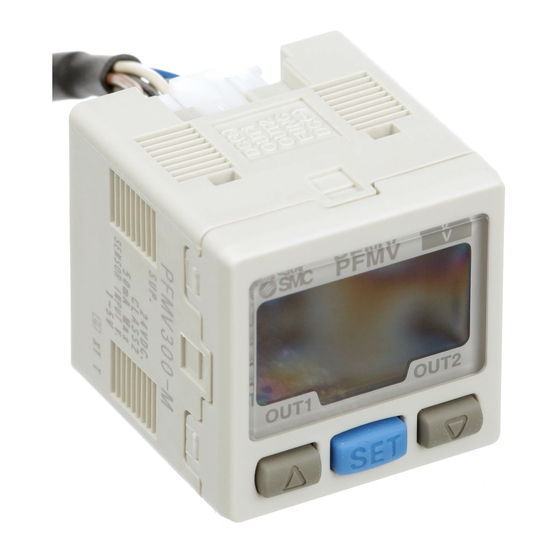
Summary of Product parts Front Item Description Displays the flow value, setting mode, and error indication. LCD Display Four display modes can be selected: display always in red or green, or display changing from green to red, or red to green, according to the output status (OUT1). Indicator LED (OUT1) Indicates the output status of OUT1. -
Page 14: Definition And Terminology
■Definition and terminology Terminology Definition A type of variable output that has a value proportional to the measured quantity. When the analogue output is in the range of 1 to Analogue output 5 V or 4 to 20 mA, it will vary continuously, following the change of flow. - Page 15 Terminology Definition The condition in which the digital display turns off and current Power saving mode consumption is reduced. The flow range within which the product will meet all published Rated flow range specifications. Reproducibility of the display or analogue output value, when the Repeatability measured quantity is repeatedly increased and decreased The time from when the flow is applied as a step input (when the flow...
-
Page 16: Mounting And Installation
Mounting and Installation ■Installation Panel mounting Fix the panel mount adapter to the monitor with the mounting screws (M3x8 L) supplied. The monitor can be mounted on a panel with a thickness of 0.5 to 6.0 mm. Refer to the dimension drawing (page 54) for panel cut-out dimensions. Note when removing the monitor The flow monitor with panel mount adapter can be removed from the installation by removing 2 screws and releasing the hooks at the sides, as illustrated. - Page 17 Bracket mounting Mount the bracket using the mounting screws (M3 x 5 L) supplied. The required tightening torque is 0.5 to 0.7 Nm. Install the product (with bracket) using the M4 screws (2 pcs.). Bracket thickness is approximately 1.6 mm. Refer to the dimension drawing of the bracket (page 55) for mounting hole dimensions.
-
Page 18: Wiring
■Wiring Wiring of connector Connections should only be made with the power supply turned off. Use separate routes for the product wiring and any power or high voltage wiring. Otherwise, malfunction may result due to noise. Ensure that the FG terminal is connected to ground when using a commercially available switch-mode power supply. - Page 19 Connecting/Disconnecting When mounting the connector, insert it straight into the socket, holding the lever and connector body, and push the connector until the lever hooks into the housing, and locks. When removing the connector, press down the lever to release the hook from the housing and pull the connector straight out.
- Page 20 Internal voltage drop: 1 V or less Analogue output: 1 to 5 V Output impedance: approx. 1 kΩ PFMV301 NPN (2 outputs) + Analogue (4 to 20 mA) output type Max. 30 V, 80 mA Internal voltage drop: 1 V or less Analogue output: 4 to 20 mA Max.
- Page 21 PFMV303 PNP (2 outputs) + Analogue (1 to 5 V) output type Max. 80 mA Internal voltage drop: 1 V or less Analogue output: 1 to 5 V Output impedance: approx. 1 kΩ PFMV304 PNP (2 outputs) + Analogue (4 to 20 mA) output type Max.
-
Page 22: Flow Setting
Flow Setting Measurement mode The mode in which the flow is detected and displayed, and the switch function is operating. This is the basic operating mode; other modes should be selected for set-point and other Function Setting changes. : The display will indicate [LLL] if a sensor is not connected. To use the product for flow rate indication, select the connected flow sensor using function [F95] before setting any other functions. - Page 23 <Operation> : The Product outputs will continue operating during setting. 1. Press the button in measurement mode to display the set values. [P_1] or [n_1] and the set value are displayed in turn. : [LLL] is displayed during measurement mode when the sensor is not connected. 2.
-
Page 24: Function Setting
Function Setting Function selection mode In measurement mode, press the button for 2 seconds or longer, to display [F 0]. The [F ] indicates the mode for changing each function setting. Press the button for 2 seconds or longer in function selection mode to return to measurement mode. ■Default setting Item Default setting... -
Page 25: F0 Auto-Preset
■[F 0] Auto-preset This function is capable of calculating the approximate set value automatically based on the on-going operation. <Operation> Press the button in t function selection mode to display [F 0]. Press the button. Set auto-preset Press the button. Return to function selection mode. - Page 26 ●In auto-preset mode, the set value can be automatically calculated and stored. Auto preset is a function to automatically calculate the approximate set values according to the actual operating condition. If the button is pressed during measurement mode after auto-preset function is selected, the display will appear as shown in the table below.
-
Page 27: F1 Setting Of Out1
■[F 1] Setting of OUT1 Set output method of OUT1. To use flow indication, select the flow sensor at [F95] selection of flow indication before setting the function. <Operation> Press the button in function selection mode to display [F 1]. Press the button. - Page 28 Input of set values Set flow based on setting operation on page Hysteresis mode: [n_1] Window comparator mode: [n1L] [n1H] : For normal output, n becomes P. Press the button. Setting of hysteresis [H_1] and the set value are displayed in turn Press the button to input.
- Page 29 ●List of output modes : If hysteresis or window comparator mode is selected and there is an unstable flow condition (due to fluid pulsation, for example), unstable output operation can result. In such situations, keep sufficient margin between the set values and confirm that the output operation stabilizes. -28- No.PF※※-OMN0005-E...
-
Page 30: F2 Setting Of Out2
■[F 2] Setting of OUT2 Set output method of OUT2. The display colour is linked to the setting of OUT1, and can not be set for OUT2. To use flow indication, select the flow sensor at [F95] selection of flow indication before setting the function. <Operation>... -
Page 31: F3 Response Time
■[F 3] Response time Select the response time of the switch output. Output chattering can be prevented by setting the response time. <Operation> Press the button in function selection mode to display [F 3]. Press the button. Select response time [rES] and the set value are displayed in turn. -
Page 32: F4 External Input
■[F 4] External input This function is available when the product includes the external input function : When using a product without external input function, [---] is displayed and this function cannot be set. To use flow indication, select the flow sensor at [F95] selection of flow indication before setting the function. Selection of flow indication changes the selected content of the external input function. - Page 33 Voltage indication ●Auto-shift: Function to perform output to relative voltage change referring the voltage value on the display when signal is input. : If PFMV5□ series (single direction) is selected, operation is based on 1.00 V (=sensor output value when the flow is zero.) If PFMV5□F series (dual directional) is selected, operation is based on 3.00 V (=sensor output value when the flow is zero.) ●Input signal: Connect input wire to GND for 5 ms or longer <Operation>...
- Page 34 Flow indication ●Auto-shift: Function to perform output to relative flow change referring the instantaneous flow when signal is input. ●Auto-shift zero: Function to perform output to relative change and clear the display value as zero referring the instantaneous flow when signal is input. Input signal: Connect input wire to GND for 5 ms or longer <Operation>...
- Page 35 ●Operation example of auto-shift (When voltage indication mode) Voltage indication <Ex.> This function is used during the confirmation of adsorption/release as a solution for voltage (=flow rate) change due to source pressure fluctuation or nozzle diameter change. When auto-shift function is not used, even if the work is adsorbed, switching operation is not made when the voltage (=flow rate) amount fluctuates.
- Page 36 Setting range when auto-shift function is selected is -4.40 to 4.40. If relative set value after the auto-shift is out of upper or lower limit, this monitor operates with upper limit (5.10) or lower limit (0.70). : When flow indication mode is selected, flow setting range when external input is selected is changed. <Ex.>...
-
Page 37: F5 Power Saving Mode
■[F 5] Power saving mode In power saving mode, the display can be turned off to reduce power consumption. When the product is left for 30 seconds with no button operations, it will enter power saving mode. The decimal point flashes during operation. <Operation>... -
Page 38: F6 Security Code
■[F 6] Security code A security code can be selected, which must be entered to unlock the keys when the keys are locked. Refer to key-lock function (page 42). <Operation> Press the button in function selection mode to display [F 6]. Press the button Select security code... -
Page 39: F95 Selection Of Flow Indication
■[F95] Selection of flow indication The flow rate can be displayed. The flow rate units can be selected (for models with unit selection function) after selecting the connected sensor. L/min or CFM (ft /min) ×10 are the selectable display units. To use for flow rate indication, select the sensor and units before setting the functions [F1], [F2], [F4]. - Page 40 Flow unit selection is available only the product with the unit selection function. Unit selection function [Uni] and the set value are displayed in turn. Press the button to select flow range. Press the button. Return to function selection mode. Selection of flow indication [F95] completed...
-
Page 41: F99 Reset To The Default Setting
■[F99] Reset to the default settings The factory default settings can be restored. <Operation> Press the button in function selection mode to display [F99]. Press the button. Reset to the default setting [ini] and the set value are displayed in turn. Press the button to select. -
Page 42: Other Setting
Other Setting ●Standard value offset function If the displayed value can be 1.00 due to the deviation in each product, the displayed value can be forcibly changed to 1.00 for PFMV505, 510 and 530. During flow indication, the displayed valve can be forcibly change to 0.00. For PFMV505F, 510F and 530F, the forcibly changed value will be 3.00. - Page 43 ●Key Lock The key lock function is used to prevent errors occurring due to unintentional changes of the set values. If a button operation is performed while the key lock setting is ON, [LoC] is displayed for approximately 1 second. <Operation -without security code input- >...
- Page 44 <Operation -with security code input- > Locking 1. Press the button for 5 seconds or longer in measurement mode. [UnL] will be displayed. 2. Press the button to select keys lock [LoC]. 3. Press the button to store the setting and return to measurement mode. Unlocking 1.
- Page 45 ●How to change the security code At the time of shipment, the security code is set to [000], but this can be changed to any number. <Operation> 1. Perform the key locking procedure, followed by the first 3 steps of the key unlocking procedure 2.
-
Page 46: Maintenance
Maintenance How to reset the product after a power cut forcible de-energizing The setting of the product will be retained as it was before a power cut or de-energizing. The output condition is also basically recovered to that before a power cut or de-energizing, but may change depending on the operating environment. -
Page 47: Troubleshooting
Troubleshooting Troubleshooting If an operation failure occurs with the product, use the chart below to find out the cause of the problem. If none of the countermeasures seem to be applicable, or a replacement product operates normally when installed, the product may be faulty. A product can be damaged by the operating environment (system configuration etc). - Page 48 Fault Status Possible cause Item to check Countermeasure Foreign matter (1) Check if any foreign matter has entered the has entered the flow Install a filter or mist separator flow passage or passage. on the IN side. adhered to the (2) Check if there is foreign sensor matter on the mesh.
- Page 49 Fault Status Possible cause Item to check Countermeasure Check that the brown, blue, Incorrect wiring black and white wires are Correct the wiring. connected correctly. No output Connector is Correct the connector Check the connectors. disconnected wiring. Foreign matter (1) Check if any foreign matter has entered the has entered the flow Install a filter or mist separator...
-
Page 50: Error Indication
■Error indication Error Name Display Type Troubleshooting The flow (input voltage) has exceeded Reduce input voltage the upper limit of the display range. (= flow). Input voltage flow The flow (input voltage) is less than the Increase input voltage error lower limit of the display range. -
Page 51: Specifications
Specifications ■Specifications PFMV3□□ Model Applicable sensor PFMV505 PFMV510 PFMV530 PFMV505F PFMV510F PFMV530F Rated voltage 1.00 to 5.00 V range Display voltage range 0.70 to 5.10 V Voltage Set voltage range Minimum setting 0.01V unit Rated flow 0 to 0.5 -0.05 to 0.5 to 0.5 -1 to -1 0 to 3 L/min... - Page 52 PFMV3□□ Model Enclosure IP40 Operating Operating: 0 to 50 C; stored: -10 to 60 C (no frezzing or condensation) temp. range Operating Operating and stored: 35 to 85% R.H. (no condensation) humidity range Environment Withstand 1000 VAC for 1 min. between whole charging part and case voltage Insulation 50 MΩ...
-
Page 53: Characteristics Data
■Characteristics data ●Analogue output characteristics Voltage display Flow display Model Min. rated flow range Max. rated flow range PFMV505 0 L/min 0.5 L/min PFMV510 0 L/min 1.0 L/min PFMV530 0 L/min 3.0 L/min PFMV505F -0.5 L/min 0.5 L/min PFMV510F -1.0 L/min 1.0 L/min PFMV530F -3.0 L/min... - Page 54 ●Display accuracy and repeatability for combination with each appropriate sensor when the flow indication is selected. -53- No.PF※※-OMN0005-E...
-
Page 55: Dimensions
■Dimensions (in mm) PFMV3※ ※ Panel cut-out dimensions Panel thickness: 0.5 to 6.0 mm ●Individual ●Two or more in a row (n: The number of products) Horizontal Vertical : Ensure all corners are a maximum of R3. If a bend (R) is used, limit it to R2 or less. -54- No.PF※※-OMN0005-E... - Page 56 Bracket (ZS-28-B) Power and output lead wire and connector (ZS-28-A) -55- No.PF※※-OMN0005-E...
- Page 57 Revision history A: Contents revised in several places. B: Error correction. (page 28) C: Contents revised in several places. D: Contents revised in several places. [September 2016] E: Contents revised in several places. [August 2018] 4-14-1, Sotokanda, Chiyoda-ku, Tokyo 101-0021 JAPAN Tel: + 81 3 5207 8249 Fax: +81 3 5298 5362 http://www.smcworld.com Note:...
Need help?
Do you have a question about the PFMV301 and is the answer not in the manual?
Questions and answers