
Subscribe to Our Youtube Channel
Related Manuals for SMC Networks Prime-600


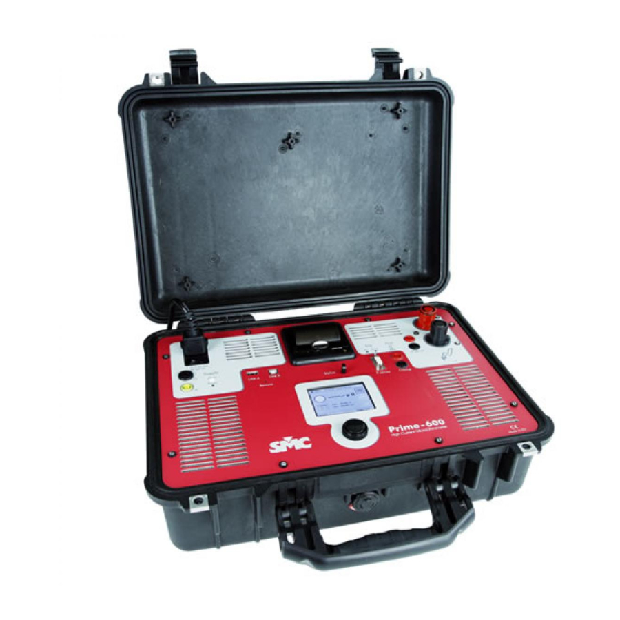
Summary of Contents for SMC Networks Prime-600
- Page 1 Micro-Ohmmeter 600 User Guide Prime - 600 Reference: HAFMU02 Published: 4 July 2016 Version: 3...
- Page 2 Prime - 600 Quality is the focal point of EuroSMC, S.A.’s activity, aimed at fully satisfying its customers’ needs and expectations DISCLAIMER EuroSMC, S.A. does not acknowledge any contractual bond derived from the information, including product characteristics and technical data, included in this document.
-
Page 3: Limited Warranty
User Guide LIMITED WARRANTY This product is guaranteed against defects in materials and manufacture of the actual product for a period of 12 months as from the date the product is registered. If the product is not registered within 30 days after the shipping date, that date will be considered as the start of the warranty period. - Page 4 Prime - 600...
-
Page 5: Table Of Contents
User Guide CONTENT LIMITED WARRANTY ....................3 TRANSPORT CONDITIONS ............... 3 HOW TO ACTIVATE THIS WARRANTY ..........3 CONTENT ......................5 DECLARATION OF CONFORMITY ................8 Manufacturer.................. 8 Declaration of Conformity ............... 8 Standards used................8 ELEMENTS THAT MAKE UP THE SYSTEM ..............10 SAFE USE OF EQUIPMENT .................. - Page 6 Prime - 600 Steps to be followed to perform the test: ..........28 Result: ....................28 “Dynamic” work mode (Dynamic resistance)........29 Setup: ....................29 Steps to be followed to perform the test: ..........31 Result: ....................31 “Manual Seq” Work mode (Manual static resistance measurement sequence).
- Page 7 User Guide Installation..................... 55 Connect Prime – 600 to PC..............55 User interface..................56 Action bar....................57 Status bar ..................... 58 Preparation to update the equipment ............. 58 Manual equipment updating..............59 Automatic equipment updating.............. 59 Remote connection setting by Ethernet (bridge mode).....
-
Page 8: Declaration Of Conformity
Prime - 600 DECLARATION OF CONFORMITY For the Prime – 600 system, being applicable to all the elements that comprise Manufacturer EuroSMC, S.A. Pol. Industrial P-29 C/Buril, 69 28400 Collado Villalba Madrid - Spain Declaration of Conformity Based on the results of the tests performed according to appropriate standards, the product meets: ... - Page 9 User Guide Basic IEC 61000-3-2 (2006) Electromagnetic compatibility (EMC) Limits - Limits for harmonic current emissions . IEC 61000-3-3 (2009) Electromagnetic compatibility( EMC). Limits. Limitation of voltage changes, voltage fluctuations and flicker . IEC 61000-4-2/3/4/5/8/11 Electromagnetic compatibility(EMC). Testing and measurement techniques. The tests have been performed in a standard configuration.
-
Page 10: Elements That Make Up The System
Prime - 600 ELEMENTS THAT MAKE UP THE SYSTEM Depending on the system you have purchased, you will find the following components: Prime – 600. 1 x Unit High current 1 x 3 m Cable with black connector cables . 1 x 3 m Cable with red connector Measurement 1 x 3 m Red Banana-Banana cable... -
Page 11: Safe Use Of Equipment
User Guide Optional accessories: Nylon bag for Prime – 600. 10 m High current cables 10 m Measurement cables 3m or 10m temperature probe. Ammeter clamp set with 2 m. extension cable. Rigid transport box. SAFE USE OF EQUIPMENT Before using the equipment please carefully read this manual, especially this... -
Page 12: Hazardous Situations For The User And For The Prime - 600 System
Prime - 600 Hazardous situations for the user and for the Prime – 600 system Hazard – Before making any change to the power or measurement connections, make sure that the system is not injecting. Hazard – Following a high current injection, the hoses and connections may be very hot and may cause burns. -
Page 13: Introduction
User Guide INTRODUCTION The Primer – 600 marks the differences with any other equipment that exists today. Its innovative design and cutting-edge technology permit tackling resistance measurement tasks in a much more efficient manner, as it takes the concept of manageability to extremes that have never been possible until now. With Prime –... -
Page 14: Location Of Elements
Prime - 600 LOCATION OF ELEMENTS Power supply panel communications Printer Injection and measurement panel Console... -
Page 15: Prime - 600 (Power Supply Panel And Communications)
User Guide Prime - 600 (Power supply panel and communications) 25-amp fuse. Ground tap. USB-A host. Used to be able to connect a memory stick and save – recuperate reports. USB-B device. Used to be able to update the equipment software and carry out other steps from a PC. -
Page 16: Prime - 600 (Measurement Panel)
Prime - 600 Prime – 600 (Measurement panel). External temperature measurement. Temperature 4-20 mA optical transducer input. Used compensate resistance measurement according to the temperature. Clamp measurement connection. “Dual Ground Clamp” live measurement input. Its function is to compensate the current that leaks to ground when calculating the resistance. -
Page 17: Prime - 600 (A First Glimpse Of The Console)
User Guide Prime – 600 (A first glimpse of the console). Indicates which USB port is active Date and time Disconnected measurement connections indicator Test start / stop button Print out test Save test Indicates the selected current injection Indicates the selected work mode... - Page 18 Prime - 600 Instant measurements of: Current that is being injected (Iout). Voltage that is being measured in “V sense” connections (Vsns). Current that is being measured in the “Clamp” connections (Iclamp). Access to different menus External temperature measurement indicator Connected power indicator.
-
Page 19: How To Connect The System
User Guide HOW TO CONNECT THE SYSTEM The Prime system will be comprised of at least a couple of high current cables, a couple of voltage measurement cables and a couple of crocodile clips. Making the connections. Before continuing, make sure that the on/off switch of the unit is in its Disconnected position. -
Page 20: Preparing Optional Accessories
Prime - 600 Preparing optional accessories. The ammeter clamp, supplied as an optional accessory by EuroSMC, will be connected to the “Clamp” connections. The temperature optical sensor, supplied as an optional accessory by EuroSMC, will be connected in the “T Sense” connector. TURNING ON THE SYSTEM Apply the power switch of your Prime –... -
Page 21: Other Status Indicators
User Guide After turning on the system, this reboots and the first thing displayed on the screen is the logotype and software version of the equipment. Once rebooted, the current setup of the equipment is graphically shown on the identification screen. -
Page 22: Setup Menus From The Main Touch Screen
Prime - 600 Setup Menus from the main touch screen Date and time setup menu Adjust with rotary dial and pushbutton Exit menu Validate adjustment Printing out test. If a test ends successfully, this is automatically enabled and it can be printed. - Page 23 User Guide Keep pressed (~3 seconds), if you want to make a print-out with a heading. You can enter a description of the test. The content of the printed results will be explained in detail later on in this manual. Delete Select with rotary dial and...
- Page 24 Prime - 600 Select with rotary Delete dial and pushbutton Eliminate text Exit menu Save Work mode setup menu. This menu will be explained in detail later on in this manual. Injection setup menu. Enable “Dual Select current that Ground Clamp” test will be performed function Validate...
- Page 25 User Guide Setup options menu. Select *Report language menu Exit menu MAINTENANCE Firmware Touch calibration version Hardware *Update version firmware Equipment Exit menu serial no. * This menu will be explained in detail later on in this manual . External temperature measurement indicator. This is automatically activated when the optical temperature transducer is connected.
-
Page 26: Performing Tests
Prime - 600 Resistance range setup. Auto range mode Exit menu Validate range PERFORMING TESTS The setup prior to performing a test is summed up as: Selection of work mode. Selection of current to inject. Selection of resistance range. “Single”... - Page 27 User Guide Access the work mode menu Select Single Validate Exit menu selection * Burning Time: time in seconds, to acquire data once the injection has reached the requested current. Access the current injection menu. Enter the current value that adapts to the device tested. ...
-
Page 28: Steps To Be Followed To Perform The Test
Prime - 600 Steps to be followed to perform the test: Connect the crocodile clips of the high current cables to the current taps of the device tested. Connect the voltage measurement cables to the appropriate sensing connections of the device tested. Perform the test by pressing The equipment will indicate start of current injection with two beeps and the end with one beep. -
Page 29: Dynamic" Work Mode (Dynamic Resistance)
User Guide Print out the test result. Header Indicates equipment serial no. (S/N) and firmware version (V.) Indicates work mode, date and time, and description, entered by the user, for the test Test setup Averaged test result “Dynamic” work mode (Dynamic resistance). We will select this work mode when we need to study, over time, the behaviour of the contact resistance during the opening of a switch. - Page 30 Prime - 600 Access the work mode menu. Select Dynamic Validate Exit menu selection * Burning T.Out: time, in seconds, available, after stable measurement acquisition, to manually activate the switch. Samples Avg. (1…255) f.sampling 30KSPS Filtering Result Max. 255 Test ( 1 / 30KSPS ) X 255 X 255 time * Samples Avg: Prime –...
-
Page 31: Steps To Be Followed To Perform The Test
User Guide Access the current injection menu. Enter the current value that adapts to the device tested. You can set up the “Dual Ground Clamp” functionality. This functionality will be explained in detail later on in this manual. Access the resistance range menu. - Page 32 Prime - 600 Save the test result. Zoom Print (Press on the grid) Save Access results table * N: Test sample number. (Explore table by operating the rotary dial) Access main screen Access chart...
- Page 33 User Guide Print out the test result Header Indicates equipment serial no. (S/N) and firmware version (V.) Indicates work mode, date and time, and description, entered by the user, for the test Test setup Test chart...
-
Page 34: Manual Seq" Work Mode (Manual Static Resistance Measurement Sequence)
Prime - 600 “Manual Seq” Work mode (Manual static resistance measurement sequence). We will select this work mode when we wish to measure several resistances automatically and with precision in one same test. Setup: Connect the high current cables to the current taps of the Prime - 600. Connect the measurement cables to the voltage measurement connections of the Prime - 600. -
Page 35: Steps To Be Followed To Perform The Test
User Guide Access the current injection menu. Enter the current value that adapts to the device tested. You can set up the “Dual Ground Clamp” functionality. This functionality will be explained in detail later on in this manual. Access the resistance range menu. -
Page 36: Result
Prime - 600 This sequence will be repeated as often as required by the user. If the user wishes to end the test, he/she must press If the “Waiting T.Out” selected is exceeded, the test will automatically abort in an incorrect manner. Result: When the test has ended successfully, the result will be shown on a table. - Page 37 User Guide The following will be possible from the main screen: Save the result of the test by pressing. Print out the result of the test by pressing. Header Indicates equipment serial no. (S/N) and firmware version (V.) Indicates work mode, date and time, and description, entered by the user, for the test Test setup...
-
Page 38: Auto Seq" Work Mode (Automatic Static Resistance Measurement Sequence)
Prime - 600 “Auto Seq” Work mode (Automatic static resistance measurement sequence). We will select this work mode when we wish to measure the same resistance with precision and with a certain sequence. Setup: Connect the high current cables to the current taps of the Prime - 600. Connect the measurement cables to the voltage measurement connections of the Prime - 600. -
Page 39: Steps To Be Followed To Perform The Test
User Guide Access the current injection menu. Enter the current value that adapts to the device tested. You can set up the “Dual Ground Clamp” functionality. This functionality will be explained in detail later on in this manual. Access the resistance range menu. -
Page 40: Result
Prime - 600 Out, The red indicator, will remain on until the test sequence ends. When the sequence has ended, the current injection indicators will go off and this will be indicated with one beep. Result: When the test has ended successfully, the result will be shown on a table. * N: Test measurement number. - Page 41 User Guide Print out the result of the test Header Indicates equipment serial no. (S/N) and firmware version (V.) Indicates work mode, date and time, and description, entered by the user, for the test Test setup Results table Test chart...
-
Page 42: Advanced Settings
Prime - 600 ADVANCED SETTINGS The accessories used in these settings are optional, supplied by EuroSMC. Dual Ground Clamp” The Prime - 600 permits working with dual grounding. This system measures the part of the current that circulates through the ground circuit and eliminates it accurately and instantaneously from the calculation of the resistance. -
Page 43: Diagram Connection Diagram To Perform The Test
User Guide Enter the current value that adapts to the device tested Validate selection Exit menu * Enable Dual Ground Clamp: Enable function. *Sensitivity: Set the ammeter clamp measurement range that is going to be used . If the ammeter clamp supplied by EuroSMC is used, the available ranges will be 1mV/A and 10mv/A. -
Page 44: Steps To Be Followed To Perform The Test
Prime - 600 Steps to be followed to perform the test: After setting the work mode and making the connections, perform the test by pressing The equipment will indicate the start of current injection with two beeps and the end with one beep. For greater safety, el Prime –... -
Page 45: Thermal Compensation Of The Device Tested,"T.sense
User Guide Thermal compensation of the device tested,“T.Sense”. The optical transducer will transmit the temperature value of the point measured in each test to Prime – 600. Thus, the user can standardise the resistances measured at a standard temperature, for example 75º C, to present them on his/her report. -
Page 46: Steps To Be Followed To Perform The Test
Prime - 600 Connect the optical transducer supplied by EurSMC as an optional accessories, to the “T Sense” connection of the Prime - 600. On red, it indicates that the transducer is connected Validate Exit menu selection * With transducer connected, the window is activated to set its parameters. -
Page 47: Result
User Guide Orientate the transducer towards the device tested. The distance at which it must be located will depend on the area to be measured. Follow the diagram below, as reference. Start the test by pressing The equipment will indicate the start of current injection with two beeps and the end with one beep. -
Page 48: Obtaining Test Reports
Prime - 600 OBTAINING TEST REPORTS The Prime – 600 system has the capacity to directly print out the test results and save them for later review, by means of the PrimeSync program (for PC), or save them to recuperate them later on in the equipment console. Reporting and testing concept Testing refers to each one of the tests performed, including: the measurements that are set to be shown on the screen;... -
Page 49: Using The Primesync Program To Manage Tests And Reports
User Guide Memory stick inserted into host USB-A Eliminate test Copy tests between internal memory and Load memory stick test Select internal memory Cancel Exit menu * Selected test no. / Total no. of tests. Test titer. * Work mode used to carry out the test. * Date and time of moment the test was performed. -
Page 50: Test Display
Prime - 600 Test display. If you have chosen the option to save the tests on a memory stick, these stored tests can be displayed with the PrimeSync application. Open test allows you to select one or several tests to be PrimeSync displayed on the application. -
Page 51: Graphic Display
User Guide There will be the same number of tabs as tests loaded Test heading. Includes, among others, name, description and date. Includes equipment adjustment at time the test is performed. Test results. They can be shown in individual controls or in list format. - Page 52 Prime - 600 Press left button of mouse and, keeping it pressed, drag the cursor until you have selected the area of the chart to be enlarged Release the mouse button.The enlarged area of the chart will be shown. Pressing with the right button of the mouse on the chart, a menu will...
-
Page 53: Report Setting Options
User Guide Report setting options Report settings allows you to personalise some parameters of the report. To be able to choose which ones, press the button or its equivalent in the Reports/ Report settings menu. Text that will appear on the report heading, normally the company name Select tests to be... -
Page 54: Report Preview
Prime - 600 Report preview. Show test preview . This shows a preview of the tests selected for later printing or to generate PDF, HTML, Excel file, among others, from this same report preview. Available options to generate a report Report generation. -
Page 55: Settings And Maintenance
User Guide SETTINGS AND MAINTENANCE PrimeSync program (for PC with Windows). Installation. The PrimeSync application is an auxiliary tool of the Prime – 600 system, whose purpose is to provide a better view of the tests performed with the equipment as well as carry out check and maintenance tasks. -
Page 56: User Interface
Prime - 600 User interface Click on the icon that will have appeared on your desktop and execute the program. When it starts up, the PrimeSync application will show a window similar to that below: Action bar Display tests Status bar... -
Page 57: Action Bar
User Guide Action bar Open test. This opens one or several tests performed with Prime – 600 for them to be displayed. Close test. This closes the test that is displayed on screen. This action button would be disabled if no test is open. Prime –... -
Page 58: Status Bar
Prime - 600 Status bar This shows the information about the connection status with the Prime – 600. Prime – 600 is not connected by the USB cable to the PrimeSync PC where is executed. Prime – 600 is connected in normal work mode. Prime –... -
Page 59: Manual Equipment Updating
User Guide Manual equipment updating. To carry out the updating, the Prime – 600 must be in programming mode. If you press this button of the action bar to program, you can select the file with the new firmware to be updated. After pressing it, the file explorer opens. - Page 60 Prime - 600 When the Prime – 600 is connected to the PC in normal work mode (not in programming mode), a consultation is made, among other things, about the equipment firmware version. If a more recent version exists, the following indication will appear: To update to the new version Click with the left button of the mouse on the indicator with the new...
-
Page 61: Remote Connection Setting By Ethernet (Bridge Mode)
User Guide This reminds us of the (necessary) process to establish the programming model. Prime – 600 in Carry out the steps indicated. This process can be accessed, too, by pressing this button on “Maintenance” the settings options menu, in the tab of the Prime - 600 After entering the Prime –... -
Page 62: Maintenance Of The Prime - 600 Equipment From Primesync
Prime - 600 The settings window will show the following settings: * Select local network adapter. This permits selecting the network adapter, based on its IP address. All the addresses are shown on a dropdown list * Remote HOST in bridge mode. This selects the remote address (host) to connect to and to send the Prime –... -
Page 63: Updating The Primesync Program
User Guide Updating the Primesync program. To check if there is a new version of the program, you will have to access the program aid menu “?/Check update”. If a new version is available A request will be made to download it and you will be able to choose the folder where you wish to save the new executable. -
Page 64: Problems That Might Arise
Prime - 600 PROBLEMS THAT MIGHT ARISE... -
Page 65: Specifications
User Guide SPECIFICATIONS Prime – 600. Sample Rate (Max.): 30 kSPS – Temp.: 10 ~ 40ºC STATIC RESISTANCE MEASUREMENT RANGE RESOLUTION PRECISION 1000.0µΩ 10.0µΩ < R ≤ 100.0µΩ (150 ~ 600A): ± 0.3µΩ 0.1µΩ 100.0µΩ < R ≤ 1000.0µΩ (20 ~ 600A): ±... -
Page 66: Prime - 600: Typical High Current D.c. Power Output (English Only)
Prime - 600 Prime ‐ 600: Typical High Current D.C. Power Output (English only). Line Supply High Current Connection Leads I out V load R load R Measurable Max.(mΩ) (V.a.c,F=50Hz) Max.(mΩ) Max.(V) Standard 2x3m/35mm 12.33 2465 1000 High Flexibility Crocodile 10.18 67.9 40.0... -
Page 67: Order Information
User Guide Order Information ORDER INFORMATION SYSTEM SETUP Prime – 600. 1 x Unit ACCESSORIES INCLUDED 3 m high current cable with black connector 3m 3 m high current cable with red connector 3 m red Banana-Banana cable 3 m black Banana-Banana cable Red crocodile clip Black crocodile clip Red test tip... - Page 68 Prime - 600 OPTIONAL ACCESSORIES Nylon bag for Prime – 600 BAG 15 CBL11-PRIME-600-I 10 m high current cables CBL11-PRIME-600-M 10 m measurement cables PME-VCLMP Set of 2 clamps voltage measurement firm grip for Prime - 600 PME-TMP-SNS10 10 m temperature probe...
Need help?
Do you have a question about the Prime-600 and is the answer not in the manual?
Questions and answers