Advertisement
Quick Links
PPA-TF2Z064EN
ORIGINAL INSTRUCTIONS
Instruction Manual
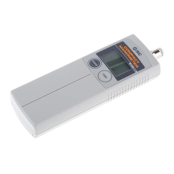
Compact Manometer
PPA100 / PPA101 / PPA102
The intended use of this product is for pressure measurement.
1 Safety Instructions
These safety instructions are intended to prevent hazardous situations
and/or equipment damage. These instructions indicate the level of
potential hazard with the labels of "Caution," "Warning" or "Danger."
They are all important notes for safety and must be followed in addition
*1)
to International Standards (ISO/IEC)
, and other safety regulations.
*1)
ISO 4414: Pneumatic fluid power - General rules relating to systems.
ISO 4413: Hydraulic fluid power - General rules relating to systems.
IEC 60204-1: Safety of machinery - Electrical equipment of machines.
(Part 1: General requirements)
ISO 10218-1: Robots and robotic devices - Safety requirements for
industrial robots - Part 1: Robots.
• Refer to product catalogue, Operation Manual and Handling
Precautions for SMC Products for additional information.
• Keep this manual in a safe place for future reference.
Caution indicates a hazard with a low level of risk which, if
Caution
not avoided, could result in minor or moderate injury.
Warning indicates a hazard with a medium level of risk
Warning
which, if not avoided, could result in death or serious injury.
Danger indicates a hazard with a high level of risk which, if
Danger
not avoided, will result in death or serious injury.
Warning
• Always ensure compliance with relevant safety laws and
standards.
• All work must be carried out in a safe manner by a qualified person in
compliance with applicable national regulations.
• Refer to the operation manual or catalogue on the SMC website (URL:
https://www.smcworld.com) for further Safety Instructions.
2 Specifications
2.1 General specifications
PPA100
PPA101
PPA102
Model
High pressure
Vacuum
Low pressure
-0.1 to 1
-101 to 10
-10 to 100
Rated pressure range
MPa
kPa
kPa
Display method
3 digit LCD with backlight
Pressure display
1/100
discrimination
kPa
-
1
MPa
0.01
-
mmHg
-
5
Minimum
2
display
kgf/cm
0.1
0.01
0.01
unit
inHg
-
0.2
psi
1
0.1
bar
0.1
0.01
0.01
Over pressure, Memory data error,
Error display
Change battery sign
Peak / bottom display, backlight, Auto power
Function
OFF, Zero clear, Units display switching
Withstand pressure
1.5 MPa
200 kPa
200 kPa
Applicable fluid
Air, Non-corrosive gases, non-flammable gas
Power supply voltage
3 VDC, Type AA dry cell x 2 pcs.
12 months continuous operation
Battery life
(without backlight, at 25°C)
Response speed
250 ms
Display accuracy
±2% F.S. (at 25°C)
Repeatability
±1% F.S. (at 25°C)
Temperature
±3% F.S. (0 to 50°C with 25°C standard)
characteristics
Connection port size
M5 x 0.8
Operating
0 to 50°C (no condensation)
temperature range
Operating humidity
35 to 85% RH (no condensation)
range
Enclosure rating
IP40
Weight
100 g (Unit: 50 g, Battery: 50 g)
*1) Batteries (manganese R6 or alkaline LR6) not included.
*2) For the type without the unit switching function are fixed to SI units
(kPa or MPa.
*3) With regard to the compatibility condition for EMC, the pressure
display value variation is ±15% F.S. or less.
Warning
Special products (-X) might have specifications different from those
shown in this section. Contact SMC for specific drawings.
3 Installation
3.1 Installation
Warning
• Do not install the product unless the safety instructions have been read
and understood.
3.2 Environment
Warning
• Do not use in an environment where corrosive gases, chemicals, salt
water or steam are present.
• Do not use in an explosive atmosphere.
• Do not expose to direct sunlight. Use a suitable protective cover.
• Do not install in a location subject to vibration or impact in excess of
the product's specifications.
• Do not operate in a location exposed to radiant heat that would result
in temperatures in excess of the product's specifications.
3 Installation (continued)
3.3 Piping
Caution
• Before connecting piping be sure to clean up chips, cutting oil, dust etc.
• When installing piping or fittings, ensure sealant material does not
enter inside the port. When using seal tape, leave 1 thread exposed
on the end of the pipe/fitting.
• Tighten fittings to the specified tightening torque.
1
3.4 Lubrication
-
Caution
-
• SMC products have been lubricated for life at manufacture, and do not
require lubrication in service.
-
• If a lubricant is to be used in the system, refer to catalogue for details.
0.1
4 Settings
4.1 Initial Setting
Perform initial setting when using for the first time and after changing the
batteries, as the unit will display a memory data error.
1. Confirmation of display
When power is applied, if there is nothing on the
display, proceed to step 2.
If "Err" Is displayed on the LCD, switch the power
OFF and ON again. The display should clear.
Proceed to step 2.
2. Press and hold the POWER button for 6 seconds
or more.
The unit will move into the zero-clear mode. When
this happens "CAL" will be displayed.
3. Release the POWER button.
When zero clear is finished, the unit will operate.
4.2 Power ON
Press the POWER button.
The power will turn ON.
When pressed and held for 6 seconds or more the
unit will move into zero-clear mode.
4.3 Power OFF
Press and hold the POWER button for 3 seconds
or more.
The power will turn OFF.
The power will also turn OFF If there is no button
operation for 5 minutes or more (auto power OFF
function).
4.4 Units Display Switching
1.
Press and hold the POWER and LIGHT
buttons for 3 seconds or more.
The units on the LCD display will flash.
2.
Press the LIGHT button
The units will change (refer to the units table).
3.
Press the POWER button
The units are set and the units display
setting is complete.
(For products with units switching function).
4 Settings (continued)
Units available
High pressure
Vacuum pressure
Low pressure
(PPA100)
(PPA101)
(PPA102)
kPa > bar > psi >
MPa > bar > psi > kgf
kPa > bar > psi > kgf
inHg > mmHg
4.5 Peak / Bottom display
Press the POWER button.
• For Peak display
To display the maximum pressure value, with "P"
displayed on the LCD. The display will change if the
pressure exceeds the pressure being held.
Press the POWER button.
• For Bottom display
To display the minimum pressure value, with "b"
displayed on the LCD. The display will change if the
pressure falls below the pressure being held.
Press the POWER to complete the setting.
Since this function is combined with the power OFF operation, the button
should be released when the "P" or "b" is displayed.
4.6 Auto Power OFF function
The power is turned OFF when there has been no
button operation for 5 minutes.
(To cancel this function refer to the lock mode
function below).
4.7 Lock mode function
Press and hold the POWER and LIGHT buttons
for 6 seconds or more.
The lock mode is activated and the auto power OFF
function is cancelled.
"L" is displayed on the LCD display.
When the power is turned OFF the lock mode is
released.
4.8 Turning ON the Backlight
Press the LIGHT button.
The display lights up when the button is pressed.
In lock mode it lights up when pressed and turns
OFF when pressed again.
However the maximum lighting time is
approximately one minute.
4.9 Zero clear function
Press the POWER button for 6 seconds or
more.
The zero displayed at atmospheric pressure can be
automatically adjusted.
This means it is possible to eliminate a display
discrepancy at atmospheric pressure.
1. Turn the power OFF.
2. Release the supply pressure to atmosphere.
3. When the POWER button is pressed and held
for 6 seconds or more the zero clear function is
performed and "CAL" is displayed on the LCD.
Page 1 of 2
Advertisement

Subscribe to Our Youtube Channel
Related Manuals for SMC Networks PPA100


Summary of Contents for SMC Networks PPA100
- Page 1 When using seal tape, leave 1 thread exposed Display method 3 digit LCD with backlight on the end of the pipe/fitting. PPA100 / PPA101 / PPA102 4.5 Peak / Bottom display Pressure display • Tighten fittings to the specified tightening torque.
- Page 2 PPA-TF2Z064EN 5 How to Order 8 Limitations of Use Refer to the operation manual or catalogue on the SMC website (URL: 8.1 Limited warranty and disclaimer/compliance requirements https://www.smcworld.com) for the How to Order information. Refer to Handling Precautions for SMC Products. 6 Outline Dimensions (mm) 9 Product Disposal Refer to the operation manual or catalogue on the SMC website (URL:...
Need help?
Do you have a question about the PPA100 and is the answer not in the manual?
Questions and answers