Table of Contents
Advertisement
Quick Links
Advertisement
Table of Contents

Related Manuals for KNF OEM


Summary of Contents for KNF OEM
- Page 1 KNF 308930-308933 05/19 N1200.12, N1400.1.2.12 TRANSLATION OF ORIGINAL OPERATING AND INSTALLATION INSTRUCTION ENGLISH DIAPHRAGM PUMP Note! Before operating the pump and the accessories, please read the operating and installation instructions and pay attention to the safety precautions!
-
Page 2: Table Of Contents
Index KNF Neuberger GmbH Alter Weg 3 1 About this document ............ 3 79112 Freiburg 2 Use ................... 4 Germany 3 Safety................ 6 Phone +49-(0)7664/5909-0 4 Technical data .............. 8 Fax. 07664/5909-99 5 Design and function ............ 11 6 Transport ................ 13 www.knf.com... -
Page 3: About This Document
An activity to be carried out is specified here (a step). 1. The first step of an activity to be carried out is specified here. This symbol indicates important information. Translation of Original operating and installation instruction, English, KNF 308930-308933 05/19... -
Page 4: Use
Frequency converter Pumps with three-phase motor are designed for operation with frequency converter in the speed range 500 – 1500 rpm (50 Hz) or 600 – 1600 rpm (60 Hz) (see also Chapter 7.2 Electrical connection). Translation of Original operating and installation instruction, English, KNF 308930-308933 05/19... - Page 5 No operating pressure may be applied to the suction side of the pump. Pumps with capacitor motor are not intended for operation with a fre- quency converter. Translation of Original operating and installation instruction, English, KNF 308930-308933 05/19...
-
Page 6: Safety
(4 Technical data). If applicable, also take into consideration external energy sources (e.g., ra- diation sources) that could add heat to the medium. In case of doubt, contact KNF Customer Service. Translation of Original operating and installation instruction, English, KNF 308930-308933 05/19... - Page 7 DIN EN 50581 § EN 60034-30-1 (only pumps with three-phase motor) Customer service and repairs The pumps are maintenance-free. KNF does, however, recommend peri- odically inspecting the pumps for noticeable changes to noises and vibra- tions. Only have repairs to the pumps performed by the responsible KNF Cus- tomer Service.
-
Page 8: Technical Data
Tab. 4 *Acc. to ISO 228 Connection for water cooling Pump type Value N1200.12 Thread size G 1/4* N1400.1.2.12 Thread size G 1/4* Tab. 5 *Acc. to ISO 228 Translation of Original operating and installation instruction, English, KNF 308930-308933 05/19... - Page 9 See operating instructions for motor voltage fluctuations Tab. 7 *For further voltage and frequency variants, see type plate **See type plate Weight Pump type Weight [kg] N1200.12 approx. 60 N1400.1.2.12 approx. 82 Tab. 8 Translation of Original operating and installation instruction, English, KNF 308930-308933 05/19...
- Page 10 For explanation on the task and principle, see Chapter 5 Design and function. à For information on installation and connection, see Chapter 7 Installa- tion and connection. à For information operation, see Chapter 8.1 General. Translation of Original operating and installation instruction, English, KNF 308930-308933 05/19...
-
Page 11: Design And Function
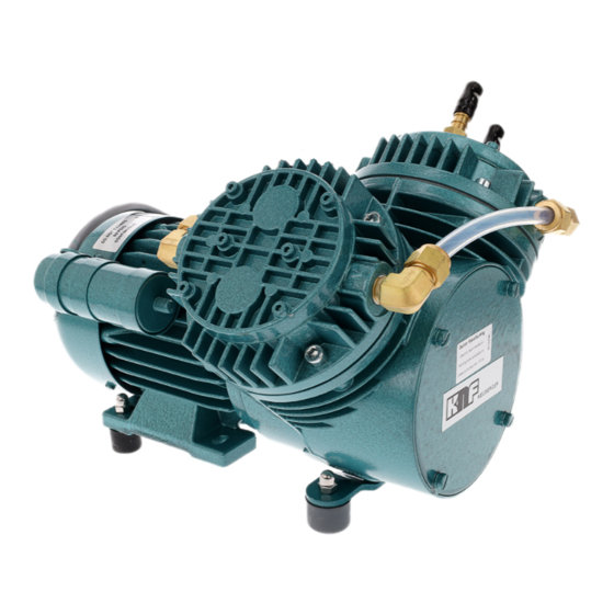
6 Motor fan cover 7 Electrical terminal box 8 Screw plug of the hole for pressure monitoring of the diaphragm innerspace (2x per head) 9 Pneumatic pump outlet Fig. 2 Diaphragm pump N1400.1.2.12 Translation of Original operating and installation instruction, English, KNF 308930-308933 05/19... - Page 12 The closed innerspace (5) between the two diaphragms can be monitored for pressure change with the help of the hole(s) (6) provided for this purpose. Damage to the working diaphragm can thereby be detected immediately. Translation of Original operating and installation instruction, English, KNF 308930-308933 05/19...
-
Page 13: Transport
Store the original packaging of the pump (e.g., for later storage). à Inspect the pump for transport damage after receiving it. à Document any transport damage in writing. à Remove any transport safeguards on the pump prior to commissioning. Translation of Original operating and installation instruction, English, KNF 308930-308933 05/19... - Page 14 Prior to commissioning, make sure that the pump has reached the ambient temperature (4 Technical data). Transport with carrying strap Fig. 4 Position of carrying strap (example) 1. Pull the carrying strap under the pump (see Fig. 4). Fig. 5 Translation of Original operating and installation instruction, English, KNF 308930-308933 05/19...
- Page 15 3. Make certain that the lifting load cannot be transferred from the belt to the pump connection. 4. Lift the pump from the packaging with the help of lifting gear. 5. Lower the pump carefully at the installation location. Translation of Original operating and installation instruction, English, KNF 308930-308933 05/19...
-
Page 16: Installation And Connection
Before installing, store the pump at the installation location to allow it to reach the ambient temperature. Mounting dimensions à For mounting dimensions, see the following figures: Fig. 6 Mounting dimensions pump series N1200.12 Translation of Original operating and installation instruction, English, KNF 308930-308933 05/19... - Page 17 Make sure that the pump is securely attached to the intended fastening holes. If necessary, secure pump to base plate with rubber-bonded metal (see accessories, Chapter 11.2 Accessories; observe details on pump weight, Chapter 4 Technical data). Translation of Original operating and installation instruction, English, KNF 308930-308933 05/19...
- Page 18 (electrical connection). à Fastening the connection cables Fasten the connection cables so that – the cables do not come into contact with movable or hot parts. Translation of Original operating and installation instruction, English, KNF 308930-308933 05/19...
- Page 19 In this way it is possible to prevent the transfer of possible pump vibrations and noises to the system. Translation of Original operating and installation instruction, English, KNF 308930-308933 05/19...
- Page 20 à After breakage of the working diaphragm, the pump must be stopped immediately. Replace the working diaphragm and safety diaphragm prior to further operation (see Chapter 9 Ser- vicing). Translation of Original operating and installation instruction, English, KNF 308930-308933 05/19...
- Page 21 Mounting dimensions For mounting dimensions see Fig. 10, Fig. 11 and Fig. 12: The base plate is shown as an additional accessory on the following dimensional drawings. Fig. 9 Mounting dimensions pump series N1200.12 Translation of Original operating and installation instruction, English, KNF 308930-308933 05/19...
- Page 22 Diaphragm Pump N1200.12, N1400.1.2.12 Fig. 10 Mounting dimensions pump series N1400.1.2.12 à Operate the water connection up to max. 1.0 bar gauge. à Safely drain water discharge. Flow in both directions is permissible. Translation of Original operating and installation instruction, English, KNF 308930-308933 05/19...
-
Page 23: Operation
The pumps are built-in devices. Before they are commissioned, it must be ensured that the machines or systems into which the pumps are in- stalled comply with the relevant provisions. Translation of Original operating and installation instruction, English, KNF 308930-308933 05/19... - Page 24 Further informa- tion is available from the KNF technical adviser (for contact data, see www.knf.de). Risk of dangerous gas mixtures during pump op-...
- Page 25 Recommissioning Before recommissioning, observe the applicable standards, guidelines, regulations and technical standards at the electrical connection. à Inspecting the pump Inspect the pump periodically for external damage or leakage. Translation of Original operating and installation instruction, English, KNF 308930-308933 05/19...
-
Page 26: Servicing
(if necessary for safety reasons: with an inert gas) to ex- tend the service life of the diaphragm. à Discharge the media safely. Translation of Original operating and installation instruction, English, KNF 308930-308933 05/19... - Page 27 Allow the pump and the motor to cool. à Clean the pump and free the pump of hazardous materials. à Remove the hoses/pipes from the pneumatic pump inlet and outlet. Translation of Original operating and installation instruction, English, KNF 308930-308933 05/19...
- Page 28 2 (per pump head) Reed valve 2 (per pump head) Valve stopper 2 (per pump head) Tab. 13 * According to spare parts list, Chapter 11.1 Spare parts Fig. 11 ** According to Translation of Original operating and installation instruction, English, KNF 308930-308933 05/19...
- Page 29 The following item numbers refer to Fig. 11. 26 Screw plug Removing pump head 1. Accessing the fan blades: Loosen fastening screws of the motor fan cover (see Fig. 1 and Fig. 2) and remove cover. Translation of Original operating and installation instruction, English, KNF 308930-308933 05/19...
- Page 30 When remounting, use the exact same number of shim ring(s). 6. Loosen the three hexagon socket head cap screws (9); Remove inter- mediate ring (22). Translation of Original operating and installation instruction, English, KNF 308930-308933 05/19...
- Page 31 Perform steps 1 to 21 for second pump head. Changing reed valves 1. Loosen the two screws (2) and remove valve stopper (3) and reed valves (5) from the intermediate plate (24). Translation of Original operating and installation instruction, English, KNF 308930-308933 05/19...
- Page 32 9. For two-headed pumps: Remount the pneumatic connection between the pump heads. In doing so, retighten the union nuts to the original position (as marked during disassembly, see Fig. 12). Translation of Original operating and installation instruction, English, KNF 308930-308933 05/19...
-
Page 33: Troubleshooting
Thermal switch or triggering device Disconnect pump from electrical mains. for PTC thermistor sensor of the à Allow pump to cool. motor has tripped. à Determine cause of the overheating and rectify. Tab. 15 Translation of Original operating and installation instruction, English, KNF 308930-308933 05/19... - Page 34 2. Clean the pump (see Chapter 9.2.2 Cleaning the pump). 3. Send the pump together with completed Health and Safety Clearance and Decontamination Form to KNF, stating the nature of the trans- ferred medium. Translation of Original operating and installation instruction, English, KNF 308930-308933 05/19...
-
Page 35: Spare Parts And Accessories
N1400.1.2SP.12E 315483 Tab. 18 11.2 Accessories Accessories Order number Water cooling connection: N1200.12 305998 N1400.1.2.12 305445 Suction filter G1/4 316662 Base plate with rubber-bonded metal: 304440 N1200.12 304476 N1400.1.2.12 Tab. 19 Translation of Original operating and installation instruction, English, KNF 308930-308933 05/19... -
Page 36: Returns
Returns Diaphragm Pump N1200.12, N1400.1.2.12 12 Returns Prerequisite for repairing a pump by KNF is a completed Decontamination Form. For customers from Germany, this can be found at: www.knf.de/produkte/ service. For customers from Austria and Switzerland: Please go to website www.knf.com and select your country. -
Page 37: Appendix
Diaphragm Pump N1200.12, N1400.1.2.12 Appendix 13 Appendix See also § Betriebsanleitung Drehstrommotormotor DE-EN.pdf § CE-Erklärung Drehstrommotor DE-EN.pdf Translation of Original operating and installation instruction, English, KNF 308930-308933 05/19... - Page 38 Deutsch / English Betriebsanleitung für Drehstrommotoren (IE2 + IE3 nach IEC 60034-30) Operating Instructions for three-phase-motors (IE2 + IE3 according to IEC 60034-30) Baugröße / HEF IE2 80 L/.. - HEF IE2 355 L/.. Frame size HEF IE3 80 L/.. - HEF IE3 355 L/.. Ausgabe / Edition 07.15 Art.-Nr.
- Page 39 Deutsch Die in dieser Betriebsanleitung enthal- Vor Inbetriebnahme des Motors, nach längerer Lagerungsdauer oder Stillstandzeit (größer 6 Monate), muß der Isolationswiderstand der tenen Sicherheitshinweise sind unbe- Wicklung ermittelt werden. Wicklung mittels Isolationswertmeßgerät dingt zu beachten! (max. Gleichspannung 500 V) gegen Masse prüfen. Sonderausführungen und Bauvarianten können in technischen Ist der Mindest-Isolationswiderstand bei einer Wicklungstemperatur Details von der Grundtype abweichen.
- Page 40 Deutsch / English 3.5 Elektrischer Anschluß Instandhaltung elektrische Anschluß darf durch einen Fachmann Alle Arbeiten am Motor nur im abge- entsprechend den geltenden Sicherheitsvorschriften vorgenommen schalteten, gegen Wiedereinschalten werden. gesicherten Zustand durchführen! Neben den Hauptstromkreisen auch auf Netzspannung und -frequenz müssen mit den Daten auf dem eventuell vorhandene Zusatz-oder Hilfstromkreise, insbesondere Leistungsschild übereinstimmen.
- Page 41 Deutsch / English Ca. 50% des freien Raumes im Lager sowie der Fetträume im Lager- English schild bzw. Lagerdeckel mit Fett der zugelassenen Qualitäten füllen. The safety instructions in this operating Dichtungselemente (z.B. Wellendichtringe) müssen vor dem Zusam- manual are to be observed at all times. menbau auf Funktion sowie Beschädigung überprüft und bei nicht mehr ausreichender Wirksamkeit erneuert werden.
- Page 42 English 2.3 To check the insulation resistance 3.5 Electrical connection The electrical connection may only be performed by a specialist in When measuring insulation accordance with current safety regulations. resistance and immediately afterwards terminals carrying The mains voltage and frequency must comply with the data on the dangerous voltages and must not be touched.
- Page 43 English Fill approx. 50% of the free space in the bearing and the grease Maintenance chambers in the bearing plate and bearing cover with grease of approved quality. Before completing any work on the motor, ensure that it has been switched The sealing elements (eg.
- Page 44 Deutsch / English Anhang / Appendix Bild 1: Schmierstoffe Fig. 1: Lubricants Betriebsbedingungen Wärmeklasse Wälzlagerfett / Einsatzbereich Operating conditions Temperature class Bearing grease / Application / -30 C bis +140 C Normal Baugrößen 80 – 112: Lithiumseifenfett / -20 C bis +140 C Baugrößen 132 –...
- Page 45 Deutsch / English Bild 4: Ersatzteile Fig. 4: Spare parts Teile.-Nr. Bezeichnung Description Part No. Gehäuse (IMB3) Casing (IMB3) Gehäuse ohne Füße (IMB5 / IMB14) Casing without feet (IMB5/IMB14) Motorfüße Motor feet Statorpaket mit Wicklung Stator cove with winding Rotor mit Welle Rotor with shaft 4.0.
- Page 46 Deutsch / English...
- Page 48 KNF worldwide Find your local KNF partner on: www.knf.com...
Need help?
Do you have a question about the OEM and is the answer not in the manual?
Questions and answers