Table of Contents
Advertisement
Quick Links
KNF 121256-121525 08/23
OEM
MINI DIAPHRAGM
VACUUM PUMPS
Note!
Before operating the pump and the accessories, please read the operating instructions on the web site
(www.knf.com/downloads) and pay attention to the safety precautions!
N 84
TRANSLATION OF ORIGINAL OPERATING AND
INSTALLATION INSTRUCTIONS
ENGLISH
Advertisement
Table of Contents

Related Manuals for KNF N 84


Summary of Contents for KNF N 84
- Page 1 KNF 121256-121525 08/23 N 84 TRANSLATION OF ORIGINAL OPERATING AND INSTALLATION INSTRUCTIONS ENGLISH MINI DIAPHRAGM VACUUM PUMPS Note! Before operating the pump and the accessories, please read the operating instructions on the web site (www.knf.com/downloads) and pay attention to the safety precautions!
-
Page 2: Table Of Contents
KNF Neuberger GmbH Alter Weg 3 79112 Freiburg Contents Page Germany 1. About this document ..............3 Phone +49-(0)7664-5909-0 2. Use .................... 4 Fax +49-(0)7664-5909-99 3. Safety ..................5 4. Technical Data ................7 E-mail: info@knf.de 5. Design and function ..............12 www.knf.de... -
Page 3: About This Document
An activity to be carried out (a step) is specified here. 1. The first step of an activity to be carried out is specified here. Additional, consecutively numbered steps follow. This symbol refers to important information. Original-Operating and Installation Instructions, Sprache, KNF 121256-121525 08/23... -
Page 4: Use
The pumps are not suitable for transferring liquids. The pumps are not suitable for use with aggressive media. Other pumps in the KNF product line are designed for use with aggres- sive media. Please contact us for more information. The pumps must not be used to create vacuum and pressure sim- ultaneously. -
Page 5: Safety
“partly completed machinery,” and are therefore to be regarded as not ready for use. Partly completed machinery may not be com- missioned until such time as it has been determined that the ma- Translation of original Operating and Installation Instructions, english, KNF 121256-121525 08/23... - Page 6 EN IEC 63000 EN IEC 63000 EN 60335-1 Tab. 2 Customer services and All repairs to the pump(s) must be carried out by the relevant KNF repairs Customer Service team. Housings with voltage-caring parts may be opened by technical personnel only.
-
Page 7: E-Mail: Info@Knf.de 4. Technical Data
Take all necessary care to prevent this leading to a dangerous situation. Project-specific pumps that are not fitted with a thermal switch must be protected by the user against the risk of overheating. Translation of original Operating and Installation Instructions, english, KNF 121256-121525 08/23... - Page 8 Maximum permissible mains +/- 10% voltage fluctuations Motor protection class IP 00 Pump materials Pump head Aluminum Diaphragm PTFE-coated Valve EPDM Tab. 4 *liters in standard state (1013 mbar) Translation of original Operating and Installation Instructions, english, KNF 121256-121525 08/23...
- Page 9 Maximum permissible mains +/- 10% voltage fluctuations Motor protection class IP 00 Pump materials Pump head Aluminum Diaphragm PTFE-coated Valve EPDM Tab. 5 *liters in standard state (1013 mbar) Translation of original Operating and Installation Instructions, english, KNF 121256-121525 08/23...
- Page 10 Overcurrent limitation of the motor electronics [A] Pump materials Pump head Aluminum Diaphragm PTFE-coated Valve EPDM Tab. 6 *liters in standard state (1013 mbar) **further control voltage versions on demand Translation of original Operating and Installation Instructions, english, KNF 121256-121525 08/23...
- Page 11 Maximum signal voltage 5.2V Maximum output current per signal Input impedance 5kΩ High logic level 2.9...5V Low logic level 0...0.4V Max. cable length ≤3m Tab. 7: Maximum electrical values Translation of original Operating and Installation Instructions, english, KNF 121256-121525 08/23...
-
Page 12: Www.knf.de 5. Design And Function
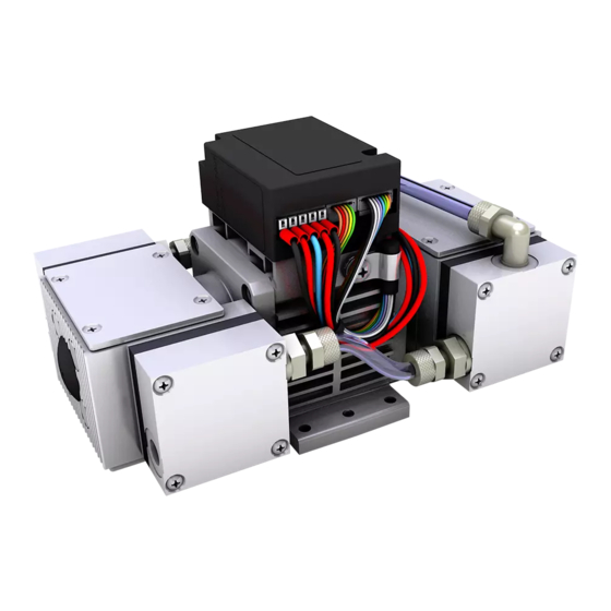
Motor Fig. 1: Assembly of N 84.3 ANE Assembly of N 84.3 ANDC Inlet (suction side) Pneumatic connection Outlet (pressure side) Motor Fig. 2: Assembly of N 84.3 ANDC Translation of original Operating and Installation Instructions, english, KNF 121256-121525 08/23... - Page 13 Assembly of N 84.4 ANDC and N 84.4 AN.29DC-B Inlet (suction side) Outlet (pressure side) Pneumatic connection Motor Fig. 4: Assembly of N 84.4 ANDC-B and N 84.4 AN.29DC-B Translation of original Operating and Installation Instructions, english, KNF 121256-121525 08/23...
- Page 14 (1). The diaphragm hermetically seals the work- ing chamber (3) from the pump drive (7). Translation of original Operating and Installation Instructions, english, KNF 121256-121525 08/23...
-
Page 15: Installation And Connection
Before installation, store the pump at the installation location to bring it up to ambient temperature. Dimensions Refer to Fig. 6 (N 84.3 ANE), Fig. 7 (N 84.3 ANDC), Fig. 8 (N 84.4 ANDC) or Fig. 9 (N 84.4 ANDC-B and N 84.4 AN.29DC-B) for the pump dimensions. - Page 16 Fig. 7: Attachment dimensions of N 84.3 ANDC (dimensional tolerances according to DIN ISO 2768-1, tolerance class V) Fig. 8: Attachment dimensions of N 84.4 ANDC (dimensional tolerances according to DIN ISO 2768-1, tolerance class V) Translation of original Operating and Installation Instructions, english, KNF 121256-121525 08/23...
- Page 17 Diaphragm Vacuum Pumps N 84 Installation and connection Fig. 9: Attachment dimensions of N 84.4 ANDC-B and N 84.4 AN.29DC-B (dimensional tolerances according to DIN ISO 2768-1, tolerance class V) *Connection (X) only for N 84.4AN.29DC-B Cooling air supply Only for N 84.3 ANE: ...
- Page 18 The voltage must not vary by more than + 10% and – 10% from that shown on the type-plate. 2. Connect the positive and negative terminals. Note the proper polarity: red connection cable: + black connection cable: - Translation of original Operating and Installation Instructions, english, KNF 121256-121525 08/23...
- Page 19 Control voltage may only be applied if the motor controller is supplied with operating voltage. Otherwise damages can occur on the motor controller. Translation of original Operating and Installation Instructions, english, KNF 121256-121525 08/23...
- Page 20 + Speisespannung rot / red AWG 18 + Supply voltage - Speisespannung schwarz / black / GND AWG 18 - Ground (0V) Tab. 8 : Connection plan motor electronics N84ANDC-B Translation of original Operating and Installation Instructions, english, KNF 121256-121525 08/23...
- Page 21 / 5V Power supply U Ausgangsspannung DC 5 ± 0.2 Control voltage range DC Max. Ausgangsstrom [mA] Max. current output Tab. 9 (part 1): Connection plan motor electronics N84AN.29DC-B Translation of original Operating and Installation Instructions, english, KNF 121256-121525 08/23...
- Page 22 1 ������������ ���� 0 … 100 Duty cycle ��������������������ℎ������������ Frequenz Ausgangsfrequenz* Output frequency* Tab. 9 (part 2): Connection plan motor electronics N84AN.29DC-B Fig. 12: Exposition Control with control voltage Translation of original Operating and Installation Instructions, english, KNF 121256-121525 08/23...
- Page 23 Diaphragm Vacuum Pumps N 84 Installation and connection Fig. 13: Exposition Control with Potentiometer Translation of original Operating and Installation Instructions, english, KNF 121256-121525 08/23...
- Page 24 Install the silencer in the pump’s outlet. 3. Connect suction and pressure lines. 4. Lay the suction and pressure lines at a downward angle to prevent condensate from running into the pump. Translation of original Operating and Installation Instructions, english, KNF 121256-121525 08/23...
-
Page 25: Operation
If a pump starts against pressure or vacuum, it may block. This activates the overload switch and the pump switches off. Translation of original Operating and Installation Instructions, english, KNF 121256-121525 08/23... - Page 26 The pumps may start against pressure or vacuum. This is also allowed if you experience a brief power interruption. Switching off the Restore the system to normal atmospheric pressure (release pump/removing from operation pneumatic pressure in pump). Translation of original Operating and Installation Instructions, english, KNF 121256-121525 08/23...
- Page 27 The following additional settings can be made at the factory upon request: Modify control voltage values Uc and Uc If the control voltage is less than Uc , the motor will be Translation of original Operating and Installation Instructions, english, KNF 121256-121525 08/23...
- Page 28 Remote ON/OFF is through an 8-pin controller connection (pin 6, see Fig. 11). To start the motor, Pin 6 must be bridged to the ground of the controller connection. Translation of original Operating and Installation Instructions, english, KNF 121256-121525 08/23...
- Page 29 Reed out of the following process parameters: Actual/Nominal motor speed Control limit of motor speed Operating current of the motor Temperature of the motor controller Fault status Software version number Translation of original Operating and Installation Instructions, english, KNF 121256-121525 08/23...
- Page 30 Nominal motor speed ns ; E Minimum possible motor nl ; E speed Maximum possible motor nh ; E speed Software version number V ; E Tab. 11: Reed commands Translation of original Operating and Installation Instructions, english, KNF 121256-121525 08/23...
- Page 31 See p. 21 for pin assignment of the motor controller’s commu- nication plug. Parameter Value Rx KNF MBLC Low: 0V…0.9V High: 4.2V…5.2V Tx KNF MBLC Low: 0V…0.6V High: 4.5V…5.2V Tab. 13 Translation of original Operating and Installation Instructions, english, KNF 121256-121525 08/23...
-
Page 32: Servicing
Solvent should be used for cleaning only if the head materials are not corroded (ensure compatibility of the material). If compressed air is available, blow out the parts. Translation of original Operating and Installation Instructions, english, KNF 121256-121525 08/23... - Page 33 Danger of burns from hot pump parts The pump head or motor may be hot even after the pump has been shut off. CAUTION Allow the pump to cool off after operation. Translation of original Operating and Installation Instructions, english, KNF 121256-121525 08/23...
- Page 34 On these models, which have no fan, where reference is made to turning or holding the cooling fan, the necessary operations must be carried out by turning or holding the counterweight (16). Translation of original Operating and Installation Instructions, english, KNF 121256-121525 08/23...
- Page 35 4. Check that the valve plates are not deformed by moving them gently sideways in their recesses. 5. Lay the sealing rings on the intermediate plate. Translation of original Operating and Installation Instructions, english, KNF 121256-121525 08/23...
- Page 36 Only for type range N 84.4: Repeat operations a) to e) for the both remaining pump heads. If you have any questions about servicing, call your KNF technical adviser (contact data: see www.knf.com). Translation of original Operating and Installation Instructions, english, KNF 121256-121525 08/23...
-
Page 37: Troubleshooting
Flush the pump (see Chapter 8.2.1). Install the pump at the highest point in the system. Diaphragm or valve plates are Replace diaphragm and valve plates (see Chapter 8.3). worn. Tab. 16 Translation of original Operating and Installation Instructions, english, KNF 121256-121525 08/23... - Page 38 Make sure that the shim rings have been replaced onto the have been replaced. diaphragm screw thread. Check head connection and hose connections for leaks. Tab. 17 Translation of original Operating and Installation Instructions, english, KNF 121256-121525 08/23...
- Page 39 2. Clean the pump (see Chapter 8.2.2). 3. Send the pump, together with completed Health and Safety Clearance and Decontamination Form, to KNF stating the na- ture of the transferred medium. Translation of original Operating and Installation Instructions, english, KNF 121256-121525 08/23...
-
Page 40: Spare Parts And Accessories
RS232 Level-Translator with SUB-D9 on request plug RS232 Level-Translator with Micro-USB on request plug Completely connectorized control cable on request (analog or digital controlling) Tab. 20 Translation of original Operating and Installation Instructions, english, KNF 121256-121525 08/23... -
Page 41: Returns
(see Chap- ter 8.2.1). Please contact your KNF sales partner if the pump cannot be flushed due to damage. 2. Remove the pump. - Page 44 KNF worldwide Find your local KNF partner on www.knf.com...
Need help?
Do you have a question about the N 84 and is the answer not in the manual?
Questions and answers