Table of Contents
Advertisement
Quick Links
Laboport
Operating
Instructions
Read and observe these
Operating Instructions!
KNF Neuberger UK Ltd
Ave 2, Station Lane Ind Est,
Witney, Oxfordshire,
OX28 4FA, UK
Tel: +44 (0)1993 778373
Fax: +44 (0)1993 775148
E-mail: info@knf.co.uk
www.knf.co.uk
®
Mini Laboratory Pumps
PM26285-811.18
Contents
1. About this document ............................................................... 3
2. Use ......................................................................................... 4
3. Safety ...................................................................................... 5
4. Technical Data ........................................................................ 7
5. Design and Function ............................................................... 9
6. Installation and connection .................................................... 10
7. Operation .............................................................................. 11
8. Servicing ............................................................................... 13
9. Troubleshooting .................................................................... 17
10. Spare parts and accessories ................................................. 19
11. Decontamination Declaration ................................................ 20
Page
Keep for future use!
Advertisement
Table of Contents

Subscribe to Our Youtube Channel
Related Manuals for KNF Laboport PM26285-811.18


Summary of Contents for KNF Laboport PM26285-811.18
-
Page 1: Table Of Contents
Contents Page 1. About this document ............... 3 2. Use ..................4 3. Safety ..................5 KNF Neuberger UK Ltd 4. Technical Data ................ 7 Ave 2, Station Lane Ind Est, 5. Design and Function ............... 9 Witney, Oxfordshire, 6. Installation and connection ............ 10 OX28 4FA, UK 7. -
Page 3: About This Document
About this document About this document 1.1. Using the Operating Instructions The Operating Instructions are part of the pump. Carefully study the Operating Instructions before using a pump. Always keep the Operating Instructions handy in the work area. Pass on the Operating Instructions to the next owner. Project pumps Customer-specific project pumps (pump models which begin with “PJ”... -
Page 4: Use
2.1. Proper use The pumps are exclusively intended for transferring gases and vapors. Owner's responsibility Operating parameters and Only install and operate the pumps under the operating parameters conditions and conditions described in chapter 4, Technical data. Make sure that the installation location is dry and the pump is protected against rain, splash, hose and drip water. -
Page 5: Safety
If necessary, consider any external sources of energy, such as radiation, that may add heat to the medium. In case of doubt, consult the KNF customer service. Environmental protection Store all replacement parts in a protected manner and dispose of them properly in accordance with the applicable environmental protection regulations. - Page 6 The pumps correspond to IEC 664: the overvoltage category II the pollution degree 2. Customer service and Only have repairs to the pump carried out by the KNF Customer repairs Service responsible. Only authorized personnel should open those parts of the housing that contain live electrical parts.
-
Page 7: Technical Data
Technical Data Technical Data All pumps are secured against overheating with thermal switches and are equipped with a mains fuse. Pump materials PM26285-811.18 Component Pump material* Pump head Diaphragm EPDM Valve plates/sealings Tab. 2 *according to DIN ISO 1629 and 1043.1 Refer to the type plate for the pump’s electrical configuration. - Page 8 Technical Data PM26285-811.18 Pneumatic performance Max. permissible operating pressure [bar g] Ultimate vacuum [mbar abs.] Delivery rate at atm. pressure 11.5 [l/min]* Pneumatic connections Hose connection [mm] ID 6 Ambient and media temperature Permissible + 5 °C to + 40 °C ambient temperature Permissible + 5 °C to + 40 °C...
-
Page 9: Design And Function
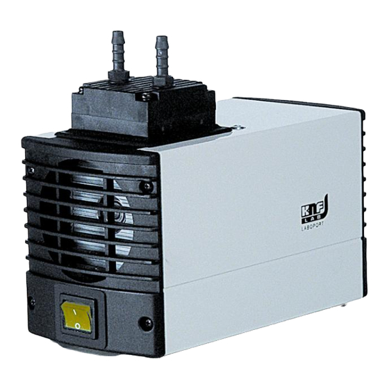
Technical Data 5. Des ign and F Function Design PM M26285-811. tlet (pressure e side) Inle et (suction sid mp head wer switch Fig. 3 Function Diaphragm P Pump tlet valve Inle et valve ansfer chambe aphragm centric nnecting rod mp drive Fig. -
Page 10: Installation And Connection
Installation and connection Installation and connection Only install and operate the pumps under the operating parameters and conditions described in chapter 4, Technical data. Observe the safety precautions (see chapter 3). 6.1. Installation Before installation, store the pump at the installation location to bring it up to room temperature. -
Page 11: Operation
For further information, contact your KNF technical adviser. Pump standstill With the pump at a standstill, open pressure and suction lines... - Page 12 Operation Automatic starting can cause personal injury and pump damage When the operation of the pump is interrupted by the thermal switch, the pump will restart automatically WARNING after cooling down. After triggering of the thermal protection or in the event of power failure, remove the pump’s mains plug from the socket so that the pump cannot start uncontrollably.
-
Page 13: Servicing
Servicing Servicing 8.1. Servicing Schedule Component Servicing interval Pump Regular inspection for external damage or leaks Filter (Accessory) Replace if it is dirty Diaphragm and valve Replace at the latest, when pump plates/sealings (valve output decreases plates) Tab. 5 8.2. Cleaning When cleaning, make sure that no liquids enter the inside of the housing. - Page 14 Servicing Changing Diaphragm and Valves Conditions Pump is switched off and mains plug is removed from the socket Pump is clean and free of hazardous materials Tubes removed from pump’s pneumatic inlet and outlet Spare parts/Tools Spare part/tool Service Set (according to chapter 10) Philips-head screwdriver No.
- Page 15 Servicing Change diaphragm 1. Using a small screwdriver, between the housing (1) and the outer edge of the diaphragm (8), carefully lever the edge of the diaphragm lightly upwards 2. Grip the diaphragm (8) on opposite sides, unscrew it about two turns (anti-clockwise).
- Page 16 Servicing Final steps 1. Reconnect suction and pressure line to the pump. 2. Reconnect the pump to the electricity supply. If you have any question about servicing call your KNF technical adviser (see last page for contact telephone number).
-
Page 17: Troubleshooting
Troubleshooting Troubleshooting Extreme danger from electrical shock! Disconnect the pump power supply before working on the pump. DANGER Make sure the pump is de-energized and secure. Check the pump (see Tab. 12 to 15). Pump produces no flow Cause Fault remedy No voltage in the power source Check room fuse and switch on if necessary. - Page 18 Fault cannot be rectified If you are unable to determine any of the specified causes, send the pump to KNF Customer Service (see first page for the ad- dress). 1. Flush the pump to free the pump head of dangerous or ag- gressive gases (see chapter 8.2.1).
-
Page 19: Spare Parts And Accessories
Spare parts and accessories 10. Spare parts and accessories 10.1. Spare parts A Service Set contains all spare parts needed for one complete service. For pump range PM26285-811.18: 1 diaphragm, 2 valve plates/sealings. Service Set for pump type: Order-No.: PM26285-811.18 044066 Tab. -
Page 20: Decontamination Declaration
Decontamination Declaration 11. Decontamination Declaration The condition for the repair of a pump by KNF is the certifica- tion of the customer on the transferred media and on the cleaning of the pump (decontamination declaration). Copy this page. KNF Neuberger UK Ltd Enter the pump model, the Serial No.
Need help?
Do you have a question about the Laboport PM26285-811.18 and is the answer not in the manual?
Questions and answers