Table of Contents
Advertisement
Quick Links
Advertisement
Table of Contents

Subscribe to Our Youtube Channel
Related Manuals for KNF N 0150


Summary of Contents for KNF N 0150
- Page 1 KNF 308918-308921 03/19 N 0150 TRANSLATION OF ORIGINAL OPERATING AND INSTALLATION INSTRUCTION ENGLISH DIAPHRAGM PUMP Note! Before operating the pump and the accessories, please read the operating and installation instructions and pay attention to the safety precautions!
-
Page 2: Table Of Contents
Index KNF Neuberger GmbH Alter Weg 3 1 About this document ............ 3 79112 Freiburg 2 Use ................... 4 Germany 3 Safety................ 5 Phone +49-(0)7664/5909-0 4 Technical data .............. 7 Fax. 07664/5909-99 5 Design and function ............ 10 Email: info@knf.de 6 Transport ................ -
Page 3: About This Document
An activity to be carried out is specified here (a step). 1. The first step of an activity to be carried out is specified here. This symbol indicates important information. Translation of Original operating and installation instruction, English, KNF 308918-308921 03/19... -
Page 4: Use
No operating pressure may be applied to the suction side of the pump. Pumps with capacitor motor are not intended for operation with a fre- quency converter. Translation of Original operating and installation instruction, English, KNF 308918-308921 03/19... -
Page 5: Safety
Environmental protection Store and dispose of all replacement parts in accordance with environmen- tal regulations. Observe the respective national and international regula- tions. This applies in particular to parts that are contaminated with toxic substances. Translation of Original operating and installation instruction, English, KNF 308918-308921 03/19... - Page 6 DIN EN 50581 § EN 60034-30-1 (only pumps with three-phase motor) Customer service and repairs The pumps are maintenance-free. KNF does, however, recommend peri- odically inspecting the pumps for noticeable changes to noises and vibra- tions. Only have repairs to the pumps performed by the responsible KNF Cus- tomer Service.
-
Page 7: Technical Data
Ultimate vacuum [mbar abs.] Flow rate at atm. pressure [l/ 130 ± 10% 100 ± 10% min]** Tab. 4 *Bar rel related to 1013 hPa **Liters in standard state (1013 hPa, 20°C) Translation of Original operating and installation instruction, English, KNF 308918-308921 03/19... - Page 8 Motor protection class See motor type plate Max. permissible mains See operating instructions for motor voltage fluctuations Tab. 8 *For further voltage and frequency variants, see type plate **See type plate Translation of Original operating and installation instruction, English, KNF 308918-308921 03/19...
- Page 9 A leak test can be used to determine whether the original gas tightness is again achieved. ***Values apply for helium leak test Translation of Original operating and installation instruction, English, KNF 308918-308921 03/19...
-
Page 10: Design And Function
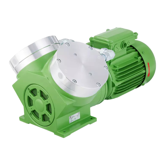
Fig. 1 Diaphragm pump N 0150 (three-phase motor) 1 Pneumatic pump outlet 2 Pneumatic pump inlet 3 Electrical terminal box 4 Motor 5 Motor fan cover Fig. 2 Diaphragm pump N 0150 (capacitor motor) Translation of Original operating and installation instruction, English, KNF 308918-308921 03/19... - Page 11 1 Pneumatic pump outlet 2 Union nut 3 Pneumatic head connec- tion 4 Motor 5 Motor fan cover 6 Electrical terminal box 7 Pneumatic pump inlet Fig. 4 Diaphragm pump N0150.3 (capacitor motor) Translation of Original operating and installation instruction, English, KNF 308918-308921 03/19...
- Page 12 (2). In the upwards stroke, the diaphragm presses the medium out of the pump head via the outlet valve (1). The transfer chamber (3) is hermetically separated from the pump drive (7) by the diaphragm. Translation of Original operating and installation instruction, English, KNF 308918-308921 03/19...
-
Page 13: Transport
- 10°C to + 60°C Permissible humidity (non-condens- 30% to 85% ing) Tab. 12 Prior to commissioning, make sure that the pump has reached the ambient temperature (4 Technical data). Translation of Original operating and installation instruction, English, KNF 308918-308921 03/19... - Page 14 3. Make certain that the lifting load cannot be transferred from the belt to the pump connection. 4. Lift the pump from the packaging with the help of lifting gear. 5. Lower the pump carefully at the installation location. Translation of Original operating and installation instruction, English, KNF 308918-308921 03/19...
-
Page 15: Installation And Connection
Before installing, store the pump at the installation location to allow it to reach the ambient temperature. Mounting dimensions à For mounting dimensions, see the following figures: Fig. 8 Mounting dimensions pump series N 0150.3 Translation of Original operating and installation instruction, English, KNF 308918-308921 03/19... - Page 16 Mount the pump at the highest point in the system to prevent conden- sate from collecting in the pump head. à Protect pump from dust. à Protect pump from vibration and impact. Translation of Original operating and installation instruction, English, KNF 308918-308921 03/19...
- Page 17 Fasten the connection cables so that – the cables do not come into contact with movable or hot parts. – the cables cannot be worn or damaged on sharp corners or edges Translation of Original operating and installation instruction, English, KNF 308918-308921 03/19...
- Page 18 In this way it is possible to prevent the transfer of possible pump vibrations and noises to the system. Translation of Original operating and installation instruction, English, KNF 308918-308921 03/19...
- Page 19 Water cooling (see 11.2 Accessories) can increase the service life of the diaphragm, particularly with high pressures or high ambient temperature. Recommended parameters Parameter Value Water temperature + 5°C to + 30°C Water flow rate [l/min] Tab. 13 Translation of Original operating and installation instruction, English, KNF 308918-308921 03/19...
- Page 20 The base plate is shown as an additional accessory on the following dimensional drawings. Fig. 10 Mounting dimensions pump series N 0150.3 Fig. 11 Mounting dimensions pump series N 0150 à Operate the water connection up to max. 1.0 bar gauge. Translation of Original operating and installation instruction, English, KNF 308918-308921 03/19...
- Page 21 Diaphragm Pump N 0150 Installation and connection à Safely drain water discharge. à Flow in both directions is permissible. Translation of Original operating and installation instruction, English, KNF 308918-308921 03/19...
-
Page 22: Operation
The pumps are built-in devices. Before they are commissioned, it must be ensured that the machines or systems into which the pumps are in- stalled comply with the relevant provisions. Translation of Original operating and installation instruction, English, KNF 308918-308921 03/19... - Page 23 Further informa- tion is available from the KNF technical adviser (for contact data, see www.knf.de). Risk of dangerous gas mixtures during pump op-...
- Page 24 Recommissioning Before recommissioning, observe the applicable standards, guidelines, regulations and technical standards at the electrical connection. à Inspecting the pump Inspect the pump periodically for external damage or leakage. Translation of Original operating and installation instruction, English, KNF 308918-308921 03/19...
-
Page 25: Servicing
During cleaning work, ensure that no fluids enter the interior of the housing. à Solvents should only be used during cleaning if head materials are not affected (ensure resistance of the material). Translation of Original operating and installation instruction, English, KNF 308918-308921 03/19... - Page 26 1 (per pump head) side Screw (13) 4 (per pump head) Tab. 15 * According to spare parts list, Chapter 11.1 Spare parts ** According to Individual parts of the pump head Translation of Original operating and installation instruction, English, KNF 308918-308921 03/19...
- Page 27 4 mm, length approx. 160 mm (available as wrench for retainer plate as KNF accessory, see 11.2 Accessories). Felt-tip pen Hot-air blower Adhesive (Delo ML5249) or comparable product Tab. 16 *According to accessory list, Chapter 11.2 Accessories Translation of Original operating and installation instruction, English, KNF 308918-308921 03/19...
- Page 28 4. Loosen the six hexagon socket head cap screws (12) as well as the two screws (16); remove head plate (1) and intermediate plate (3). 5. For two-headed pumps: Perform steps 3 and 4 for second pump head. Translation of Original operating and installation instruction, English, KNF 308918-308921 03/19...
- Page 29 9. Only .13: Insert new O-ring (10) in housing (5). 10. Only .13: Insert new O-ring (8) in conrod plate (9). Translation of Original operating and installation instruction, English, KNF 308918-308921 03/19...
- Page 30 9. For two-headed pumps: Remount the pneumatic connection between the pump heads. In doing so, retighten the union nuts to the original position (as marked during disassembly, see Fig. 13). Translation of Original operating and installation instruction, English, KNF 308918-308921 03/19...
-
Page 31: Troubleshooting
Thermal switch or triggering device Disconnect pump from electrical mains. for PTC thermistor sensor of the à Allow pump to cool. motor has tripped. à Determine cause of the overheating and rectify. Tab. 17 Translation of Original operating and installation instruction, English, KNF 308918-308921 03/19... - Page 32 3. Send the pump together with completed Health and Safety Clearance and Decontamination Form (see Chapter Health and safety clearance and decontamination form) to KNF, stating the nature of the transferred medium. Translation of Original operating and installation instruction, English, KNF 308918-308921 03/19...
-
Page 33: Spare Parts And Accessories
Tab. 20 11.2 Accessories Accessories Order number Water cooling connection: N 0150S_ 305998 N0150.3S_ 306765 Suction filter G1/4 316662 Base plate with rubber-bonded 304463 metal: N 0150 N 0150.3 Tab. 21 Translation of Original operating and installation instruction, English, KNF 308918-308921 03/19... -
Page 34: Returns
Customers can conveniently provide all details that KNF requires for the processing of the return using an online form in the "Product/Service" area at www.knf.de. All steps necessary for the return to KNF are also provided there. Translation of Original operating and installation instruction, English, KNF 308918-308921 03/19... -
Page 35: Appendix
Diaphragm Pump N 0150 Appendix 13 Appendix See also § Betriebsanleitung Drehstrommotormotor DE-EN.pdf § CE-Erklärung Drehstrommotor DE-EN.pdf § Betriebsanleitung Kondensatormotor DE-EN.pdf § CE-Erklärung Kondensatormotor DE-EN.pdf Translation of Original operating and installation instruction, English, KNF 308918-308921 03/19... - Page 36 Deutsch / English Betriebsanleitung für Drehstrommotoren (IE2 + IE3 nach IEC 60034-30) Operating Instructions for three-phase-motors (IE2 + IE3 according to IEC 60034-30) Baugröße / HEF IE2 80 L/.. - HEF IE2 355 L/.. Frame size HEF IE3 80 L/.. - HEF IE3 355 L/.. Ausgabe / Edition 07.15 Art.-Nr.
- Page 37 Deutsch Die in dieser Betriebsanleitung enthal- Vor Inbetriebnahme des Motors, nach längerer Lagerungsdauer oder Stillstandzeit (größer 6 Monate), muß der Isolationswiderstand der tenen Sicherheitshinweise sind unbe- Wicklung ermittelt werden. Wicklung mittels Isolationswertmeßgerät dingt zu beachten! (max. Gleichspannung 500 V) gegen Masse prüfen. Sonderausführungen und Bauvarianten können in technischen Ist der Mindest-Isolationswiderstand bei einer Wicklungstemperatur Details von der Grundtype abweichen.
- Page 38 Deutsch / English 3.5 Elektrischer Anschluß Instandhaltung elektrische Anschluß darf durch einen Fachmann Alle Arbeiten am Motor nur im abge- entsprechend den geltenden Sicherheitsvorschriften vorgenommen schalteten, gegen Wiedereinschalten werden. gesicherten Zustand durchführen! Neben den Hauptstromkreisen auch auf Netzspannung und -frequenz müssen mit den Daten auf dem eventuell vorhandene Zusatz-oder Hilfstromkreise, insbesondere Leistungsschild übereinstimmen.
- Page 39 Deutsch / English Ca. 50% des freien Raumes im Lager sowie der Fetträume im Lager- English schild bzw. Lagerdeckel mit Fett der zugelassenen Qualitäten füllen. The safety instructions in this operating Dichtungselemente (z.B. Wellendichtringe) müssen vor dem Zusam- manual are to be observed at all times. menbau auf Funktion sowie Beschädigung überprüft und bei nicht mehr ausreichender Wirksamkeit erneuert werden.
- Page 40 English 2.3 To check the insulation resistance 3.5 Electrical connection The electrical connection may only be performed by a specialist in When measuring insulation accordance with current safety regulations. resistance and immediately afterwards terminals carrying The mains voltage and frequency must comply with the data on the dangerous voltages and must not be touched.
- Page 41 English Fill approx. 50% of the free space in the bearing and the grease Maintenance chambers in the bearing plate and bearing cover with grease of approved quality. Before completing any work on the motor, ensure that it has been switched The sealing elements (eg.
- Page 42 Deutsch / English Anhang / Appendix Bild 1: Schmierstoffe Fig. 1: Lubricants Betriebsbedingungen Wärmeklasse Wälzlagerfett / Einsatzbereich Operating conditions Temperature class Bearing grease / Application / -30 C bis +140 C Normal Baugrößen 80 – 112: Lithiumseifenfett / -20 C bis +140 C Baugrößen 132 –...
- Page 43 Deutsch / English Bild 4: Ersatzteile Fig. 4: Spare parts Teile.-Nr. Bezeichnung Description Part No. Gehäuse (IMB3) Casing (IMB3) Gehäuse ohne Füße (IMB5 / IMB14) Casing without feet (IMB5/IMB14) Motorfüße Motor feet Statorpaket mit Wicklung Stator cove with winding Rotor mit Welle Rotor with shaft 4.0.
- Page 44 Deutsch / English...
- Page 46 Deutsch / English Betriebsanleitung für Einphasenmotoren Operating Instructions for single-phase motors Baugrößen (Bg.) 56 ..112 EAZR Frame size Ausgabe / Edition 07.15 Art.-Nr. / Art. No.: 187278 Ident.-Nr. / Ident No.: B.51.820.003 Alle Rechte vorbehalten! / All rigths reserved. ...
- Page 47 Deutsch Die in dieser Betriebsanleitung enthal- 2.2 Lagerung tenen Sicherheitshinweise sind unbe- Der Lagerort sollte nach Möglichkeit trocken, sauber, temperatur- dingt zu beachten! konstant und erschütterungsfrei sein. Sonderausführungen und Bauvarianten können in technischen Details von der Grundtype abweichen. Bei eventuell auftreten- Damit der Schmierfilm in der Motorlagerung und den Dichtungs- den Unklarheiten wird dringend empfohlen sich mit der EMOD systemen nicht abreißt, sollte bei längerer Einlagerungszeit die...
- Page 48 English 3.7.2 Ausrichten bei Kupplungsbetrieb 3.4 Auswuchtung Bei Kupplungsbetrieb sind die Wellen axial und radial gegeneinander Wird ein Motor ohne Antriebselement in auszurichten. Das Einstellen der Luft zwischen den Kupplungshälften Betrieb genommen, so ist die Paßfeder ist nach den Angaben der Kupplungshersteller vorzunehmen. gegen herausschleudern zu sichern.
- Page 49 English 3 Jahren nicht erreicht werden sollte vorzeitig nachgeschmiert Ersatzteile werden. Nachschmieren nur bei drehendem Läufer, damit sich das neue Fett im Lager verteilt! Bei Ersatzteilbestellungen bitte neben der genauen Teilebezeich- nung unbedingt Motortype und Motornummer (Daten sind dem Schmierstoffe (siehe Bild 2) Leistungsschild zu entnehmen) angeben.
- Page 50 English English 2.2 Storage The storage site should, if possible, by dry, clean, kept at a constant The safety instructions in this operating temperature and not subject to shocks. manual are to be observed at all times. To protect the bearings and the lubricating system, the motor shaft Special versions and variants may differ has to be turned around from some rotations from time to time.
- Page 51 English Only use couplings which are elastic to central offset, angled, 3.4 Balancing longitudinal and rotary motion. Rigid couplings are not allowed and If a motor is commissioned without a may only be used in exceptional cases by agreement with the drive element, the fitted spring is to be manufacturer.
- Page 52 English Lubricants (see Figure 2). Do not mix different types of grease. 4.3 Repair work Spare parts lists and normal drawings do not contain any detailed information on the type and dimensions of the components. Therefore, when dismantling the motors, mark the components so that you know which part belongs where to facilitate re-assembly.
- Page 53 Deutsch / English Bild 1: Einscheiben-Federkraftbremse Fig. 1: Single-disc springloaded brake Bremsmoment / Braking torque (Nm) Luftspalt X / Air gap X (mm) Bild 2: Schmierstoffe Fig. 2: Lubricants Betriebsbedingungen Wärmeklasse Wälzlagerfett / Einsatzbereich Operating conditions Temperature class Bearing grease / Application / -30 C bis +140 C Normal Baugrößen 56 –...
- Page 54 Deutsch / English Bild 4: Anschlußschaltbild Fig. 2: Connection diagram...
- Page 56 KNF worldwide Find your local KNF partner on: www.knf.com...
Need help?
Do you have a question about the N 0150 and is the answer not in the manual?
Questions and answers