Table of Contents
Advertisement
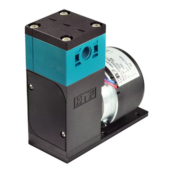
DIAPHRAGM LIQUID PUMP
NF 100, NF 1.100, NFB 100
NF 100 KP .51 .27 DC 12V
.51 / - [Ch. 2]
KP / KT / TT / FT [Ch. 4]
100 / 1.100
NF / UNF / JNF / NFB / UNFB
- / PMLxxxx / PLxxxx [Ch. 1]
Operating and
Installation
Instructions
Read and observe these
Operating and Installation
Instructions!
An additional letter prefixing
the NF model code is a coun-
try-specific designation, with
no technical relevance.
KNF Flodos AG
Wassermatte 2
6210 Sursee, Switzerland
Tel +41 (0)41 925 00 25
Fax +41 (0)41 925 00 35
www.knf.com
info.flodos@knf.com
KNF Flodos BA_NF100_EN_10_067676.docx
Translation of original Operating and Installation Instructions
Supply voltage [Ch. 4]
AA / DC / DCB / DCB-4
.27 / - [Ch. 5]
Contents
1. About this document ................................................................. 2
2. Use ........................................................................................... 3
3. Safety ....................................................................................... 5
4. Technical data .......................................................................... 7
5. Assembly and function ........................................................... 10
6. Installation and connection ..................................................... 12
7. Operation ................................................................................ 20
8. Servicing ................................................................................. 25
9. Troubleshooting ...................................................................... 29
10. Spare parts and accessories .................................................. 31
11. Return of the pump ................................................................. 32
Page
Keep for future reference!
Advertisement
Table of Contents

Related Manuals for KNF NF 100


Summary of Contents for KNF NF 100
-
Page 1: Table Of Contents
DIAPHRAGM LIQUID PUMP NF 100, NF 1.100, NFB 100 NF 100 KP .51 .27 DC 12V Supply voltage [Ch. 4] AA / DC / DCB / DCB-4 .27 / - [Ch. 5] .51 / - [Ch. 2] KP / KT / TT / FT [Ch. 4] 100 / 1.100... -
Page 2: About This Document
Diaphragm liquid pump NF 100 About this document About this document 1.1. Use of the Operating and Installation Instruc- tions The Operating and Installation Instructions are part of the pump. Forward the Operating and Installation Instructions to any subsequent owners of the pump. -
Page 3: Use
Diaphragm liquid pump NF 100 2.1. Intended use The pumps are intended for transferring and metering liquids. Owner's responsibility Operating parameters and Only install and operate the pumps under the operating parameters conditions and conditions described in Chapter 4, Technical data. - Page 4 The pumps must not be operated in an explosive atmosphere. DANGER For special modifications outside the standard technical specifica- tions, please contact your KNF technical adviser (see last page for telephone number). KNF Flodos BA_NF100_EN_10_067676.docx Translation of original Operating and Installation Instructions...
-
Page 5: Safety
Diaphragm liquid pump NF 100 Safety Safety Observe the safety precautions in Chapters 6. Installation and connection and 7. Operation. The pumps are built according to the generally recognised rules of technology and in accordance with the pertinent occupational safety and accident prevention regulations. Nevertheless, dangers may occur during their use which may lead to injuries to the user or others, or to damage to the pump or other property. - Page 6 In order to comply with the specified standards, the pump must be connected as described in Chapter 6.2. Customer service and All repairs to the pump(s) must be carried out by the relevant KNF repairs Customer Service team. Only use genuine parts from KNF for servicing work.
-
Page 7: Technical Data
Diaphragm liquid pump NF 100 Technical data Technical data Pump materials The pump type KP / KP.51 stands for: Assembly Material Pump head* Valve plate EPDM Diaphragm PTFE-coated Resonating diaphragm PTFE Diaphragm. 27 EPDM Tab. 2 according to DIN ISO 1629 and 1043.1... - Page 8 1), 2) 2 x 1.3 Flow rate NFB 100 [l/min] 1), 2) Max. permissible pressure NF 100, NFB 100 [bar g] Max. permissible pressure NF 1.100 [bar g] Suction head [mWG] Tab. 6 Measured with water at 20 °C / at atmospheric pressure Flow rates may vary from the values shown, depending on fluid viscosi- ty, pump head material and the hoses / hose connectors used.
- Page 9 Diaphragm liquid pump NF 100 Technical data Specifications NF 1.100 AA Motor voltage 230V / 50Hz Power consumption [W] Max. I load [A] 0.36 Max. permissible current 0.50 consumption [A] Protection class [-] IP 54 Weight 2450 Tab. 11 Specifications NF 1.100 DC...
-
Page 10: Assembly And Function
This pump type represents this product in its simplest form and transfers media at the fixed flow rate. NF 100.27 version (fixed flow rate with overpressure limiting) If the diaphragm liquid pump is operating against a closed system, the delivery pressure quickly exceeds the maximum permissible value. - Page 11 Diaphragm liquid pump NF 100 Assembly and function NFB 100 version (double-headed pump with fixed flow rate) This pump type has two NF100 pump heads that can be operated individually or together (see Chapter 6.3.2). KNF Flodos BA_NF100_EN_10_067676.docx Translation of original Operating and Installation Instructions...
-
Page 12: Installation And Connection
Mounting dimensions Mounting dimensions (see Fig. 3 to 9) Fig. 3: Mounting dimensions NF 100 AA Fig. 4: Mounting dimensions NF 1.100 AA KNF Flodos BA_NF100_EN_10_067676.docx Translation of original Operating and Installation Instructions... - Page 13 Diaphragm liquid pump NF 100 Installation and connection Fig. 5: Mounting dimensions NF 100 DC Fig. 6: Mounting dimensions NF 1.100 DC Fig. 7: Mounting dimensions NF 100 DCB KNF Flodos BA_NF100_EN_10_067676.docx Translation of original Operating and Installation Instructions...
- Page 14 Diaphragm liquid pump NF 100 Installation and connection Fig. 8: Mounting dimensions NF 1.100 DCB Fig. 9: Mounting dimensions NFB 100 DCB-4 Cooling air supply For pumps with fan: When installing the pump, make sure that the motor’s fan can draw in an adequate amount of cooling air.
- Page 15 Diaphragm liquid pump NF 100 Installation and connection KNF recommends mechanically decoupling the pump from the Decoupling piping system. This can be achieved with flexible hoses or pipes, for example. This prevents any oscillations of the pump being transferred to the system.
- Page 16 Diaphragm liquid pump NF 100 Installation and connection 6.2. Electrical connection For pumps with alternating current motors: Risk of electric shock, danger of death Only have the pump connected by an authorized specialist. Only have the pump connected when the power DANGER supply is disconnected.
- Page 17 Diaphragm liquid pump NF 100 Installation and connection Supplemental circuit In order to ensure that emissions comply with the EN 55011 or EN for brushless DCB motors 55022 emission standards, this pump type with a brushless DC motor DCB must be fitted with a supplemental circuit. The supple- mental circuit must be installed as close as possible to the motor.
- Page 18 Diaphragm liquid pump NF 100 Installation and connection 6.3. Hydraulic connection Connected Only connect components to the pump that are designed to components handle the hydraulic data of the pump (see Chapter 4, Technical data). Hoses Only use hoses that are suitable for the maximum permissible operating pressure of the pump (see Chapter 4).
- Page 19 As little constriction as possible should be caused when using for NFB versions connecting components. As a guide: min. inner diameter 5.5 Contact your KNF technical advisor if you have any questions (see last page for telephone number). Fig. 13: NFB 100 hose configuration for low pulsation...
-
Page 20: Operation
For further information, contact your KNF technical adviser (for telephone number, see last page). Risk of burns when transferring hot media ... - Page 21 Diaphragm liquid pump NF 100 Operation Risk of physical injury and damage to the pump due to automatic start If the pump overheats and pump operation is stopped by the thermal switch / electronics, the WARNING pumps will restart automatically as soon as they have had time to cool down.
- Page 22 Short start and stop cycles may adversely affect the service life of the brushed motors. If the pump is operated with short cycles in your application, please contact a KNF technical adviser for further information (for telephone number, see last page). Switching on the pump ...
- Page 23 Diaphragm liquid pump NF 100 Operation Flow rate NF 100 Fig. 15: Flow rate of pump NF 100 AA / DC / DCB Flow rate NF 1.100 Fig. 16: Flow rate of pump NF 1.100 DC Fig. 17: Flow rate of pump NF 1.100 AA / DCB KNF Flodos BA_NF100_EN_10_067676.docx...
- Page 24 Diaphragm liquid pump NF 100 Operation Flow rate NFB 100 (per pump head) Fig. 18: Flow rate of pump NFB 100 DCB-4 (per pump head) 1.40 0 mWG 10 mWG 1.20 1.00 0.80 0.60 0.40 0.20 Control voltage [VDC] Fig. 19: Flow rate of pump NFB 100 DCB-4 (per pump head), depending on control voltage KNF Flodos BA_NF100_EN_10_067676.docx...
-
Page 25: Servicing
Flush the pump with a neutral liquid and pump empty. 8.2.1. Flushing the pump When transferring aggressive media, KNF recommends flush- ing the pump with air (or an inert gas if necessary for safety reasons) under atmospheric conditions for a few minutes be- fore switching off in order to extend the service life of the dia- phragm. - Page 26 The method of assembly which follows will differ according to the pump type used. For this reason, please proceed with the section (NF 100 and NFB 100 versions or NF 100.27 ver- sion) that corresponds to the pump type you are using.
- Page 27 Diaphragm liquid pump NF 100 Servicing NF 100.27 version Insert resonating diaphragm.27 (15) in the connecting plate (5). Place the diaphragm.27 (14) centrally on the resonating dia- phragm.27 (15). Place the compression spring.27 (13) over the thread of the diaphragm.27 (14).
- Page 28 Diaphragm liquid pump NF 100 Servicing 8.3. Adjusting the overflow Test set-up/instrumentation as shown in the diagram. Test set-up for overflow Make sure that the container (a), pump (b), pressure gauge (c) and valve (d) are as level as possible (+/- 15 cm) Fig.
-
Page 29: Troubleshooting
Diaphragm liquid pump NF 100 Troubleshooting Troubleshooting For pumps with alternating current motors: Risk of electric shock, danger of death Disconnect the pump from the power supply before working on the pump. DANGER Make sure that the pump is de-energised. - Page 30 Fault cannot be rectified If you are unable to identify any of the above causes, please send the pump to KNF customer service (see address on last page). Flush the pump to clear the pump head of any hazardous or aggressive liquids (see Chapter 8.2.1).
-
Page 31: Spare Parts And Accessories
152631 Spare parts kit KP.27 067529 Spare parts kit KT.27 / TT.27 067530 Tab. 22 For KP.51 version, contact your KNF technical advisor. Accessories Accessories Order No. Screw-in nipple with seal EPDM R1/8" 168554 Screw-in nipple with seal EPDM NPT1/8"... -
Page 32: 11. Return Of The Pump
Return of the pump 11. Return of the pump KNF undertakes to repair the pump only under the condition that the customer provides a certificate of the pumped medium and cleaning of the pump. For this purpose, please follow the instructions on www.knf.com/repairs. - Page 33 Diaphragm liquid pump NF 100 Your Notes KNF Flodos BA_NF100_EN_10_067676.docx Translation of original Operating and Installation Instructions...
- Page 34 KNF worldwide Please find your local KNF partners at: wwwknf.com...
Need help?
Do you have a question about the NF 100 and is the answer not in the manual?
Questions and answers