SI Zero-G Installation Instructions Manual
Flush
Hide thumbs
Also See for Zero-G:
- Owner's manual (20 pages) ,
- Installation instructions manual (54 pages) ,
- Installation instructions manual (40 pages)
Table of Contents
Advertisement
Quick Links
Zero-G (Flush)
Installation Instructions
Failure to comply with the following steps will result in a void of the manufacturer's warranty. The dealer/
installer will be responsible for all costs associated with failure to comply, including replacement parts, and/
or additional on-site visits needed for repair work.
• Do not use a knife to cut foam/wrapping, you may cut cables.
• Due to the complexity of Zero-G, please scan the QR code to review the installation video before
proceeding:
• A minimum of 12" of drop must be met to ensure no mechanical failures.
• Please use the supplied data cable & wall switch for initial setup before introducing 3rd party
control systems.
• Before operating, please inspect helix & wing cable pulleys didn't lose tension during transit.
• Please contact SI support at (512) 832-6939 w/ any install related questions prior to installation
or scan the QR code to get more details:
• Leveling the Zero G Case and Wing/Lower Tube Assembly: These pieces MUST be level and
parallel within 1/16th of an inch. Failure to accurately level these two pieces can cause the
screen cables to become unstable and fray over time.
INSTALLERS: PLEASE LEAVE THIS MANUAL WITH THE OWNER.
ZERO-G DISCLAIMER
Installation video
for external Zero G
Support page
QR code
Advertisement
Table of Contents

Subscribe to Our Youtube Channel
Related Manuals for SI Zero-G


Summary of Contents for SI Zero-G
- Page 1 • Do not use a knife to cut foam/wrapping, you may cut cables. • Due to the complexity of Zero-G, please scan the QR code to review the installation video before proceeding: •...
- Page 2 Scan the QR code to view the SI warranty for this product. Please use this QR Code to access the updated installation instructions and related documents. Technical Support: 512.832.6939 screeninnovations.com Hours of Support: 7:30am – 5pm CST screensupport@screeninnovations.com...
-
Page 3: Table Of Contents
TABLE OF CONTENTS Before Proceeding Product Overview Parts In The Box Opening The Box Pre-Mounting Power Consideration Installation Type 9 - 16 Suspended Ceiling 10 - 14 L-Brackets 15 - 16 Power & Control 17 - 22 Screen Inspection 23 - 24 Controls Wall Switch General Operation Setting The Drop For Viewing Height... -
Page 4: Before Proceeding
Do not pull on the sides, crease, or fold the screen. The screen material is very delicate. • Care in mounting and correct operation will result in long and satisfactory service from the SI screen. • The screen should be level when installed. Always use a carpenter’s level. -
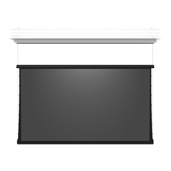
Page 5: Product Overview
PRODUCT OVERVIEW It is important to familiarize yourself with the product and its parts prior to installation. Please refer to the diagram and definitions below. Case Drop Dyneema™ Wing Viewing Area Tab Tension Lower Tube 1. Case - The case is the enclosure of the screen that houses the upper tube assembly, doors, controls, and the lower tube assembly when the screen is retracted. -
Page 6: Parts In The Box
PARTS IN THE BOX Installation requires three or more people. The product weighs up to 225 lbs. Please use safe lifting and rigging techniques. Flush Mount Case Cassette Doors Lift Bars Mounting Parts End Cap Trim L-Brackets* Suspended Ceiling Spade Brackets* Connector 16 x - 24 x... -
Page 7: Opening The Box
OPENING THE BOX Do not remove the foam(A) or packaging inside the cassette at this time. Cut the straps to open the box, then remove the trim pieces, doors assemblies, and mounting brackets and set all of them out of the way of the installation area. -
Page 8: Pre-Mounting Power Consideration
PRE-MOUNTING POWER CONSIDERATION Before mounting the screen, consider how power and data will be routed to the screen. Depending on site conditions, it may be necessary to run these wired or pull a cord before case installation. With the breaker Off, run the power and control cables through their appropriate case penitrations. Pass the control and power cables through the appropriate openings in the case. -
Page 9: Installation Type
INSTALLATION TYPE Suspended Ceiling L Bracket Check Pg. 10 for Installation Instructions Check Pg. 15 for Installation Instructions... -
Page 10: Suspended Ceiling
SUSPENDED CEILING Ceiling Pocket Preparation Measure full length of the case (F). Blocking required. The ceiling or wall used for fixture installation must be able to support 300 lbs or more. Failure to properly secure the screen may result in injury and/or damage. Cut a hole in the ceiling using the Z and W values from the formula above. - Page 11 SUSPENDED CEILING Pre-Installation steps Secure 4 threaded rods to structural supports above the installation location as shown. Failure to properly level the mounting brackets will create issues with the screen over time, damaging the screen material. Stuctural Member 4” - 20” 4”...
- Page 12 SUSPENDED CEILING Case Installation Lift the case up to the threaded rods and secure it in place with the installer provided nuts and washers. Installation requires three or more people. The product weighs up to 225 lbs. Please use safe lifting and rigging techniques. 1/2 “...
- Page 13 SUSPENDED CEILING Flush Case to Ceiling Install the door trim test piece into the case to use as a reference for the following step (2).
- Page 14 SUSPENDED CEILING Flush Case to Ceiling Raise the case up until the door test trim piece is flush with the ceiling. Repeat this at the front and back of all mounting brackets. Level the case to within 1/8” over 10’ using the case length (F); as well as 1/2”over 1’ using the depth (W) of the pocket.
-
Page 15: L-Brackets
L-BRACKETS Installation Install the brackets so that they will be 2” - 18” from either sides of the cassette. The ideal range is 2” - 4”. Level the brackets to within 1/8” over 10’ using the case length (F); as well as 1/2”over 1’ using the depth (W) of the pocket. - Page 16 L-BRACKETS Case Installation Installation requires three or more people. The product weighs up to 225 lbs. Please use safe lifting and rigging techniques. Make sure bracket hook screws (see Fig. A) are backed out all the way down, before putting the screen in place.
-
Page 17: Power & Control
POWER & CONTROL Open the tray. Carefully unscrew and pull down the control center ensuring none of the cables or motherboard become damaged. If you feel resistance do not yank. Do Not access The Control Board unless the Circuit Breaker is off or power is disconnected. - Page 18 POWER & CONTROLS All RJ 45 Ports act the same, and can be used for wall switch, IR Eye, or 3rd Party Control. Low Voltage Trigger 3X RJ45 Ports Port External RJ 45 Securely connect power to the terminal block on the control center. It is recommended to crimp the provided spade connectors to the incoming power wires.
- Page 19 POWER & CONTROL Low Voltage Trigger (Optional) Some projectors output a low-voltage trigger that will deploy your screen when the projector is powered on. Installer must supply conductor wire in the length and guage needed. Two 3.5mm jacks are included and should be connected to the installer provided cable following the diagram below.
- Page 20 POWER & CONTROL IR Remote (Optional) IR Remote Use • If the IR remote is held down continuously as the screen is moving there is a chance that the screen can stop in-between limits. If this happens simply send another IR signal in the direction it was going to continue its movement.
- Page 21 POWER & CONTROLS 3rd Party Control Dry Contact Below is the pin out for Dry Contact, Board damage is possible if wired incorrectly. Momentary RJ45 Male Plug Pin 1 Contact UP UP - Pin 3 GROUND - Pin 4 DOWN - Pin 6 Momentary Contact DOWN NOT USED - Pin 5...
- Page 22 POWER & CONTROLS To close the Control Panel, Carefully push up the control center back into the tray ensuring the cables or motherboard are not damaged. Tighten panel fastening screws. Do not force the control panel. If it does not close easily, reopen the panel and look for wires or other obstructions and then attempt to close it again.
-
Page 23: Screen Inspection
SCREEN INSPECTION Carefully remove the “Remove Before Opening” stickers and inspect the helix and pulleys, verifying the dynemma is correctly orientated, refer to the images on next 2 pages. The foam should remain in place as it will lower with the screen. - Page 24 SCREEN INSPECTION Make sure that the cable is wrapped correctly on both helixes as shown, seen from below. If the cable becomes loose, make sure the it is still set correctly on all pulleys as shown. Follow the numbers to indicate where the cables are to be routed if they come off of the pulley grooves. For Double Pulley (Back view)
-
Page 25: Controls
Adjusting the upper limit is set at the the factory and should not be adjusted. If motor is going in the wrong direction, view the “Reversing Polarity on Zero-G” on our support page, scan this QR code:... -
Page 26: Setting The Drop For Viewing Height
SETTING THE DROP FOR VIEWING HEIGHT This step will set the height at which screen will start to deploy, and should be considered upper portion of the viewing height. Hold the down button on the wall switch to drop the screen and release at the desired drop. - Page 27 SETTING THE DROP FOR VIEWING HEIGHT Removal of the Packaging Dispose of all packaging. Carefully remove protective tube and foam wrapped around screen inside protective tube making sure to not damage the screen.
- Page 28 SETTING THE DROP FOR VIEWING HEIGHT Removal of the Packaging Carefully cut the rubber banding or zip ties using flush cutters or similar precision wire cutters/ sscissors.
- Page 29 SETTING THE DROP FOR VIEWING HEIGHT Loosen the thumb screw connected to the wing cable spool. For Double Pulley If the cable becomes loose, make sure the it is still set correctly on all pulleys as shown. Follow the numbers to indicate where the cables are to be routed if they come off of the pulley grooves. Back view...
- Page 30 SETTING THE DROP FOR VIEWING HEIGHT Adjusting the wing to level Measure from the case to the middle side of the wing on both sides and check to make sure they are equal to within 1/16’’. We recommend raising the side that is lower, loosen the thumb screw on the side that needs to be adjusted to level out the wing.
- Page 31 SETTING THE DROP FOR VIEWING HEIGHT Both the wing cables should have tension on them. Tighten the thumb screw firmly to secure the wing drop setting. Perform Steps 2 through 3 on both ends of the screen. The wing pulleys should not engage with the stopping plate if you need extended drop.
-
Page 32: Setting The Lower Limit
SETTING THE LOWER LIMIT Make sure the Slide switch on the back of the Wall switch is in the lower position. Hold the DOWN button on the Wall switch until the viewing area is fully visible with no more than 3” of backer showing at the bottom. NORMAL OPERATION SET LOWER LIMIT SET UPPER LIMIT... -
Page 33: Installing Side Trim Left Trim
INSTALLING SIDE TRIM Left Trim Plug the IR eye located in the motor side end trim to the RJ45 port on the bottom of the control center. Attach the end trim to the case with 2 thumb screws. - Page 34 INSTALLING SIDE TRIM Right Trim Attach the idler side trim piece to the stand offs on the right side of the case, using 3 thumb screws.
-
Page 35: Installing Doors
INSTALLING DOORS Installation requires three or more people. Doors and trim do not maintain rigidity untill installed and require multiple points of contact to properly install. Drop the screen and Stop at the point where the screen starts to deploy. Lift the door and trim assemblies up, butt up against the right end trim and then hook into the case as shown. - Page 36 INSTALLING DOORS Put the lifting bars into the rubber bands then clip into the cable hanging in the middle of the case as shown.
- Page 37 INSTALLING DOORS Bumpers Push the bumpers into the holes in the trim, then secure by pressing the pin all the way in. Congratulations! You have successfully installed the Zero-G screen! Cycle the screen to ensure normal operation.
-
Page 38: Checking The Upper Limit And Verifying Door Operation
INSTALLING DOORS Checking the upper limit and verifying door operation Once you have your lower limit set press the UP command on the wall switch to send the screen to the factory set upper limit. Once the lower tube assembly reaches the upper limit. The green light on the hall effect sensor will illuminate which triggers the stepper motor to close the door. -
Page 39: Raising The Viewing Area (If Necessary)
RAISING THE VIEWING AREA (IF NECESSARY) Hold the UP button on the Wall switch to raise the screen to the desired viewing height. Release the UP button when the top of the viewing area is at the desired position. The motor is thermally protected. If the motor stops running during setup, let it cool down for at least 30 minutes before attempting to run it again. - Page 40 RAISING THE VIEWING AREA (IF NECESSARY) Turn the knob untill the moving pulley is firmly pressed against the stopping plate. If the cable becomes loose, make sure it is still set correctly on all pulleys as shown.
- Page 41 RAISING THE VIEWING AREA (IF NECESSARY) Make sure the wing cables both have tension on them. Tighten the thumb screw firmly to secure the wing drop setting. Perform steps 2 through 4 on both ends of the screen. Thumb screw must be firmly tightened to prevent the drop setting from changing. Reset lower limit - Refer to pg.
-
Page 42: Lowering The Viewing Area (If Necessary)
LOWERING THE VIEWING AREA (IF NECESSARY) Hold the up button on the wall switch to raise until it is nested in the wing, and tension has been taken off of the wing cable. Do not exceed the maximum drop of 180 inches (457.2 cm). The motor is thermally protected. - Page 43 LOWERING THE VIEWING AREA (IF NECESSARY) Loosen the thumb screw connected to the wing cable spool. Turn the knob to allow the pulley to move away from the stopping block. Make sure to unwind more cable than you will need to lower the screen to the desired drop. Perform steps 2 through 6 on both ends of the screen.
- Page 44 LOWERING THE VIEWING AREA (IF NECESSARY) Hold the DOWN button on the wall switch untill the top of the viewing area is at the desired viewing height. If your screen begins to open on either side before your desired viewing height, go back to Step 2 on page 31 and release more wing cable.
- Page 45 LOWERING THE VIEWING AREA (IF NECESSARY) If cable becomes loose make sure the it is still set correctly on all pulleys as shown. Thumb screw must be firmly tightened to prevent the drop setting from changing. Reset to lower limit, See pg. 32...
-
Page 46: Screen Material Cleaning Instructions
SCREEN MATERIAL CLEANING INSTRUCTIONS Never use abrasive scrub pads, oil-based solvents, or concentrated detergents to clean screen material. Always test cleaning solutions in a small inconspicuous area to check for compatibility. “Soapy water” is a dilute solution of clean water (preferably distilled) and a mild dish washing detergent. Maestro White / Grey Remove light dust by using a bristled attachment with a vacuum cleaner, or compressed air. -
Page 47: Troubleshooting
TROUBLESHOOTING Problems related to electrical or motor function may require a qualified service person or electrician. Should you have a problem that is not addressed here, call: Screen Innovations (512-832-6939.) http://www.screeninnovations.com/category/support/ Problem Probably Cause Action to Take Allow the motor to cool down. Complete cooling can take Motor shuts off. - Page 48 Screen Innovations 9715-B Burnet Rd, Suite 400 Austin, TX 78758 512.832.6939 www.screeninnovations.com v. 1.6 | January 2023...
Need help?
Do you have a question about the Zero-G and is the answer not in the manual?
Questions and answers