
Related Manuals for SI 7 Fixed


Summary of Contents for SI 7 Fixed
- Page 1 Fixed Screen Owner’s Manual Non-AT materials only INSTALLERS: PLEASE LEAVE THIS MANUAL WITH THE OWNER.
- Page 2 Limited 1 year warranty on Screen Innovations products Screen Innovations warrants its products, to the original purchaser only, to be free from defects in materials and workmanship for a period of one (1) year from the date of purchase by the original purchaser provided they are properly operated according to Screen Innovations' instructions and are not damaged due to improper handling or treatment after shipment from the factory.
-
Page 3: Table Of Contents
TABLE OF CONTENTS PROJECTOR PLACEMENT � � � � � � � � � � � � � � � � � � � � � � � � � � � � � � � � � � � � � � � � � � � � � � � � � � � � � � � � � � � � � � � � � � � � � � � � � � 4 PRODUCT OVERVIEW �... -
Page 4: Projector Placement
PROJECTOR PLACEMENT The placement from the screen to the floor should be between 36” (91cm) - 42” (106cm). Check the projector manual for Projector placement. Read the instructions in their entirety before proceeding. Actions contrary to the instructions invalidate the warranty and may result in serious damage and/or injury. Installation requires two or more people. -
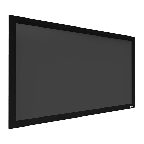
Page 5: Product Overview
PRODUCT OVERVIEW Using the illustration below, identify the frame ordered, and refer to the pages listed for further instructions. Standard Split... -
Page 6: Standard Frame Installation
STANDARD - FRAME INSTALLATION Parts in the Box Installation requires two or more people. The product weighs up to 225 lbs. Please use safe lifting and rigging techniques. 2 x Horizontal Frames 2 x Vertical Frames Hardware Kit 2 x Wall Brackets Wall Bracket 1 pair Gloves 4 x Corner Brackets... - Page 7 STANDARD - FRAME INSTALLATION...
- Page 8 STANDARD - FRAME INSTALLATION Slide corner brackets into each end of the vertical frames Attach the horizontal frames at the either end of the vertical frames.
- Page 9 STANDARD - FRAME INSTALLATION Be sure that corners are square to the eye. Finger tighten only at this point. Square the frame before final tightening of the set screws.
- Page 10 STANDARD - FRAME INSTALLATION Tighten the set screws using the provided tool after squaring the frame. DO NOT use an impact or drill to tighten!! You will damage the frame. Verify that the frame is square by measuring both diagonal corners. Measurements must be within 1/8” of each other. A = B...
-
Page 11: Split Frame Installation
SPLIT - FRAME INSTALLATION Parts in the Box Installation requires two or more people. The product weighs up to 225 lbs. Please use safe lifting and rigging techniques. 2 x Frames 1 x Vertical Support Bar Hardware Kit 2 x Wall Brackets Wall Bracket 1 x Gloves 8 x Corner Brackets... - Page 12 SPLIT - FRAME INSTALLATION...
- Page 13 SPLIT - FRAME INSTALLATION Install the t-slot nuts in the horizontal frame pieces before installing the corner brackets. Slide corner brackets into each end of the vertical frames...
- Page 14 SPLIT - FRAME INSTALLATION Attach the horizontal frames at the either end of the vertical frames. Be sure that corners are square to the eye. Finger tighten only at this point. Square the frame before final tightening of the set screws.
- Page 15 SPLIT - FRAME INSTALLATION Use the splice bars to attach the horizontal frames at the center. a. Slide splice bars into the split horizontal frame b. Push frames together and tighten set screws channels...
- Page 16 SPLIT - FRAME INSTALLATION...
- Page 17 SPLIT - FRAME INSTALLATION A = B Tighten the set screws using the provided tool after squaring the frame. DO NOT use an impact or drill to tighten!! You will damage the frame. Verify that the frame is square by measuring both diagonal corners. Measurements must be within 1/8” of each other.
- Page 18 SPLIT - FRAME INSTALLATION...
-
Page 19: Attaching Material - Black Diamond
ATTACHING MATERIAL - BLACK DIAMOND WHEN HANDLING AND UNROLLING THE BLACK DIAMOND MATERIAL DO NOT KINK IT! Once the material is kinked it is permanently damaged. Roll material out face down inside the frame. Remove black rubber bumpers and spread post attachments out evenly by sliding them down the channel. - Page 20 ATTACHING MATERIAL - BLACK DIAMOND Starting in the middle of each horizontal and vertical, bungee the middle of each side, then work your way outward, completing a side at a time. If there are waves/ creeze in the material, try adjusting the position of the posts.
-
Page 21: Attaching Material - Solar, Slate, Pure
ATTACHING MATERIAL - SLATE / PURE / SOLAR... - Page 22 ATTACHING MATERIAL - BLACK DIAMOND Starting in the middle of each horizontal and vertical, snap/bungee the middle of each side, then work your way outward, completing a side at a time.
-
Page 23: Screen Mounting
SCREEN MOUNTING STANDARD SPLIT... -
Page 24: Screen Mounting - Standard Frame
SCREEN MOUNTING - STANDARD FRAME Install wall brackets onto a structured surface. LEVEL " (8.89 cm) Top Of Frame " (6.03 cm) Top of Viewing... - Page 25 SCREEN MOUNTING - STANDARD FRAME Hang screen from the outer channel of the frame on the wall bracket.
-
Page 26: Screen Mounting - Split Frame (A / B)
SCREEN MOUNTING - SPLIT FRAME SPLIT - A Use Split A mounting when vertical supports bars are not being installed. SPLIT - B Use Split B mounting when vertical supports bars are being installed. - Page 27 SCREEN MOUNTING - SPLIT FRAME - A inch/cm Top Of Frame LEVEL " (8.89 cm) " (6.03 cm) Top of Viewing inch/cm - 1/4” = (0�635 cm) LEVEL " (8.89 cm)
- Page 28 SCREEN MOUNTING - SPLIT FRAME - A Hang screen from the outer channel of the frame on the wall bracket.
- Page 29 SCREEN MOUNTING - SPLIT FRAME - B Top Of Frame LEVEL " " (1.27 cm) SPACER (8.89 cm) " (6.03 cm) Top of Viewing...
- Page 30 SCREEN MOUNTING - SPLIT FRAME - B...
-
Page 31: Notes
NOTES... - Page 32 Screen Innovations 9715-B Burnet Rd, Suite 400 Austin, TX 78758 512.832.6939 www.screeninnovations.com...
Need help?
Do you have a question about the 7 Fixed and is the answer not in the manual?
Questions and answers