
Related Manuals for Bray 71 Seires


Summary of Contents for Bray 71 Seires
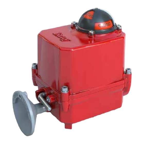
- Page 1 Series 71 Modulating Controller ELECTRIC ACTUATOR Installation, Operation and Maintenance Manual BRAYCOMMERCIALDIVISION.COM THE HIGH PERFORMANCE COMPANY...
- Page 2 This Page Intentionally Left Blank...
-
Page 3: Table Of Contents
6.1.6 FB Pot Header - Required Connection 6.1.7 Heater Header 6.1.8 Motor - Required Connection 7.0 Troubleshooting Guide 7.1 Resolving Issues 7.3 Potentiometer Adjustment FOR MORE INFORMATION ON THIS PRODUCT AND OTHER BRAY PRODUCTS PLEASE VISIT OUR WEBSITE – www.braycommercialdivision.com... -
Page 4: Definition Of Terms
Series 71 – Modulating Controller - Electric Actuator Installation, Operation and Maintenance Manual READ AND FOLLOW THESE INSTRUCTIONS SAVE THESE INSTRUCTIONS DEFINITION OF TERMS WARNING Indicates a potentially hazardous situation which, if not avoided, could result in death or serious injury. CAUTION Indicates a potentially hazardous situation which, if not avoided, may result in minor or moderate injury. -
Page 5: Safety
Series 71 – Modulating Controller - Electric Actuator Installation, Operation and Maintenance Manual SAFETY Hazard Free Use This device left the factory in proper condition to be safely installed and operated in a hazard-free manner. The notes and warnings in this document must be observed by the user to ensure hazard-free operation of this device. -
Page 6: Quick Start Guide
4. Set the Feedback (Output) signal type. 5. Verify (or adjust) the travel limits in the actuator. a. Bray actuators are shipped with the travel switches in the factory default position – close travel limit set at 0 degrees and the open travel limit at 90 degrees. -
Page 7: Description Of Operation
DESCRIPTION OF OPERATION The Bray Series 71 Servo provides complete modulating control and monitoring of the Bray Series 71 Electric Actuator. The basic function of the S71 Servo is to position the S71 Actuator in response to a command signal from a process controller. -
Page 8: User Interface
Series 71 – Modulating Controller - Electric Actuator Installation, Operation and Maintenance Manual USER INTERFACE The S71 Servo features a rich, LED-based menu that displays both configurable settings and operational status. Indicators are grouped together based on function, shown by their respective label(s). Without any user interaction, the S71 Servo will display the factory default product settings, valve status, and fault status. -
Page 9: Configurable Settings
Series 71 – Modulating Controller - Electric Actuator Installation, Operation and Maintenance Manual 5.1.1 Configurable Settings Settings can be changed locally by utilizing the push-button associated with each product setting. Each push-button is labeled and placed below a set of LEDs, with individual labels corresponding to the setting. Settings are changed using the push-button. -
Page 10: Operating Modes
Series 71 – Modulating Controller - Electric Actuator Installation, Operation and Maintenance Manual Output Signal Type - Configurable Output signals report the position of the valve under control, based on the magnitude of the signal. The minimum value corresponds to the closed position and the maximum value to the open position. -
Page 11: Manual Operation
Series 71 – Modulating Controller - Electric Actuator Installation, Operation and Maintenance Manual 5.2.2 Manual Operation Manual operation of the actuator is performed via declutchable handwheel. The S71 Servo will continue to operate as if in remote mode, though it will not be able to actuate to a new setpoint until the manual mode is disengaged. -
Page 12: Status Indication
Series 71 – Modulating Controller - Electric Actuator Installation, Operation and Maintenance Manual Status Indication These are all indicators that report key information on the operation and functional status of the S71 Servo and actuator. Figure 6 - S71 Servo Setting Buttons and Status Indication LEDs 5.3.1 Direction Indicators The Open (green) and Close (red) indicators, located at the top left of the... -
Page 13: Fault Status
Series 71 – Modulating Controller - Electric Actuator Installation, Operation and Maintenance Manual 5.3.2 Fault Status The Fault LED, located at the bottom left, will turn on during a fault condition. The occurrence of a fault indicates that user intervention is required to restore operation, and these indicators attempt to provide the diagnostic information needed to accomplish this. -
Page 14: Heartbeat
Series 71 – Modulating Controller - Electric Actuator Installation, Operation and Maintenance Manual CAUTION If cams or potentiometer are adjusted, the previous calibration settings will not apply to the new setup. Re-run the calibration routine to avoid unexpected behavior. 5.3.4 Heartbeat The heartbeat indicator, at the top right, serves as status indicators for the S71 Servo. -
Page 15: Hardware Description
Series 71 – Modulating Controller - Electric Actuator Installation, Operation and Maintenance Manual HARDWARE DESCRIPTION Terminal Connections WARNING Turn off all power and lockout/tag out service panel before installing or modifying any electrical wiring. There are two categories of connections: voltage level and connection type. Field terminals are provided on the unit for the landing of stripped wires, connecting the S71 Servo to the field wiring needed for it successfully operate. - Page 16 Series 71 – Modulating Controller - Electric Actuator Installation, Operation and Maintenance Manual NOTICE Refer to the actuator wiring diagram for wire gauge, voltage, and temperature limits of the terminal blocks. All actuator connections should match the actuator wiring diagram. Figure 12: 24V S71 Servo wiring diagram...
-
Page 17: Input Signal - Required Connection
Series 71 – Modulating Controller - Electric Actuator Installation, Operation and Maintenance Manual ACTUATOR FIELD WIRING TERMINALS - AUX AUX OPEN · 12-22 AWG MAX RANGE, 18 AUX CLOSE AWG RECOMMENDED · SCREW CLAMP WITH WIRE AUX COM PROTECTOR · 105 °C, 300V MIN RATED WIRE N.C. -
Page 18: Auxiliary Signals
Series 71 – Modulating Controller - Electric Actuator Installation, Operation and Maintenance Manual 6.1.3 Auxiliary Signals Connection for the auxiliary switches, which indicate to the customer when an end of travel set point has been reached. Auxiliary switches are voltage- free contacts and powered by the customer. -
Page 19: Heater Header
If the actuator has an internal heater, then the heater wires are terminated at this connection. The heater will be powered by the input power connection. Only Bray supplied heaters should be connected to the S71 Servo. 6.1.8 Motor - Required Connection Connections for the motor that operates the actuator. -
Page 20: Troubleshooting Guide
Series 71 – Modulating Controller - Electric Actuator Installation, Operation and Maintenance Manual TROUBLESHOOTING GUIDE WARNING Turn off all power and lockout/tag out service panel before installing or modifying any electrical wiring. Refer to the actuator manual before adjusting or replacing any actuator components. - Page 21 Series 71 – Modulating Controller - Electric Actuator Installation, Operation and Maintenance Manual Clearing Fault Conditions Fault Condition Possible Causes Possible Solutions Command Signal Fault Command signal does not Adjust the Input setting to match input setting match the command signal used S71 Servo is incorrectly Verify wire connections...
-
Page 22: Potentiometer Adjustment
Series 71 – Modulating Controller - Electric Actuator Installation, Operation and Maintenance Manual Potentiometer Adjustment If a feedback potentiometer fault occurs, the issue is due to the potentiometer settings. This routine will allow the customer to quickly adjust the potentiometer back into the proper range. Place the unit in manual mode. - Page 23 All statements, technical information, and recommendations in this bulletin are for general use only. Consult Bray representatives or factory for the specific requirements and material selection for your intended application. The right to change or modify product design or product without prior notice is reserved.
Need help?
Do you have a question about the 71 Seires and is the answer not in the manual?
Questions and answers