Subscribe to Our Youtube Channel
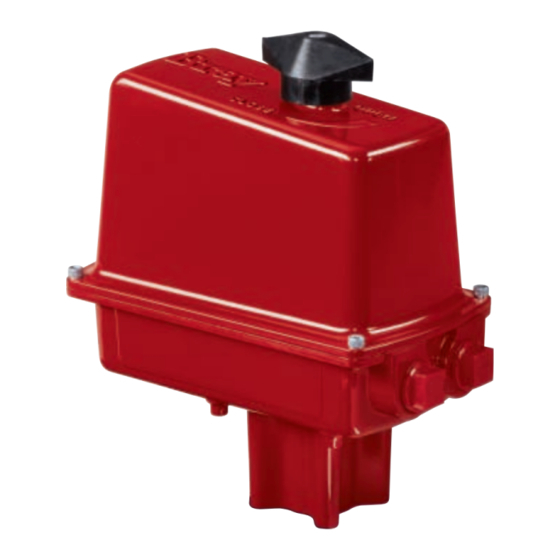
Summary of Contents for Bray 73 Series
- Page 1 SERIES 73 ELECTRIC ACTUATOR OPERATION AND MAINTENANCE MANUAL High Performance Company...
-
Page 3: Table Of Contents
........................auxiliary switches ....................Typical Single Phase & DC Wiring Diagrams ............appendix a basic tools ........................ appendix b actuator troubleshooting chart ............... for information on this product and other bray products please visit us at our webpage - www.bray.com... -
Page 4: Safety Instructions: Definitions Of Terms
BRAY Series 73 Electric Actuator Operation and Maintenance Manual 1.0 s afeTy nfOrmaTIOn efInITIOn Of erms WARNING indicates a potentially hazardous situation which, if not avoided, could result in death or serious injury. CAUTION indicates a potentially hazardous situation which, if not avoided, may result in minor or moderate injury. -
Page 5: Introduction
The motor has a spring loaded brake that activates nTrODuCTIOn when power is removed from the unit. The brake prevents The Bray Series 73 is a quarter turn electric actuator with the spur gears from being back driven. manual override for use on any quarter turn valve requiring General Electrical Schematic up to 600 Lb-In of torque. -
Page 6: Installation
Ounting tO a alVe the actuator is in line with the valve stem. If possible, All Bray Series 73 electric actuators mount directly to Bray use an intermediate position (i.e. valve disc/stem and butterfly valves. With proper mounting hardware, the S73 actuator half open). -
Page 7: Electrical Installation
BRAY Series 73 Electric Actuator Operation and Maintenance Manual lectrical nstallatiOn 1. Check the actuator’s nametag for confirmation of: CAUTION Torque Rating, Quarter Turn Time, Duty Rating and Power Supply. Example ‘A’ below is shown for S73 PN: 73-0102-113D5-536 Do not reverse motor instantaneously when it is still 2. -
Page 8: Multiple Actuator Wiring
BRAY Series 73 Electric Actuator Operation and Maintenance Manual Multiple Actuator (Parallel) Wiring A voltage is present on both motor windings, these volt- ages are out of phase and different in magnitude. If these windings are connected to one another as shown in the INCORRECT diagrams, this will interfere with the motor performance. - Page 9 BRAY Series 73 Electric Actuator Operation and Maintenance Manual Orrect OnnectiOns To eliminate this “BACK FEEDING PARALLEL” driv- ing, we suggest separate contacts for each actuator. If we redraw the diagram for the #1 actuator having reached its fully open travel position and having tripped its open travel limit switch.
-
Page 10: Travel Limit Switch Adjustment
To prevent condensation from forming inside the actuator, 3. Align the fastening hole in the bracket with the Bray offers an optional heater. The heater is a PTC (Posi- threaded screw hole in the plate. Fasten the heater tive Temperature Coefficient) type, which has a unique to the switchplate. -
Page 11: Auxiliary Switches
BRAY Series 73 Electric Actuator Operation and Maintenance Manual switch ( ield install Of auxiliary OOls equired For terminal wiring Screwdriver, 3/16” flat tip blade The maximum allowable auxiliary switch configuration is shown in the illustrations below for each size of actuator. -
Page 12: Typical Single Phase & Dc Wiring Diagrams
BRAY Series 73 Electric Actuator Operation and Maintenance Manual Typical actuator wiring diagrams shown for single phase A.C. and D.C. motorized units. Diagrams show actuators in their fully closed positions. -
Page 13: Appendix A Basic Tools
BRAY Series 73 Electric Actuator Operation and Maintenance Manual PPenDIx asic OOls equired fOr nstallatiOn OMMOn nits Position Indicator Knob Screwdriver, 3/4” tip flat All switches, heater kit Screwdriver, No.1 phillips Terminal strip wiring Screwdriver, 3/16” flat tip Cam adjustment Hex key, 5/64”... -
Page 14: Actuator Troubleshooting Chart
BRAY Series 73 Electric Actuator Operation and Maintenance Manual PPenDIx ctuatOr rOubleshOOting hart Problem Possible cause Solutions Actuator does not operate Cams are depressing travel switch Adjust cams to their correct positions Override is engaged/shaft depressed Apply electricity to cancel manual... - Page 15 BRAY Series 73 Electric Actuator Operation and Maintenance Manual OTes...
- Page 16 A Division of BRAY INTERNATIONAL, Inc. 13333 Westland East Blvd. Houston, Texas 77041 281.894.5454 FAX 281.894.9499 www.bray.com Bray is a registered trademark of BRAY INTERNATIONAL, Inc. ® © 2009 Bray International. All rights reserved. OM-73-001 07-2010...


Need help?
Do you have a question about the 73 Series and is the answer not in the manual?
Questions and answers