
Subscribe to Our Youtube Channel
Related Manuals for Megger HPG AC Series


Summary of Contents for Megger HPG AC Series
- Page 1 HPG XX-AC / HPG XX-H / HPG XX-D High Voltage Test Sets (Controlled by High Voltage Control Set HSW 3-2) OPERATION MANUAL Issue: A (11/2019) –EN Artcle number: 128312070...
- Page 3 Megger All rights reserved. No part of this handbook may be copied by photographic or other means unless Megger have before-hand declared their consent in writing. The content of this handbook is subject to change without notice. Megger cannot be made liable for technical or printing errors or shortcomings of this handbook. Megger also...
- Page 4 Megger. All warranty claims versus Megger are hereby limited to a period of 12 months from the date of delivery. Each component supplied by Megger within the context of warranty will also be covered by this warranty for the remaining period of time but for 90 days at least.
-
Page 5: Table Of Contents
Table of Contents Description ..................8 General .................... 8 Functions ..................8 High Voltage Test Configurations ............ 9 Technical Data ................10 Scope of Delivery ................11 Operating Panel and Connection Panel ........12 Test System Installations ............14 HPG XX-AC ................... 14 3.1.1 HPG 35-AC ................... - Page 6 Mains Connection ................25 Startup ..................26 Switching On (Ready for Operation) ..........26 Switching On (Ready for HV) ............27 Selecting the Test Voltage............. 27 Voltage Measurement ..............27 7.4.1 Voltage Measurement in Portable Installation ....... 28 7.4.2 Voltage Measurement in Test Van Installation ......29 Using the Timer ................
- Page 7 List of Figures Figure 1 : Operating panel ............. 12 Figure 2 : Connection panel ............13 Figure 3 : HPG 35-AC, HPG 58-AC or HPG 78-AC installation ..14 Figure 4 : HPG 50-H, HPG 80-H or HPG 110-H installation ..16 Figure 5 : HPG 50-D or HPG 80-D installation ......
-
Page 8: Description
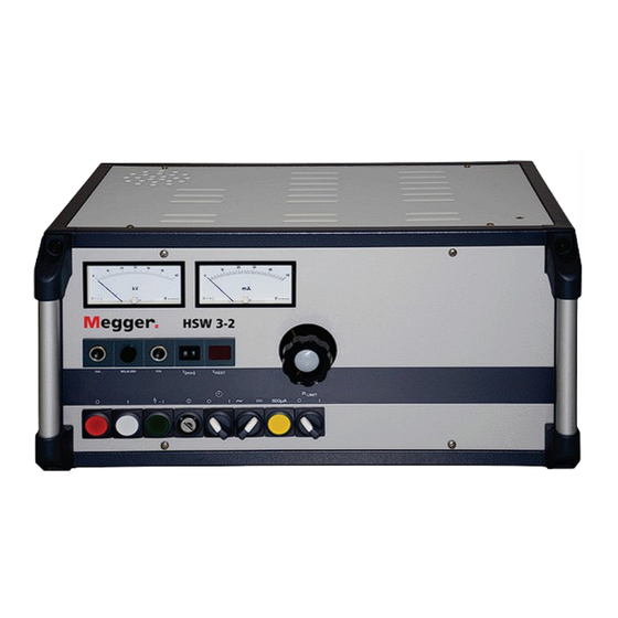
Description General The control unit HSW 3-2 is part of a complete high voltage test system and is used to trigger the HV devices and to display current and voltage. The instrument disposes of some control elements and indicator lamps for operation status indication. The HSW 3-2 is either delivered as a stand-alone version for portable operation or as table version for test van assembly. -
Page 9: High Voltage Test Configurations
High Voltage Test Configurations The HSW 3-2 can be used as control unit for the following high voltage test sets: HPG 35-AC 0 – 35 kV HPG 58-AC 0 – 58 kV HPG 78-AC 0 – 78 kV HPG 50-H 0 –... -
Page 10: Technical Data
Technical Data Mains voltage: 230 V + 6 / - 10 % Mains frequency: 45 – 60 Hz Operating current: 16 A (max.) Power rating: 3.5 kVA Circuit breaker: 10 A Output voltage: 0 – 250 V Meter U: kV-Meter 0 … 60 kV 0 …... -
Page 11: Scope Of Delivery
Scope of Delivery Control unit HSW 3-2 Cable set: VL 70 consists of: 2.1. NSP – lead (5 m) VSK 5 2.2. Mains cable (2.5 m) NKG S 2.3. Earth connection lead 5 m with clamp EK 1 2.4. Earth connection lead for transformator EK 1 2.5. -
Page 12: Operating Panel And Connection Panel
Operating Panel and Connection Panel Figure 1 : Operating panel Analog volt meter Analog ampere meter Rotary knob for variac adjustment Rotary switch for limiting resistance Pushbutton for test range selection Rotary switch for selection of AC/DC operation Rotary switch for timer Key switch Lighted pushbutton, green - HV ON 10. -
Page 13: Figure 2 : Connection Panel
Figure 2 : Connection panel 17. Socket for connection lead to the high voltage transformer 18. Socket for earthing lead 19. Socket for direct HV measurement (optional for test van installations) 20. Label 21. Identification plate 22. Socket for connecting the emergency off switch 23. -
Page 14: Test System Installations
Test System Installations Since the HSW 3-2 control unit can be operated with several test systems, the specific test system installations are described in the following section. HPG XX-AC The 50 Hz alternating current is directly tapped on the output of the cast resin-insulated transformer. -
Page 15: Hpg 35-Ac
The HV transformer should be connected with the test object using a direct connection (wire or bus bar). It is also possible to connect them with a short cable connection (6 to 10 m). Longer cable connections do not make sense, since the remaining test performance would be too low. -
Page 16: Hpg Xx-H
HPG XX-H 230 V (+6% / -10%) 45 – 60 Hz Figure 4 : HPG 50-H, HPG 80-H or HPG 110-H installation 3.2.1 HPG 50-H This test system consists of the following components: Control unit HSW 3-2 HV transformer HTR 35-1 HV rectifier HGL 80 Cable set... -
Page 17: Hpg 110-H
3.2.3 HPG 110-H This test system consists of the following components: Control unit HSW 3-2 HV transformer HTR 78-1 HV rectifier HGL 120 Cable set VL 70 Discharge rod EST 150 HPG XX-D 230 V (+6% / -10%) 45 – 60 Hz DCS 140 Figure 5 : HPG 50-D or HPG 80-D installation... -
Page 18: Hpg 50-D
3.3.1 HPG 50-D This test system consists of the following components: Control unit HSW 3-2 HV transformer HTR 35-1 HV rectifier HGL 70-R HV rectifier HGL 70-D Voltage doubler capacitor DCS 140 AC voltage connection Insulated support Cable set VL 70 Connecting piece 10. -
Page 19: Safety
Safety Figure 6 : Safety advices (USA and Germany) All HPG high voltage test sets generate dangerous contact voltages > 1 kV. Hence, the Instrument must be operated by specialists or personnel who have been trained or instructed in the use of the instrument. -
Page 20: Safety Terms According To Vde 0104
Safety Terms According to VDE 0104 The term in parentheses describes the position number within the VDE 0104 (italic). 4.2.1 READY FOR MAINS CONNECTION The white pilot lamp (10) indicates the presence of mains supply. The pilot lamp (10) is permanently lit and cannot be switched off. 4.2.2 READY FOR OPERATION (Pos. -
Page 21: Portable Test Equipment
4.2.5 Portable Test Equipment (Pos. 4.5) According to VDE 0104 the complete test set up comprising the HSW 3-2, its connections including the termination of the cable under test constitutes a Portable Test Unit being used at a test site without secure contact protection. The same goes for the termination(s) of the cable to be tested. -
Page 22: Placing The Device
Placing the Device Preferably, the HSW 3-2 should be placed outside of the forbidden area. In a portable installation, the high voltage source should preferably be placed within the station and the door should be closed. This creates a test site with secure contact protection. A HSW 3-2 operated in a test van is already placed in a safe position and no further arrangements have to be made. -
Page 23: Connecting The Device
Connecting the Device Prior to connecting the HV equipment to the cable under test, the five safety rules must always be followed: De-energise Protect against re-energising Confirm absence of voltage Ground and short-circuit Cover up or bar-off neighbouring energised parts... -
Page 24: Earthing
Earthing a. The control unit HSW 3-2 has to be earthed. For this purpose, the earthing terminal (18) is connected to a reliable protective earth by means of the earthing lead EK 1. Figure 7 : Connection panel of the HTR b. -
Page 25: Connecting The Control Unit To The Hv Transformer
Connecting the Control Unit to the HV Transformer With the VSK 5 lead the appropriate socket of the control unit (17) is connected to the socket (25) of the HV transformer. If the HSW 3-2 is operated in a test van, the HV connection is already installed. -
Page 26: Startup
Startup After all connections are installed and verified, the device can be switched on. Switching On (Ready for Operation) In order to switch the device on, the key switch (8) has to be turned in ON position and the rotary switch (3) has to be turned in null position (fully to the left). -
Page 27: Switching On (Ready For Hv)
Switching On (Ready for HV) The device must be in operating state (see 7.1). The green pushbutton (9) has to be pressed. The red pilot lamp (11) indicates that the device is now ready for HV. Selecting the Test Voltage The device must be ready for HV (see 7.2). -
Page 28: Voltage Measurement In Portable Installation
7.4.1 Voltage Measurement in Portable Installation Since no measuring resistance can be used in portable operation, the voltage is measured at a tertiary winding of the HV transformator. Figure 7 shows the appropriate simplified diagram. According to this diagram, the voltage of the tertiary winding is displayed as output voltage. -
Page 29: Voltage Measurement In Test Van Installation
7.4.2 Voltage Measurement in Test Van Installation If the HSW 3-2 is operated in a test van, the generated HV can be directly measured. Figure 8 shows the appropriate simplified diagram. Thereby, the low end of the resistor is connected to the appropriate socket (19) of the control unit (see figure 2). -
Page 30: Leakage Current Measurement
Leakage Current Measurement The leakage current is indicated at the ampere meter (2). The rotary switch (6) can be used to toggle between AC and DC operation. The basic measurement range is 50 mA. By pressing the yellow pushbutton (5), the measurement range can be temporary (as long as the button is pressed) set to 500 µA. -
Page 31: Note
7.7.3 Note The heat generated at the limiting resistor is eliminated by a fan. Hence, the air outlets must be kept unobstructed. The fan is directly connected to the mains input. A cut-off has not been provided because even after switching off the instrument, the residual heat of the limiting resistance has to be dissipated. -
Page 32: Disconnecting The Cable Under Test
Disconnecting the Cable Under Test Important Safety Advice: After switching off the control unit, voltage might still be present, although the voltmeter indicates no residual voltage. Thus, the disconnection has to be performed very cautiously! The device must be switched off and the key switch must be in OFF position. - Page 34 Tento symbol indikuje, že výrobek nesoucí takovéto označení nelze likvidovat společně s běžným domovním odpadem. Jelikož se jedná o produkt obchodovaný mezi podnikatelskými subjekty (B2B), nelze jej likvidovat ani ve veřejných sběrných dvorech. Pokud se potřebujete tohoto výrobku zbavit, obraťte se na organizaci specializující se na likvidaci starých elektrických spotřebičů...
Need help?
Do you have a question about the HPG AC Series and is the answer not in the manual?
Questions and answers