Table of Contents
Advertisement
Quick Links
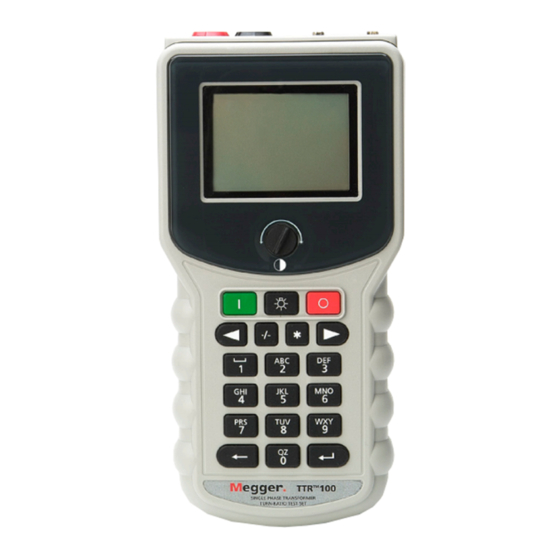
Instruction Manual AVTMTTR100
Transformer Turn Ratio Test Set
Catalog Nos. TTR100 and TTR100-1
Read the entire manual before operating.
Antes de operar este producto lea este manual enteramente.
for
Single-Phase Handheld TTR
High-Voltage Equipment
Aparato de Alto Voltaje
AVTMTTR100-ENG
Rev. 6
Nov 2015
M
2621 Van Buren Ave
Norristown, PA 19403-2329
610-676-8500
www.megger.com
Advertisement
Table of Contents


Need help?
Do you have a question about the AVTMTTR100 and is the answer not in the manual?
Questions and answers