
Subscribe to Our Youtube Channel
Related Manuals for Megger SVERKER 650


Summary of Contents for Megger SVERKER 650
- Page 1 SVERKER 650 Relay Test Unit User’s Manual Art No. ZP-BA01E Doc. BA0143KE V04A 2016...
-
Page 2: Table Of Contents
Contents 1 Safety ............. 4 1.1 Symbols on the instrument ......4 1.2 Safety instructions ........4 2 Introduction ............. 6 3 Control panel ............. 8 4 Operating instructions ............10 4.1 General ............10 4.2 Testing current relays .........10 4.3 Testing voltage relays .........11 4.4 Testing power relays ........11 4.5 Time measurement ........12 4.6 Time measurement of over-current and over-... - Page 3 © 2007-2015, Megger Sweden AB. All rights reserved. The contents of this manual are the property of Megger Sweden AB. No part of this work may be reproduced or transmitted in any form or by any means, except as permitted in written license agreement with Megger Sweden AB. Megger Sweden AB has made every reasonable attempt to ensure the completeness and accuracy of this document.
-
Page 4: Safety
IEC 60227 or IEC 60245. Mains supply cables certified or approved by a recognized testing authority are regarded as meeting this requirement. SVERKER 650 ZP-BA01E BA0143KE... - Page 5 Unplug the instrument from the mains supply when it is left unattended or not in use. Refer all servicing to Megger authorized personnel. If you need to return the instrument, please use either the original crate or one of equivalent strength...
-
Page 6: Introduction
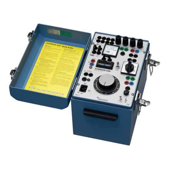
2 INTRODUCTION Introduction The SVERKER 650 is a rugged instrument but it still should be handled with care. The relay testing unit is electrically fully isolated in all measuring ranges, except for the mains output. The set of resistors is not connected with the rest of the relay testing unit set. - Page 7 3 CONTROl PANEl BA0143KE ZP-BA01E SVERKER 650...
-
Page 8: Control Panel
▪ load regulation 3 % ▪ line regulation less than 4 % 110 V 0.3 A 110-125 V CA Capacitor 10 μf/450 V AC for reactive power relays Automatic cut-out for the mains voltage, 4 A SVERKER 650 ZP-BA01E BA0143KE... - Page 9 Voltage adjustment terminal U6 Terminal for connection of a resistor on the primary side of the output transformer Terminal for an external ammeter Terminal for external start and stop of timer Terminal for starting external operation BA0143KE ZP-BA01E SVERKER 650...
-
Page 10: Operating Instructions
Read the manual and comply with the 0-10 A (85 V), 0-40 A (25 V) or 0-100 A (10 V). Safety instructions, see page 5, before us- ing SVERKER 650. Increase the current to the operating value Always comply with local safety regula- using the variable transformer. -
Page 11: Testing Voltage Relays
Use an external measuring instrument for using the variable transformer. better accuracy. Check the current on the ammeter or exter- nal instrument during the test. Note Shift polarity of the voltage or current if func- tion has failed to appear. BA0143KE ZP-BA01E SVERKER 650... -
Page 12: Time Measurement
Note The timer can be started externally by a make at terminal (W3). The switch (S1) should then be in position “ON+TIME” or “OFF+TIME”. When using the timer internally, the terminal (W3) has to be short-circuited. SVERKER 650 ZP-BA01E BA0143KE... -
Page 13: Time Measurement Of Under-Current And Under-Voltage Relays
Connect the tripping circuit. Set the changeover switch for time measure- ment in position make/break. Set the switch in position “ON”. Increase the voltage/current until the relay picks up. Then set the switch in position “OFF + TIME”. BA0143KE ZP-BA01E SVERKER 650... -
Page 14: Specifications
5 SPECIfICATIONS Specifications Specifications SVERKER 650 Outputs Current outputs, CA Specifications are valid at nominal input voltage and an ambient Range No-load Output Load / un- temperature of +25°C, (77°f). Specifications are subject to voltage voltage (min) load times On change without notice. - Page 15 5 SPECIfICATIONS BA0143KE ZP-BA01E SVERKER 650...
- Page 16 ▪ Insulation Power Factor (C&DF) Test Equipment worldwide. ▪ Insulation Resistance Test Equipment Megger is certified according to ISO 9001 and 14001. ▪ Line Testing Equipment Megger is a registered trademark. ▪ Low Resistance Ohmmeters ▪...
Need help?
Do you have a question about the SVERKER 650 and is the answer not in the manual?
Questions and answers