
Related Manuals for Megger INGVAR


Summary of Contents for Megger INGVAR
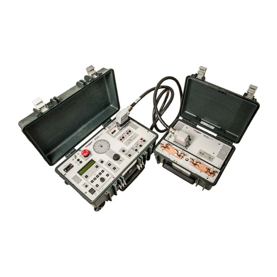
- Page 1 INGVAR Primary Current Injection Test System User’s Manual Art No. ZP-BH05E Doc. BH0654BE 2011...
- Page 3 © 2011, Megger Sweden AB. All rights reserved. The contents of this manual are the property of Megger Sweden AB. No part of this work may be reproduced or transmitted in any form or by any means, except as permitted in written license agreement with Megger Sweden AB. Megger Sweden AB has made every reasonable attempt to ensure the completeness and accuracy of this document.
-
Page 4: Table Of Contents
6.10 How to arrange bars ........32 Current generation ........... 10 6.11 FAQ ............32 The measurement section contains/provides ....10 7 How to use INGVAR ......34 2.2 Fields of application ........11 7.1 How to generate current ......34 2.3 Reservations ..........11 7.2 Rules of thumb when generating current ...35... - Page 5 Rules of thumb ............46 8 Application examples ......48 8.1 Testing a low-voltage circuit breaker...48 Measuring the tripping limit (normal generation) ..48 Measuring the tripping time ........48 Instantaneous trip unit measurement ......48 Measure the instantaneous trip time ......49 8.2 Testing the ratio of a current transformer ...49 Example ..............
-
Page 6: Safety
Make certain that all personnel who work with INGVAR have been trained in its use and that all ap- 1. Read / Follow / Retain all instructions plicable safety precautions are taken. - Page 7 3. Grounding (Earthing) 7. Use ▪ ▪ INGVAR can be used only in electrical systems with Do not use the instrument for any purpose other single Ground. User must verify before connecting than indicated by the manufacturer. this unit to power, that High Voltage Ground and ▪...
- Page 8 10. Power sources 15. Damage ▪ ▪ Only connect INGVAR to an outlet protected with Do not use INGVAR if the test leads appear damaged. max 16 A overcurrent protection. ▪ Do not continue using a damaged INGVAR. Using a ▪...
- Page 9 1 SAFETY BH0654BE ZP-BH05E...
-
Page 10: Introduction
It is not necessary to clear the display first. can sense the phase angle and adapt subsequent gen- ▪ You can save different settings for INGVAR in ten different eration operations so that they all start at the current’s memories. -
Page 11: Fields Of Application
INGVAR is primarily intended for: only for temporary (short-duration) current genera- ▪ Testing of protective relay equipment (primary injection tion. Do not use INGVAR for long-term generation at testing). full current. See the product specifications in chapter ▪ Testing of breakers with overcurrent tripping. -
Page 12: Panels
3 PANELS Panels 3.1 Control Unit panel ▪ Miniature circuit breaker (F1) connected to the current generation circuitry. It can be operated More detailed descriptions of the display and the manually and used as a disconnector to prevent menu options appear in chapter 4 ”Display” and unintentional generation ▪... - Page 13 ▪ Recall or save settings for INGVAR in 10 memories. ▪ APPL Here you set INGVAR for the following applications: a) Normal use.
- Page 14 3 PANELS ▪ OFF, stops current generation STOP INPUT, here you enter the stop condition. When this condition is met, the current generation and timer stops. The measured value can be frozen (held). , activates the automatic shutoff-function. ING- AUTO VAR will automatically stop generating current after a specified period of time.
-
Page 15: Cables
3 PANELS 3.2 Current Unit panel 3.3 Cables ▪ CONTROL UNIT, input terminal for connection to INGVAR Control Unit ▪ OUTPUT, current output Standard cables Terminals for parallel or serial configuration ▪ Sensor for the output configuration (parallel/serial) Interconnection cable ▪... -
Page 16: Optional Cables
3 PANELS Optional cables Current cables Interconnection cable, 5 m (16 ft) GA-12705 Interconnection cable, 10 m (33 ft) GA-12710 Current cable set 2 x 0.5 m (1.6 ft) 3 x 120 mm GA-12305 with end-bars. Standard current cable set, 2 x 2 m (6.5 ft) , 120 mm Grounding cable Cable for protective grounding, 5 m (16 ft), 16 mm Mains cable... - Page 17 2 INTRODUCTION BH0654BE ZP-BH05E...
-
Page 18: Display
You can scroll both up and down ▪ Presents measured values. When special applications are ▪ Presents INGVAR´s settings. activated ▪ Guides you by providing helpful messages, warnings and When a special application is activated this is indicated prompts. - Page 19 4 DISPLAY BH0654BE ZP-BH05E...
-
Page 20: Menu Options
"AMMETER" menu option. In the "V/A METER" display. menu option you can set INGVAR’s second amme- You can only select a menu option while INGVAR is in ter ("A-METER 2") and INGVAR’s voltmeter. In the the OFF state (i.e. not generating). -
Page 21: V/A Meter
Seconds are displayed V/A Meter up to 1 min. Menu Settings Description DC- Meas- On/Off INGVAR can be set to measure urement DC-current (A-meter 1 and 2) and A-Meter 2, Auto Range is selected automati- DC-voltage (V-meter). See note. Range cally. -
Page 22: Memory And Application Menu Options
0 are loaded automatically. This means that if you want a specific set of settings to be used the next time you turn INGVAR on, you can save them in memory 0 before turning INGVAR off. There is one... -
Page 23: Application
Turn the Select/set knob until the number of the desired memory appears. Press APPLICATION In this menu option you can change INGVAR’s mode of operation for different types of tests. The available settings are listed in the table below. Application... -
Page 24: How To Install Ingvar
When you are changing the connec- tions make sure that current not can When you connect INGVAR to the object being test- be generated accidentally. Disconnect ed, you should check that the contacts on the connec- the mains supply or switch the minia- tors are clean and that the cable clamps are placed as ture breaker F1 to the 0-position. -
Page 25: Series Connection
6 HOW TO INSTALL INGVAR 6.3 Series connection 6.4 Parallel connection Use series connection when you want a high voltage Use parallel connection when you need a low internal at a high load impedance. impedance in order to be able go generate high cur- rent. -
Page 26: Connecting The Current Unit To The Control Unit
6 HOW TO INSTALL INGVAR 6.5 Connecting the Current 6.6 Grounding INGVAR Unit to the Control Unit WARNING The Current unit is connected to the Control Unit via a This equipment can be used only in cable with multi-pin connectors. -
Page 27: Connecting Ingvar To The Mains
Unit are functioning when INGVAR is turned on. Mains voltage INGVAR is designed for 100 – 240 V. The mains supply fuse normally is rated 10 A or 16. This will limit the highest output current but it is still possible to get several kA for a short time with a slow 16 A fuse. -
Page 28: Standard Multi-Cable Sets
At each end there is an end-bar intercon- necting the cables. The bar also enables single bolt connection to INGVAR and the test object. See figure below. Impedance of the cable set is very dependent on how cables are arranged. See section How to arrange the cable sets Length 2 x 0.5 m (distance to test object 0.5 m) -
Page 29: Calculate The Impedance
6 HOW TO INSTALL INGVAR Calculate the impedance Number Total cross section Impedance, cables twisted Max. current in Max. continuous Weight (total set) of cables area (mΩ) 20 sec. current 1 pair 120 mm (1 x 120) (L x 0.43) + 0.1... -
Page 30: How To Arrange The Cable Sets
6 HOW TO INSTALL INGVAR 6.9 How to arrange the LOAD cable sets Minimising impedance in cables Just increasing cross-section area helps only to a cer- tain extent. When resistance is low, the major part of the impedance is caused by the reactance. Minimising... - Page 31 6 HOW TO INSTALL INGVAR LOAD LOAD Cables close together but not twisted. Impedance is 1.5 to Cables with opposite current direction 1 meter apart. Im- 2.5 times higher than with twisted cables. pedance is 2 to 4 times higher than with twisted cables...
-
Page 32: How To Arrange Bars
6.10 How to arrange bars 6.11 FAQ Copper-bars are in many cases a better solution than Is it possible to connect INGVAR systems in cables at high currents and short distances and at parallel or series. long load times. Bars must be specially designed for No. - Page 33 5 MENU OPTIONS BH0654BE ZP-BH05E...
-
Page 34: How To Use Ingvar
This chapter describes the functions that you can perform using INGVAR. Complete test procedures are current described in chapter 8 ”Application examples”. Connect INGVAR to the object under test as described in chapter 6. Turn on INGVAR using the mains switch on the Control Unit. -
Page 35: Rules Of Thumb When Generating Current
If the object being tested has a low imped- High currents can generate a great deal of heat in ance connect the Current Unit in parallel. both INGVAR and the object being tested. To avoid Connect it in series if the object has high unnecessary heating, you can: impedance. -
Page 36: Setting Times For Limited-Time Generation (Max Time)
7 HOW TO USE INGVAR 7.4 Setting times for 7.5 Continuous current limited-time generation generation (MAX TIME) If you want to generate current for an unlimited time, i.e. until you shut generation off manually, proceed as If you want to generate current throughout a limited... -
Page 37: Setting Stop Conditions
INGVAR’s internal impedance You can set the stop condition in a number of differ- ent ways. You can use the following combinations: To obtain maximum current from INGVAR proceed as follows: Closing of an external Connect the Current Unit in parallel. -
Page 38: Generating Low Currents
7.8 Generating low 7.9 Generating pulse trains currents You can set INGVAR to generate a pulse-train (inter- mittent current generation at regular intervals, i.e. If you want to improve the accuracy of current set- pulse-pause-pulse-pause etc.). This will continue until... -
Page 39: Holding (Freezing) Measured Values
7.11 Measuring phase measured values angle and polarity The function freezes a measured value when a signal INGVAR can display the phase angle between the cur- arrives at the STOP INPUT or when the current is rent from INGVAR (A-METER) and: interrupted. -
Page 40: Measuring Z, P, R, X, S, Q And Power Factor (Cos Φ)
7 HOW TO USE INGVAR 7.12 Measuring Z, P, R, X, S, Q and power factor (cos ϕ) When INGVAR's voltmeter is activated you can meas- ure impedance (Z), active power (P), resistance (R), reactance (X), virtual power (S), reactive power (Q) and power factor (cos ϕ). -
Page 41: Reading Maximum Current At An
7 HOW TO USE INGVAR 7.13 Reading maximum 7.14 Measuring operating current at an operation limits The highest current value showed on the display at an There are three ways to measure operating limits: operation is stored. ▪ Normal generation. Used when there is little risk for... -
Page 42: Method 2: Manually Controlled Momentary Injection
7 HOW TO USE INGVAR Press briefly. Press TIME to start generation and turn up the Note, however, that current must be sent out current until the protective relay equipment for a period longer than the operating time. operates (pick-up). -
Page 43: Measuring Tripping/Operation Times
7 HOW TO USE INGVAR 7.15 Measuring tripping/ 7.16 Instantaneous trip operation times unit measurement Here, generation continues until the protective relay You can test the instantaneous trip for breakers and equipment operates or the breaker trips. To avoid for protective relay equipment as follows: unnecessary heating or operation of the object being ▪... -
Page 44: Test Circuit Impedance
The test circuit impedance Z consists of current cable impedance and impedance of the test object. Accord- ing to Ohms law I x Z volt is required to push current I through the impedance. If voltage at INGVAR terminals is less, current will be lower than desired. Note... -
Page 45: Selecting Output Configuration And Cables / Conductors
7 HOW TO USE INGVAR 7.18 Selecting output Test object impedance can be estimated from experience, some examples: configuration and cables / ▪ Low Voltage air breaker rated 4 kA: conductors 0.09 - 0.2 mΩ ▪ Low Voltage circuit breaker rated 630 A: 0.3 - 1mΩ... -
Page 46: Rules Of Thumb
7 HOW TO USE INGVAR Rules of thumb ▪ a) Distance max. 0.5 m, current 5 kA (For example Low Voltage Circuit Breaker testing) Minimise cable impedance. Weight is a minor problem. Use cable set with many cables in parallel or bars. - Page 47 5 MENU OPTIONS BH0654BE ZP-BH05E...
-
Page 48: Application Examples
When current first is generated Instantaneous trip unit for a load (while the current is being set), INGVAR measurement adapts itself so that all subsequent generation opera- tions start at the current’s zero-cross-over points. -
Page 49: Measure The Instantaneous Trip Time
INGVAR’s second ammeter ("A-METER 2"). WARNING Make certain that you observe all appli- cable safety regulations and precautions associated with dielectric strength on the secondary side. -
Page 50: Measuring The Polarity Of A Current Transformer
P2 (H2). Basic setting: OPERATE Connect the one of the output terminals on INGVAR’s which is marked with a dot (·) to P2 (H2) on the primary side of the CT. Connect the other output terminal to P1 (H1). -
Page 51: Testing A Direct Acting Automatic Recloser
8.1. Press to obtain the maximum current during a test for reclosers that change their impedance. At time tests INGVAR will generate current until: the OFF button is pressed Fig 8.1 a preset maximum generation time is reached. -
Page 52: Testing A Sectionalizer
8 APPLICATION EXAMPLES 8.5 Testing a sectionalizer tions ("OP" on the display) is increased by one on the display. INGVAR stores the trip You can test a sectionalizer by making appropriate (opening) times and reclosing times and the changes in INGVAR’s settings. Here INGVAR sends out... - Page 53 . TIME Press the button to reset INGVAR to APPL normal use. Turn the Select/set knob until "NORMAL USE" appears on the display. Press and INGVAR will be reset for nor- mal use. BH0654BE ZP-BH05E...
-
Page 54: Troubleshooting
Select proper setting for DC-Measurement (submenu system) urement while AC is gener- ated or vice versa. (Fault will be approx. 10%) The test object has higher Increase the voltage applied from INGVAR by connected the Current impedance than expected Unit in series. Measurement errors Problem... - Page 55 9 TROUBLESHOOTING Problem Possible cause Remedy ”**** A”is displayed Ammeter cannot present measured values for the gener- Calibrate the Current Unit ated current because: Current Unit unknown because it is uncalibrated. Unexpectively long trip- Increase INT-level or use range time while testing instan- or output with higher current taneous trip on a circuit rating.
-
Page 56: Calibration
0 V). brated together. It is recommended that you calibrate Press the button. your INGVAR system once a year or if the system has been exposed to extreme variations in ambient tem- While simultaneously pressing the buttons perature. -
Page 57: Calibration Of Scale Factor, Ammeter 1
10 CALIBRATION 10.3 Calibration of scale 10.4 Scale factor for the factor, ammeter 1 I/30-function See that the I/30-function is turned off. Scale factor, range LOW Activate the Hold-function by pressing HOLD Press the menu-option and change the (the LED in the button lights up). range to ”LOW”. -
Page 58: Calibration Of Scale Factor, Ammeter 2
10 CALIBRATION 10.5 Calibration of scale 10.6 Calibration of scale factor, ammeter 2 factor, voltmeter Scale factor, range 0 – 2 A Scale factor, range 0 – 0.2 V Press the menu option, select ”AMME- Press the menu option, select ”VOLTME- TER 2”... -
Page 59: Resetting To Preset (Standardized) Calibration Values
Note: When a reset is performed, ALL settings, values and parameters will be set to preset default values. This also implies the settings stored in INGVAR’s memories, which will be lost if a reset is performed. Performing a reset Press and hold down the... -
Page 60: Specifications
System designation Measurement method AC 50/60 Hz, DC RMS Ranges 0 – 0.2 V, 0 – 2 V, 0 – 20 V, An INGVAR-system consists of a Control Unit an one Current Unit. 0 – 200 V, AUTO Environment Inaccuracy 1% of range ±1 digit... -
Page 61: Extended Specifications
11 SPECIFICATIONS Extended specifications Stop input STOP INPUT Parameter Type Unit Potential state High changeover level, DC V DC Low changeover level, DC V DC High voltage level, AC 1) V AC rms Low voltage level, AC 1) V AC rms Input current at high level, AC / DC Contact state Changeover resistance... -
Page 62: A1.1 Transferring Test Data To A Pc Or A Printer
The transfer to a PC is made between the USB port Important on INGVAR and the USB port on the PC, using a cable After the tests is completed you must and a communications program, such as the terminal click the "Stop"... -
Page 63: How To Connect Via Win Xp Hyper Terminal
APPENDIX 1 How to connect via Win XP hyper terminal Start Hyper Terminal in the Accessories menu. Note If Hyper Terminal is not installed you will have to install it in the "Install/uninstall softwares" in the Control panel. Select: Bits per second 19200 Data bits Parity... -
Page 64: How To Connect Via Win 2000 Hyper Terminal
APPENDIX 1 How to connect via Win 2000 Hyper Terminal Start Hyper Terminal. You will find it under Start, Programs, Accessories, Communications Select: Bits per second: 19200 Type the name of the connection and click Data bits: Parity: Space Stop bits Flow control: None Click "OK". -
Page 65: A1.3 Transfers In "Normal Use
APPENDIX 1 A1.3 Transfers in ”NORMAL USE” Data measured by INGVAR will be dumped to the PC (or printer) each time you press <ENTER>. The down- loaded data contains this: ▪ Current measured by Ammeter 1 (amperes) ▪ Time (seconds) ▪... -
Page 66: A1.4 Transfers In Applications "Test Recloser" And "Sectionalizer
APPENDIX 1 A1.4 Transfers in How to connect via Win 7 applications ”TEST Hyper Terminal RECLOSER” and In Windows 7 and Vista, you will no longer find the HyperTerminal program. However, there are several ”SECTIONALIZER” new alternatives to HyperTerminal that are probably better for secure shell access and troubleshooting mo- Measured data from a test in the ”TEST RECLOSER”... - Page 67 APPENDIX 1 BH0654BE ZP-BH05E...
-
Page 68: Index
INDEX Index Briefly ............35 Continuously ..........36 Active power (P) ..........40 Limited time ........35, 36, 42 Application examples........48 Grounding Arrange the cable sets......30, 35 Oden AT ............26 AUTO OFF ............ 21 Heating of objects .......... 35 Cables Holding measured values ...... - Page 69 INDEX Relay ............43 Total accumulated time P 40 Recloser ............51 Parallel connection ........25 Transferring test data ........62 Phase angle........... 39 Transferring test data to a PC ....... 62 Pick-up test ............ 42 Trip times Power factor ..........40 Recloser ............
- Page 70 INDEX ZP-BH05E BH0654BE...
- Page 72 ▪ T1 Network Test Equipment with sales and technical support in most countries, ▪ Tachometers & Speed Measuring Instruments Megger is uniquely placed to meet the needs of its customers worldwide. ▪ TDR Test Equipment ▪ For more information about Megger and...
Need help?
Do you have a question about the INGVAR and is the answer not in the manual?
Questions and answers