Table of Contents
Advertisement
Quick Links
Advertisement
Table of Contents

Related Manuals for Danfoss VACON NXP


Summary of Contents for Danfoss VACON NXP
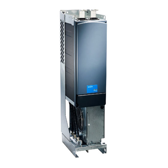
- Page 1 Design Guide DC Filters VACON® NXP DC/DC Converter drives.danfoss.com...
-
Page 3: Table Of Contents
DC Filter Selection, Air-cooling DC Filter Selection, Liquid-cooling Installation Guidelines Cabling Thermal Protection Mounting Maintenance Preventive Maintenance Recommendations Recommended Disposal Specifications General Specifications Environmental Data Cooling System Requirements Technical Data Dimensions Terminal and Torque Specifications Danfoss A/S © 2023.01 AJ377845348678en-000101/172F4785 | 3... -
Page 4: Introduction
• The operating and installation guides for VACON options give detailed information about specific drive options. ® Supplementary publications and manuals are available from Danfoss. See www.danfoss.com for listings. 1.3 Version History This design guide is regularly reviewed and updated. All suggestions for improvement are welcome. -
Page 5: Safety
DC filter. The Danfoss DC filter has been run through several demanding factory tests before the delivery. Carefully inspect the package for any damage that may have occurred during the transportation. Follow the instructions for unpacking the DC filter and carefully inspect it for any signs of possible damage. - Page 6 To reduce noise and EMI, and to prevent malfunctions in the installation, use shielded cables: Between the DC/DC converter output and DC filter input Between DC-filter output and Energy storage input 6 | Danfoss A/S © 2023.01 AJ377845348678en-000101 / 172F4785...
-
Page 7: Product Overview
Note: The type codes are for filter assemblies, which include three 1-phase inductors. For example, LDC-0092-5-0-APt consist of 3 x 92 A, 750 V DC inductors. Example The type code can have this format, for example: LDC-0092-5-0-APtX Table 2: Type Code Description Code Description Filter type Danfoss A/S © 2023.01 AJ377845348678en-000101 / 172F4785 | 7... - Page 8 5 = IP54 Cooling method A = Natural convection B = Forced air cooling C = Liquid cooling Temperature measurement type Pt = Pt100 temperature sensor Tr = Thermal relay Reserved for variants 8 | Danfoss A/S © 2023.01 AJ377845348678en-000101 / 172F4785...
-
Page 9: Selection
NXI_0520 5 < 613 FI12 NXI_0590 5 < 695 2 x LDC-0170-6-0-Axx 1180 2 x LDC-0270-5-0-Axx NXI_0650 5 < 766 1300 NXI_0730 5 < 870 1460 NXI_0820 5 < 977 1640 Danfoss A/S © 2023.01 AJ377845348678en-000101 / 172F4785 | 9... - Page 10 < 245 FI10 NXI_0261 6 < 308 LDC-0170-6-0-Axx LDC-0170-6-0-Axx NXI_0325 6 < 383 NXI_0385 6 < 454 NXI_0416 6 < 490 FI12 NXI_0460 6 < 548 2 x LDC-0092-6-0-Axx 2 x LDC-0170-6-0-Axx 10 | Danfoss A/S © 2023.01 AJ377845348678en-000101 / 172F4785...
-
Page 11: Dc Filter Selection, Liquid-Cooling
< 865 1460 CH63 NXP_0820 5 < 972 1640 NXP_0920 5 < 1090 LDC-0700-6-0-Cxx 1840 NXP_1030 5 < 1221 2060 NXP_1150 5 < 1378 2200 CH64 NXP_1370 5 < 1642 2740 LDC-1150-6-0-Cxx Danfoss A/S © 2023.01 AJ377845348678en-000101 / 172F4785 | 11... - Page 12 NXP_0920 6 < 1090 LDC-0700-6-0-Cxx 1840 NXP_1030 6 < 1221 2060 NXP_1180 6 < 1414 2360 LDC-1150-6-0-Cxx NXP_1300 6 < 1558 2600 NXP_1500 6 < 1798 3000 NXP_1700 6 < 2040 3400 12 | Danfoss A/S © 2023.01 AJ377845348678en-000101 / 172F4785...
-
Page 13: Installation Guidelines
Switching temperatures of the thermal relays depend on the DC filter type. See the datasheet of the DC filter for specific values. The temperature limits are: • Alarm = 125–140 °C • Fault = 140–155 °C Danfoss A/S © 2023.01 AJ377845348678en-000101 / 172F4785 | 13... -
Page 14: Mounting
Note: In any environment where vibration is present, mount the filters with top and bottom clamps for reliable installation. The distance from the cabinet walls to the inductors must be at least 20 mm. 14 | Danfoss A/S © 2023.01 AJ377845348678en-000101 / 172F4785... - Page 15 Note: If a forced air-cooled filter is used, the cooling fan or blower must be provided separately. See the specifications for the cooling system in 7.3 Cooling System Requirements. Illustration 6: DC Filter Mounting Example Air guides Airflow Danfoss A/S © 2023.01 AJ377845348678en-000101 / 172F4785 | 15...
-
Page 16: Maintenance
When the filter reaches the end of its service life, its primary components can be recycled. Contact your local Danfoss office for further information on environmental aspects and recycling instructions for professional recy- clers. End of life treatment must follow international and local regulations. -
Page 17: Specifications
PD 3 Air quality Chemically active substances: 3C2 Contamination levels (IEC 60721-3-3) Mechanically active substances: 3S2 Altitude (during operation) Maximum 2000 m above sea level. Current derating according to equivalent DC/DC converter. Danfoss A/S © 2023.01 AJ377845348678en-000101 / 172F4785 | 17... -
Page 18: Cooling System Requirements
[V DC] at 50 °C 20 °C rating [kHz] 181B5954 LDC-0010-6-0-APt 40277-SET-PT100 1025 IP00 181B5955 LDC-0010-6-0-ATr 40277-SET-THER- 181B5956 LDC-0020-5-0-APt 40260-SET-PT100 IP00 181B5957 LDC-0020-5-0-ATr 40260-SET-THER- 181B5958 LDC-0030-6-0-APt 56606-SET-PT100 1025 IP00 18 | Danfoss A/S © 2023.01 AJ377845348678en-000101 / 172F4785... - Page 19 38349-SET-PT100 1025 1100 IP00 181B5979 LDC-0400-6-0-BTr 38349-SET-THER- 181B5980 LDC-0420-5-0-APt 39023-SET-PT100 IP00 181B5981 LDC-0420-5-0-ATr 39023-SET-THER- 181B5982 LDC-0540-6-0-BPt 44079-SET-PT100 1025 1300 IP00 181B5983 LDC-0540-6-0-BTr 44079-SET-THER- 181B5986 LDC-0900-5-0-BPt 53552-SET-PT100 1900 IP00 181B5987 LDC-0900-5-0-BTr 53552-SET-THER- Danfoss A/S © 2023.01 AJ377845348678en-000101 / 172F4785 | 19...
-
Page 20: Dimensions
154±2 329±5 7x14 – LDC-0020-5-0-ATr LDC-0030-6-0-APt 158±5 299±3 7x14 – LDC-0030-6-0-ATr LDC-0050-6-0-APt Illustration 8 260±5 139±5 271±3 – LDC-0050-6-0-ATr LDC-0092-5-0-APt 303±10 161±5 269±5 – LDC-0092-5-0-ATr LDC-0092-6-0-APt 305±5 168±3 339±5 – LDC-0092-6-0-ATr 20 | Danfoss A/S © 2023.01 AJ377845348678en-000101 / 172F4785... - Page 21 LDC-0540-6-0-BTr LDC-0900-5-0-BPt 276±10 240±5 484±5 11x16 – LDC-0900-5-0-BTr LDC-0160-6-0-CPt Illustration 9 345±5 213±10 397±5 LDC-0160-6-0-CTr LDC-0340-6-0-CPt 406±5 200±4 447±5 LDC-0340-6-0-CTr LDC-0700-6-0-CPt 466±5 231±5 503±5 170±3 LDC-0700-6-0-CTr LDC-1150-6-0-CPt 466±5 260±5 557±5 LDC-1150-6-0-CTr Danfoss A/S © 2023.01 AJ377845348678en-000101 / 172F4785 | 21...
- Page 22 DC Filters Design Guide Specifications Illustration 7: Dimensions of the Air-cooled Inductors, 10–30 A Illustration 8: Dimensions of the Air-cooled Inductors, >30 A 22 | Danfoss A/S © 2023.01 AJ377845348678en-000101 / 172F4785...
-
Page 23: Terminal And Torque Specifications
Base LDC-0420-5-0-Axx Busbar 1 x D13, M12 Base LDC-0540-6-0-Bxx Busbar 1 x D13, M12 Base LDC-0900-5-0-Bxx Busbar 2 x D13, 2 x M12 Base LDC-0160-6-0-Cxx Busbar 1 x D9, M8 Base Danfoss A/S © 2023.01 AJ377845348678en-000101 / 172F4785 | 23... - Page 24 Design Guide Specifications Filter type code Connection size Connection Torque [Nm] Mounting location Terminal Grounding Terminal Grounding LDC-0340-6-0-Cxx Busbar D(13x20), M12 Base LDC-0700-6-0-Cxx Busbar D(13x20), M12 Base LDC-1150-6-0-Cxx Busbar D(13x20), M12 Base 24 | Danfoss A/S © 2023.01 AJ377845348678en-000101 / 172F4785...
- Page 25 Current range....................7 Safety........................5 Selection......................9 Dimensions.....................20 Specifications....................17 Disposal.....................16, 16 Symbols......................5 Environment....................17 Technical data....................18 Terminals......................23 Thermal protection..................13 Filter types......................7 Tightening torques..................23 Type code......................7 Liquid cooling....................18 Version history....................4 Voltage range....................7 Maintenance....................16 Mounting......................14 Danfoss A/S © 2023.01 AJ377845348678en-000101/172F4785 | 25...
- Page 26 Danfoss can accept no responsibility for possible errors in catalogs, brochures and other printed material. Danfoss reserves the right to alter its products without notice. This also applies to products already on order provided that such alterations can be made without subsequential changes being necessary in specifications already agreed. All trademarks in this material are property of the respective companies.
Need help?
Do you have a question about the VACON NXP and is the answer not in the manual?
Questions and answers