Table of Contents
Advertisement
Quick Links
Service Manual_2022-V2.0
Service Manual
French-Door Series
Applicable Models
Product Models
Applicable Models
HQ-827WEN
UR-BCD636WE-ST
22031040001341
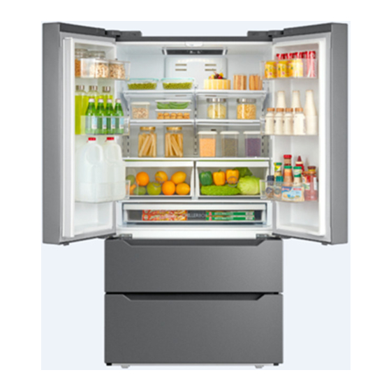
The picture in this service manual is only for reference, and specific appearance
and configuration are subject to the real product.
This manual mainly teaches the method, the specific work skill needs engineer
to accumulate through the daily work.
1
Advertisement
Table of Contents

Related Manuals for Midea HQ-827WEN


Summary of Contents for Midea HQ-827WEN
- Page 1 Service Manual French-Door Series Applicable Models Product Models Applicable Models HQ-827WEN UR-BCD636WE-ST 22031040001341 The picture in this service manual is only for reference, and specific appearance and configuration are subject to the real product. This manual mainly teaches the method, the specific work skill needs engineer...
- Page 2 Manufacturers or distributors are not responsible for the content of the Manual and interpretation thereof. Midea Refrigerators Technical Maintenance Manual Copyright @2017 All rights reserved. Replication of all or part of the Manual in any forms shall not be allowed without written approval by the Overseas Sales Corporation of Midea Refrigerators.
-
Page 3: Table Of Contents
Service Manual_2022-V2.0 Contents SIGNIFICANT UPDATE NOTES (NONE) ......................5 2. SAFETY WARNING ............................... 6 2.1 W ........................... 6 ARNING FOR OPERATION SAFETY ......................... 8 2.2 S AFETY INSTRUCTION FOR REFRIGERANT 3. INSTALLATION AND COMMISSIONING ......................9 ................................... 9 3.1 H ANDLING 3.2 D ........................ - Page 4 Service Manual_2022-V2.0 7.11 W ............................... 43 ATERWAY SYSTEM 8. TEMPERATURE SENSING SYSTEM ......................... 44 ............................44 8.1 P OSITION OF SENSORS ........................... 44 8.2 R EPLACEMENT OF SENSORS 8.3 S ......................45 ENSOR WITHOUT TERMINAL REPLACEMENT ..............................46 8.4 S ENSOR TABLE 9.
-
Page 5: Significant Update Notes (None)
Service Manual_2022-V2.0 1. Significant update notes (None) -
Page 6: Safety Warning
Service Manual_2022-V2.0 2. Safety Warning 2.1 Warning for operation safety Important Safety Instructions CAUTION RISK OF ELECTRIC SHOCK DO NOT OPEN This symbol indicates that dangerous voltage constituting a risk of electric shock is present within your freezer. This symbol indicates that there are important operating and maintenance instructions in the literature accompanying your freezer. - Page 7 Service Manual_2022-V2.0 CONNECTING ELECTRICITY Electrical Shock Hazard. Failure to follow these instructions can Plug into a grounded 3-prong outlet. result in death, fire, or electrical shock. Do not remove the ground prong. Do not use an adapter. WARNING Electric Shock Hazard Failure to follow these instructions can result in electric shock, fire, or death.
-
Page 8: Safety Instruction For Refrigerant
Service Manual_2022-V2.0 13) Do not store or use gasoline or any flammable liquids inside or in the vicinity of this freezer. 14) Do not use extension cords or ungrounded (two-prong) adapters with this freezer. If the power cord is too short, have a qualified electrician install an outlet near the freezer. Use of an extension cord can negatively affect the freezer’s performance. -
Page 9: Installation And Commissioning
Service Manual_2022-V2.0 3. Installation and commissioning 3.1 Handling Handling Protect the refrigerator in moving it,Same as shown as left photo, please move it by handcart with cushion Remove all packing materials and bottom cushion, the move into house for placement After moving it to appropriate location, wait for 2 hou rs before power on. - Page 10 Service Manual_2022-V2.0 3) Take down the left (right) hinge. 4) Uplift the right/left cooler door and take it down from the left (right) middle hinge; Disassembly and assembly of freezer door and annex 1) open the refrigerator doors, and pull the freezer drawer outwards to the end, then incline the inside drawer liner at an angle and take it out;...
-
Page 11: Installation Location
Service Manual_2022-V2.0 4)Place the upper freezer drawer on ground as the way shown in the right picture; 5)Separate the metal connection lever by pull the guide rail to the opposite direction; 6)Push the gear slantingly as shown in right picture, and separate the gear from the guide rail. -
Page 12: Leveling Of The Refrigerator
Service Manual_2022-V2.0 When the refrigerator is placed in the cabinet (Counter-depth), you can reserve space according to the recommended size shown in the picture, but there should be a large enough vent at the top and bottom of the cabinet to allow air flow. It is recommended to install an exhaust fan. -
Page 13: Adjustment To Level The Door
Service Manual_2022-V2.0 1)Take out the bolts for fixing the handle from the package bag of the user manual and then fasten it on the door body with a cross screwdriver 2)Take out the door handle from the refrigerating chamber, and place it in the two handle fixed bolts in the direction as shown in the attached diagram 3)Use the allen wrench to fasten the screws in two holes of each handle with the handle fixing bolts... - Page 14 Service Manual_2022-V2.0 Adjustment to in homogenous aperture the door (Up and down) Use screwdriver to remove the 2 pcs screws, and then remove the upper hinge cover. Use screwdriver to loosen the 2 pcs screws, right and left adjust the upper hinge to make door aperture be homogeneity.
-
Page 15: Main Parts And External Dimension
Service Manual_2022-V2.0 4. Main parts and external dimension 4.1 Main parts (The picture is only for reference, and specific appearance and configuration are subject to the real product) Refrigerator chamber Freezer chamber... -
Page 16: External Dimension
Service Manual_2022-V2.0 4.2 External dimension Description Code Size (mm) Size (in) Height to Top of Case 1775 69.88 Width 35.98 Depth w / No handle 29.02 Depth w / Handle 31.30 Depth w / No door 24.61 Depth (Door open 90 deg. w) 1097 43.19 Width (Door open 90 deg. -
Page 17: Midea Product Serial Number And Location
Service Manual_2022-V2.0 4.3 Midea product serial number and location 1) Product Serial Number — Including order number, production date and other information. When the product occur problem, it needs to be recorded or photographed and provided to us. 2)Paste location... -
Page 18: Electric Control System
Service Manual_2022-V2.0 5. Electric control system 5.1 Electrical parts parameters Applicable Model HQ-827WEN Product Model UR-BCD636WE-ST 115V 、60Hz Rated Voltage Item Specification R600a Refrigerant TRA100E23DAH Compressor (Part code : 11101020001442) DC Inverter Starting device type The COP of compressor 2.00 (W/W) - Page 19 Service Manual_2022-V2.0 Water valve 220-240V 20W Electric exchange valve None Power filter (EMI) 250V、4A Power reactor (EU EMC) 115/230V、3A Defrosting and heating parts NTC B3839 ( B5/25=3839K± 2% ) Defrosting sensor AC250V/10A、77(0,-4) ℃ Fuse in freezing chamber Defrost heater in freezing chamber AC230V、190W Flipping beam heating wire AC220V、11W...
-
Page 20: Circuit Diagram
Service Manual_2022-V2.0 5.2 Circuit diagram F: Freezer R: Refrigerator Def: Defrost T-H: Temperature and humidity RM: Refrigerator fan motor FM: Freezer fan motor... -
Page 21: Main Pcb Terminal Connection Diagram
Service Manual_2022-V2.0 5.3 Main PCB terminal connection diagram Name of Connecting terminals Name of Connecting terminals 1. Power 12. Condensate fan 2.Freezing defrost heater 13. display control panel 3.Water valve 14. Variable frequency driver board 4. Flipping beam heating wire Temperature sensor 5. -
Page 22: Inverter Board Terminal Connection Diagram(Option
Service Manual_2022-V2.0 5.4 Inverter board terminal connection diagram(Option)... -
Page 23: Refrigeration System
Service Manual_2022-V2.0 6. Refrigeration system 6.1 Refrigeration system working principle ❶Compressor→❷Condenser→❸Anti-condensation tube→❹Dry filter→❺Capillary tube→ ❻Evaporator→❼Suction tube→❽Compressor 6.2 Cooling pipeline and drain pipe inside the cabinet... -
Page 24: Circulating Route Of Cooling Air
Service Manual_2022-V2.0 6.3 Circulating route of cooling air 6.4 Welding points in chambers or foam layer Welding points on freezer evaporator Welding point Pipe outer diameter (mm) 1-Freezer capillary and inlet of evaporator Copper pipe: Copper pipe: Φ6.5 Φ6.35 2-Heat transition tube and outlet of evaporator Copper pipe: Copper pipe: Φ6.5 Φ6.35... -
Page 25: Welding Point In The Compressor Case
Service Manual_2022-V2.0 6.5 Welding point in the compressor case Welding point location (mm) Pipe outer diameter (mm) 1-Compressor outlet tube and inlet of condenser :Copper pipe: Steel pipe: Φ4.96 Φ4.76 Steel pipe: Φ4.0 Copper pipe: Φ4.2 2- Inlet of anti-condensation tube and outlet of condenser Steel pipe: Φ4.0 Steel pipe: Φ4.2 3-Outlet of anti-condensation tube and inlet of dry filter... -
Page 26: Dismantling Of Parts
Service Manual_2022-V2.0 7. Dismantling of parts 7.1 Parts on the door Door gasket Door gasket is installed into door liner groove. 1) Open the refrigerator door; 2) Take the Door gasket ①out of door liner. Door tray While squeezing it inward, lift up the baffle and take it out from refrigerator liner. - Page 27 Service Manual_2022-V2.0 pull out the whole rollover beam to separate the lower part from the door; Unplug the wire terminal, remove the rollover beam, resverse the operation to complete the installation. Door self-locking and stopper After removing the refrigeration door, remove the fixing screws, then remove the door self-locking and stopper, and complete the replacement.
- Page 28 Service Manual_2022-V2.0 Disassembly and assembly of freezer door and accessories Open the refrigerator doors, and pull the freezer drawer outwards to the end, then incline the inside drawer liner at an angle and take it out Press down left and right button of bracket Continue to pull drawer outwards so as to separate the metal guide rail Place the upper freezer drawer on ground as the...
-
Page 29: Parts Inside The Refrigerator
Service Manual_2022-V2.0 Push the gear slantingly as shown in right picture, and separate the gear from the guide rail. 7.2 Parts inside the refrigerator Shelves 1) Hold the front edge of glass shelf by uplift by certain angle; 2) Uplift the glass shelf ,and separate it from the shelf; 3)Take out the shelf horizontally. -
Page 30: Light System
Service Manual_2022-V2.0 Fruits and vegetables box and cover 1) Hold the handle and pull outwards the fruits and vegetables box to the most extent 2) Lift it up, separate it from the guide. 3) Then lift up the cover, and pull out it. 7.3 Light system Light Light of the refrigerating... - Page 31 Service Manual_2022-V2.0 Light of the freezing 1) Remove lamp cover 2) Disconnect the connector terminal and remove LED lamp. Light switch There is a pillar switch on each hinge cover of left and right doors of the refrigerator. 1) Remove bolts of hinge cover with a cross screwdriver 2)...
-
Page 32: Air Duct Components Refrigerating Chamber And Fan Motor
Service Manual_2022-V2.0 7.4 Air duct components refrigerating chamber and fan motor Refrigerator air duct assembly All accessories in the refrigerating chamber should be removed before dismantling the air duct assembly. 2) Remove 4 fixed screw with a cross screwdriver after removing the white decorative cap on the surface of the air duct Dismantle the supporting iron bar in the middle of refrigerator air duct cover... -
Page 33: Ice Maker
Service Manual_2022-V2.0 Damper assembly Take out the electric damper assembly, remove the wiring terminal, and replace it with a new one. 7.5 Ice maker disassembly of ice maker the ice maker is fixed on the top liner of freezer room by means of hanging button, pull the ice maker outwards and along the horizontal direction, so as to separate it from the hanging button... -
Page 34: Air Duct Components In Freezing Chamber And Fan Motor
Service Manual_2022-V2.0 7.6 Air duct components in freezing chamber and fan motor Air duct assembly in freezing chamber 1) Use cross screwdriver to rotate anticlockwise, for remove the 4 pcs screws; 2) Dismantle the air duct cover outwards; 3) pull out the fan motor and temperature sensor plug-in terminal at the upper right corner. -
Page 35: Evaporator And Defrost System
Service Manual_2022-V2.0 3) Use cross screwdriver to remove the 3 pcs screws of fan motor 4) Replace the fan in reverse steps. 7.7 Evaporator and Defrost system Evaporator in freezing chamber 1) Remove the air duct components in freezing chamber. 2)... -
Page 36: Compressor Case
Service Manual_2022-V2.0 7.8 Compressor case Rear cover 1)Remove by cross screwdriver the screws fixing back cover plate of compressor chamber anticlockwise; 2)Take the back cover plate of compressor chamber upward. Piping system in the compressor case 1-Suction connection tube 5-Water tray 2-Dry filter 6-Circumflex fin condenser 3-Constant speed reciprocating compressors... - Page 37 Service Manual_2022-V2.0 3) Cut off the compressor pipeline.-❶Cut off the process pipeline.-❷Cut off the low-pressure muffler.-❸Cut off the high-pressure exhaust pipe. 4-1)Remove the screws(for some models) -One screws outside -One screw inside 4-2)Remove the metal clamp(for some models) -Disassembly the metal clamp that is fix the electric appliance shield 5)Remove the clipping strip Slowly pull it out...
- Page 38 Service Manual_2022-V2.0 7)Remove the protector Unplug the protector (you can use a screwdriver to pry it slowly) 8)Loosen the screw of the compressor bottom plate, remove the floor together with the compressor from the box. 9)Use the wrench to remove the bolts by steps❹❺❻❼, replace the compressor and reverse process can complete installation.
- Page 39 Service Manual_2022-V2.0 11) Replace the compressor and welding the compressor pipeline.-❿Welding the process pipeline.-⓫Welding the low-pressure muffler.-⓬Welding the high-pressure exhaust pipe. 12)Replace the filter, Cu-Fe tubes welding ⓭ used Ag welding rod, Cu-Cu tubes welding ⓮ used Cu welding rod. 13)Vacuum system, the degree of vacuum below 6Pa.
- Page 40 Service Manual_2022-V2.0 Condenser fan motor 1) unplug the wiring connector of condenser fan motor; 2) use screwdriver to pry up the bottom, meanwhile pull it outwards; 3) dismantle the condenser fan motor from the base. Drain tray 1)Remove the bottom screws of the compressor bottom plate...
-
Page 41: Display Control Board
Service Manual_2022-V2.0 2)Replace the drain tray, the reverse process can complete installation. 7.11 Display control board Display control board and refrigerator top light 1. Control panel with cross screw driver; 2. Detach the roof display and control panel to remove the ceiling lamp and display and control PCB board terminal;... -
Page 42: Main Control Board
Service Manual_2022-V2.0 6. Remove the fastener around the transparent cover of display and control panel with straight screwdriver and take off the transparent cover; 7. Push aside the fastener around LED light panel and detach the LED light panel. 7.10 Main control board Have variable frequency driver board The main PCB and inverter are placed on rear side of cabinet... -
Page 43: Waterway System
Service Manual_2022-V2.0 7.11 Waterway system You need a suitable adapter for connecting the water pipe with the water tap. The water pipe must be a 1/4in size hose. As shown on the right. 1) Please insert the water pipe(14) into one end of adapter(13);... -
Page 44: Temperature Sensing System
Service Manual_2022-V2.0 8. Temperature sensing system 8.1 Position of sensors Position of sensors Have 4 sensors ① Temperature Sensor in freezing chamber ② Temperature Sensor in refrigerating chamber ④ Ambient humidity sensor ⑦ Defrost sensor in freezing chamber 8.2 Replacement of sensors Sensor in freezing chamber All air duct components in the freezing chamber should be dismantled before removing the temperature sensor... -
Page 45: Sensor Without Terminal Replacement
Service Manual_2022-V2.0 Sensor in refrigerating chamber The air duct components in refrigerating chamber should be dismantled before removing the sensor. 1) Remove the air duct components in refrigerating chamber; 2) Remove the sensor. Ambient temperature sensor The sensors is located in the upper hinge cover of the refrigerator right door, it sends a temperature and humidity signal to the microprocessor. -
Page 46: Sensor R/Ttable
Take out a new sensor to cut the head of sensor. (Spare parts code:11201007000795) Its technical specifications apply to all MIDEA refrigerators. Strip off the head of the sensor and connect it. Wrap the two wires together with insulation tape. - Page 47 Service Manual_2022-V2.0 21.18 9.316 4.372 2.188 1.161 20.01 8.841 4.167 2.094 1.115 18.9 8.392 3.972 2.005 1.071 17.87 7.968 3.788 1.919 1.029 16.9 7.568 3.613 1.838 0.9885 15.98 7.19 3.447 1.761 0.9506 15.12 6.833 3.29 1.687 0.914...
-
Page 48: Function And Operation
Service Manual_2022-V2.0 9. Function and operation 9.1 Display operation panel Ice maker mode Super cool mode setting button Refrigeration temperature adjustment button Refrigeration Temp display area Freezing Temp display area Freezing temperature adjustment button Super freeze mode setting button Lock and unlock button 9.2 Temperature control 9.2.1 Refrigerator temperature setting 1、Regulate the set temperature of refrigerating chamber, the setting range of refrigerating chamber... -
Page 49: Defrosting Function
Note: When open the door, the display panel is light on; when the door is closed, the display panel will be light off after 30s if there is no any operation on display panel 9.6 Fault code and solutions Note: midea full common fault code, combined with the actual product display reference Fault code Fault content... - Page 50 Service Manual_2022-V2.0 Step 3: Inspect the refrigerating sensor whether contact is bad, and resend contact the fast connector Step 4: Replace main control board Step 1: Check whether the terminal of temperature sensor in main control board is welll stuck, pull out the terminal and re-stick it in place Step 2: Check to see if there’re foreign matters on the terminal.
-
Page 51: Test Mode
Service Manual_2022-V2.0 9.7 Test mode Test items Testing Method Expected result Keep pressing the “LOCK” and LED indicators display “0”, then the refrigerator “SUPER COOL” button for 5 enters into test mode Enter Test seconds and release Mode After entering into test mode, if no then the refrigerator will exit the test mode and button is pressed within 30 return to normal operation mode... -
Page 52: Demo Mode
Service Manual_2022-V2.0 4)Load:Ice maker component check, after the ice maker turn over the ice once and until the Ice-probing rod move to level position, stop movement, water pump on 2 seconds . Water valve: water valve on 2 seconds 5) Exit:Load action finished will exit ice maker test mode. If check ice storage box is full with ice or ice making operation is fault, will exit Ice maker test mode. -
Page 53: Compressor
Service Manual_2022-V2.0 10. Compressor 10.1 Compressor on and off control specifications Compressor on and off control: 1.1 When one of the following conditions is met, the compressor stops: 1) Tr ≤ Trt; 2) The compressor runs continuously for more than 3 hours (Stop 5 minutes); 1.2 When all the following conditions are met, the compressor starts up: 1) Tr ≥Trk;... -
Page 54: Troubleshooting Method
Service Manual_2022-V2.0 11. Troubleshooting Method 11.1 No cooling (Air cooling-Electronic) -
Page 55: No Working Of Compressor
Service Manual_2022-V2.0 11.2 No working of compressor 11.3 Inside frosting, no defrosting... -
Page 56: Inside Frosting, No Defrosting-Maintenance Guidelines
Service Manual_2022-V2.0 11.4 Inside frosting, no defrosting-Maintenance guidelines... -
Page 57: Light Is Not On
Service Manual_2022-V2.0 11.5 Light is not on 11.6 Fan failure... -
Page 58: Defective Defrost Circuit
Service Manual_2022-V2.0 11.7 Defective defrost circuit 11.8 Noise... -
Page 59: Air Duct Not Operated (Electronically)
Service Manual_2022-V2.0 11.9 Air duct not operated (electronically) 11.10 ice maker not make ice Press both “LOCK/UNLOCK” button and “FRZ.TEMP.” button together for 3 seconds, then you can set up or cancel the mandatory mode. After the mandatory mode is effective, press “FRZ.TEMP.” button, the temperature of the freezer will show a circulation of “0”, “1”, “3”... -
Page 60: Product Exploded View And Spare Parts List
Service Manual_2022-V2.0 12. Product exploded view and spare parts list Please log in to TSP system to view and download these contents. - Page 61 For more information about where you can drop off your waste for recycling, please contact your local authority, or where you purchased your product. Midea Refrigerators If you need to get detailed technical information from the manufacturer, please contact: xxx@midea.com...
Need help?
Do you have a question about the HQ-827WEN and is the answer not in the manual?
Questions and answers