Table of Contents
Advertisement
Quick Links
Advertisement
Table of Contents

Subscribe to Our Youtube Channel
Related Manuals for A&D FG-D-CWP


Summary of Contents for A&D FG-D-CWP
- Page 1 FG-D-CWP Weighing Indicator For Waterproof Digital Platform Scale 1WMPD4004854...
- Page 2 This Manual and Marks All safety messages are identified by the following, “WARNING” or “CAUTION”, of ANSI Z535.4 (American National Standard Institute: Product Safety Signs and Labels). The meanings are as follows: A potentially hazardous situation which, if not avoided, could WARNING result in death or serious injury.
-
Page 3: Table Of Contents
Contents 1. COMPLIANCE ............................4 1.1......................4 OMPLIANCE WITH RULES 1.2.............. 4 LASSIFICATION OF ROTECTION ROVIDED BY NCLOSURES 2. INTRODUCTION ............................. 5 3. OUTLINE AND FEATURES ........................5 4. ITEMS INCLUDED ........................... 6 5. INSTALLATION AND PRECAUTIONS ....................7 5.1. -
Page 4: Compliance
1. Compliance 1.1. Compliance with FCC rules Please note that this equipment generates, uses and can radiate radio frequency energy. This equipment has been tested and has been found to comply with the limits of a Class A computing device pursuant to Subpart J of Part 15 of FCC rules. These rules are designed to provide reasonable protection against interference when this equipment is operated in a commercial environment. -
Page 5: Introduction
This instruction manual mainly describes installation. Please refer to it when connecting or installing the FG-D-CWP to a weighing platform (load cell). Also, the FG-D-CWP has the same functions as that of the indicator for the FG-CWP series. Although this manual covers some of the functions and how to use the series, the following instruction manual explains all of them. -
Page 6: Items Included
4. Items Included The following items are packed with the product. FG-D-CWP Model label (1083039230-1) Indicator Attach here Write the scale’s ratings, etc. Quick start guide AC adapter Rubber packing (To be used when the diameter of load cell cable is from φ3.5 to φ7.0) FG-D-CWP (This document is included in the packing contents for the balance.) -
Page 7: Installation And Precautions
5.2. Load Cell Connection FG-D-CWP has two connection configurations: the 6-wire configuration and the 4-wire configuration. We recommend connecting using the 6-wire configuration for optimum accuracy and stability. The applicable diameter of load cell cable is from φ3.5 to φ9.0 mm. - Page 8 Load cell Cable Cable Load cell input (-) Load cell input (+) Load cell excitation voltage (-) Sensing input (-) Sensing input (+) Load cell excitation voltage (+) Shield Shield (A) 6-wire configuration connection (B) 4-wire configuration to load cell (recommended) connection to load cell Method Advantage...
-
Page 9: How To Connect The Load Cell
5.3. How to Connect the Load Cell Disconnect the power cable of the scale (indicator) from the plug. Remove the 4 M3 screws from the load cell panel on the backside of the indicator, and open the load cell panel. Load cell panel Loosen the lock of the cable clamp connecting Load cell cable... -
Page 10: Verifying Load Cell Output And Input Sensitivity
0.1 ≤ d: Minimum division A x n E: Excitation voltage (mV) = 5000 mV for FG-D-CWP n: Number of load cells Example of calculation: In the case of designing a scale with a capacity of 60 kg and minimum division of 0.005 kg, using one load... -
Page 11: Setting Up The Indicator
5.5. Setting Up the Indicator 1. Insert the USB plug into the AC adapter included with this product and connect it to the power supply. □ Confirm that local voltage and receptacle type are correct. □ You can also use except for the AC adapter included with this product. This product can also be powered from a USB port or mobile battery. -
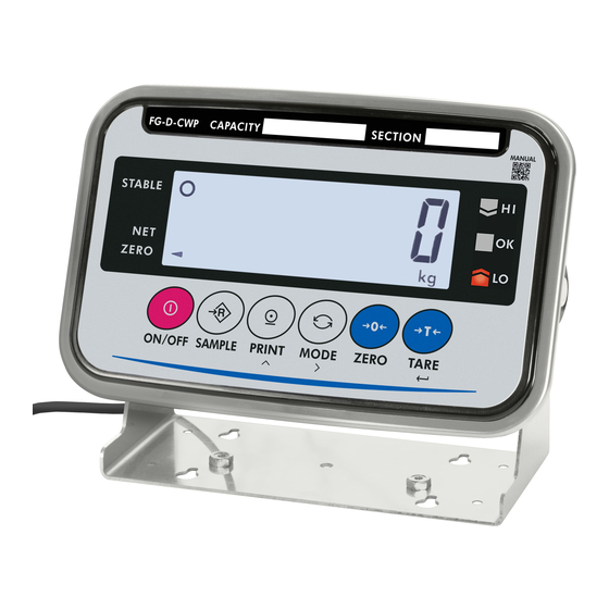
Page 12: Part Names
6. Part Names Display unit knob Display Unit (SUS304) Serial Number Load Cell Panel Load Cell Connector USB Plug USB Cable (Approx. 3 m) 6.1. Display and Symbols Display Unit Weighing Condition Comparator Conditions for Weighing Each Function Units Display/symbol Description This is lit when the weighing value is stable, indicating that the scale is in the STABLE... -
Page 13: Operation Keys
This is a function to detect impact to the mass sensor section and to display the impact level. Turns on when the connection with the wireless communication receiver is established. While the comparator function is being used, the weighing value is compared using the preset threshold values and the indicator displays the result. -
Page 14: Sensitivity Adjustment
7. Sensitivity Adjustment The description of sensitivity adjustment in this manual is different from that in the instruction manual for the FG-CWP series. Please read the description below. 7.1. Sensitivity Adjustment Items Sensitivity adjustment mode has the following three functions. Setting of the weighing capacity, minimum division, and decimal point position. - Page 15 Relations between items in sensitivity adjustment mode and key operations are shown in the diagram below. Weighing mode Method 1 Method 2 Press and hold Press In sensitivity adjustment mode (transition method) Press Setting of the weighing capacity, minimum division, and decimal point Press Press Sensitivity adjustment using a weight...
-
Page 16: Setting Of The Weighing Capacity / Minimum Division / Decimal Point Position
7.2. Setting of the Weighing Capacity / Minimum Division / Decimal Point Position Set the weighing capacity, minimum division, and decimal point position. Be sure to perform these setting first when connecting to a load cell (base unit). The indicator does not require setting each time, if nothing is to be changed. -
Page 17: Sensitivity Adjustment Using A Weight
7.3. Sensitivity Adjustment Using a Weight This function adjusts the scale (indicator) for accurate weighing. Sensitivity adjustment must be done when the FG-D-CWP is initially connected to a load cell (base unit) or the combination is changed. Sensitivity adjustment may also be required according the changes in the environment. -
Page 18: Correcting For Gravitational Acceleration
7. Place on the weighing pan a weight of the value displayed. Wait for the stability indicator to light up. 8. Press the TARE key to end sensitivity adjustment. will be displayed. After displaying , the setting is complete. 9. To end setting, press the ZERO key or CAL key. -
Page 19: Setting Functions Or Units For Use
Setting Functions or Units for Use The indicator has CF function settings to specify the indicator performance. After installing the indicator, the indicator does not require resetting or changing of this CF function as far as it is used normally. If you want to maintain only the needed units, set using this function. The parameters set in the CF function settings and unit setting are maintained even if the power is turned OFF. -
Page 20: Setting Units For Use
8.2. Setting Units for Use 1. Refer to “7.1. Sensitivity Adjustment Items”, to enter the sensitivity adjustment mode. The indicator displays Press 3 times 2. Press the MODE key three times to display 3. Press the TARE key to display the setting item. Press 4. -
Page 21: Cf Function List
8.3. CF Function List Item Parameter Description Used internally Not available for setting change Used internally Not available for setting change When Not available for setting of function Zero tracking (It is fixed to has no function. Available for setting of function Power on zero range None Calibration zero... -
Page 22: Options
Item Parameter Description Used internally Not available for setting change Saving zero value Saves zero value Do not save and tare weight and tare weight even after the Save power turns off. Display limit of “ ” Weighing capacity + 8d Weighing capacity + 8d + (capacity/30) Weighing capacity + 8d + (capacity/15) Weighing capacity + 8d + (capacity/6) -
Page 23: Maintenance
10. Maintenance Refer to “5. Installation and Precautions” regarding use. Refer to “10.3. Error Code Table” and corresponding mode for displayed error code. Refer to “7. Sensitivity Adjustment” regarding precision weighing. Periodically check the accuracy of weighing. Adjust the scale (indicator), if it is moved to another location or the environment has changed. -
Page 24: Error Code Table
10.3. Error Code Table When any of the following errors are displayed, try turning the display off and on again. Display Content is displayed The temperature sensor has failed. is displayed The memory (circuit) has failed. is displayed The internal circuitry has failed. is displayed The mass sensor has failed. -
Page 25: Specifications
11. Specifications 11.1. Specifications List Specifications are subject to change without notice. Input sensitivity 0.1 μV/d min. (d: minimum division) Input signal range -16 mV to 16 mV Load cell excitation voltage 5 V ± 10 % Load cell drive capacity Up to 4 x 350 ohm loadcells Temperature coefficient Zero ±0.02 μV/°C typ. -
Page 26: Dimensions
11.2. Dimensions FG-D-CWP Unit: mm... -
Page 27: Gravity Acceleration Map
11.3. Gravity Acceleration Map Values of gravity at various locations Amsterdam 9.813 m/s Manila 9.784 m/s Athens 9.800 m/s Melbourne 9.800 m/s Auckland NZ 9.799 m/s Mexico City 9.786 m/s Bangkok 9.783 m/s Milan 9.807 m/s Birmingham 9.813 m/s Moscow 9.816 m/s Brussels 9.811 m/s... - Page 28 1. Back cover: A&D Global A&D Company, Limited 3-23-14 Higashi-Ikebukuro, Toshima-ku, Tokyo 170-0013, JAPAN Telephone: [81] (3) 5391-6132 Fax: [81] (3) 5391-1566 A&D ENGINEERING, INC. 47747 Warm Springs Blvd, Fremont, California 94539, U.S.A. Tel: [1] (800) 726-3364 Weighing Support:[1] (888) 726-5931 Inspection Support:[1] (855) 332-8815 A&D INSTRUMENTS LIMITED Unit 24/26 Blacklands Way, Abingdon Business Park, Abingdon, Oxfordshire OX14 1DY United Kingdom...
Need help?
Do you have a question about the FG-D-CWP and is the answer not in the manual?
Questions and answers