
Related Manuals for Samson EB 8315 EN


Summary of Contents for Samson EB 8315 EN
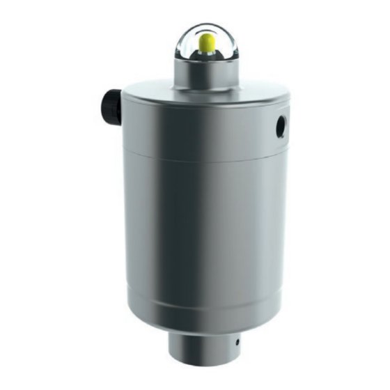
- Page 1 EB 8315 EN Translation of original instructions Type 3379 Pneumatic Actuator Edition September 2022...
- Page 2 Note on these mounting and operating instructions These mounting and operating instructions assist you in mounting and operating the device safely. The instructions are binding for handling SAMSON devices. The images shown in these instructions are for illustration purposes only. The actual product may vary.
-
Page 3: Table Of Contents
Troubleshooting ..................8-1 Emergency action ..................8-1 Servicing and conversion ................9-1 Periodic testing ...................9-2 Preparation for servicing or conversion work ..........9-2 Exchanging the actuator bonnet ..............9-2 9.3.1 Removing the cover ..................9-2 9.3.2 Removing the Type 4740 Limit Switch ............9-2 EB 8315 EN... - Page 4 Mounting the bonnet ...................9-2 Ordering spare parts and operating supplies ..........9-4 Decommissioning ..................10-1 Removal ....................11-1 11.1 Removing the actuator from the valve ............11-1 Repairs ....................12-1 12.1 Returning devices to SAMSON ..............12-1 Disposal ....................13-1 Annex......................14-1 14.1 After-sales service ..................14-1 EB 8315 EN...
-
Page 5: Safety Instructions And Measures
SAMSON. SAMSON does not assume any liability for damage resulting from the failure to use the de- vice for its intended purpose or for damage caused by external forces or any other external factors. - Page 6 Î Check with the plant operator for details on further protective equipment. Revisions and other modifications Revisions, conversions or other modifications of the product are not authorized by SAMSON. They are performed at the user's own risk and may lead to safety hazards, for example. Fur- thermore, the product may no longer meet the requirements for its intended use.
- Page 7 The following documents apply in addition to these mounting and operating instructions: − Mounting and operating instructions for the valve on which it is mounted − Mounting and operating instructions for mounted valve accessories (positioner, solenoid valve etc.) EB 8315 EN...
-
Page 8: Notes On Possible Severe Personal Injury
Î Wear eye and hearing protection when working near the actuator. If not described otherwise in the valve documentation, the work position for the control valve is the front view looking onto the operating controls (including valve accessories). EB 8315 EN... -
Page 9: Notes On Possible Property Damage
Parts that are not tightened far enough may loosen. Î Observe the specified tightening torques. Risk of actuator damage due to the use of unsuitable tools. Certain tools are required to work on the actuator. Î Only use tools approved by SAMSON. EB 8315 EN... -
Page 10: Warnings On The Device
Risk of actuator damage due to the use of unsuitable lubricants. The lubricants to be used depend on the actuator material. Unsuitable lubricants may corrode and damage surfaces. Î Only use lubricants approved by SAMSON. 1.4 Warnings on the device Warning... -
Page 11: Markings On The Device
Actuator stem Actuator stem extends (FA) retracts (FE) Fig. 2-1: Housing inscription on Type 3379 9 Country of origin · Year of manufacture Actuator 10 Thread size Warning (see the 'Warnings on the de- vice' section) 12 Data Matrix code EB 8315 EN... - Page 12 EB 8315 EN...
-
Page 13: Design And Principle Of Operation
Actuator stem retracts (fail-open) extends (fail-close) extends (fail-close) Pressure connection to control the Base actuator Actuator stem Piston seal Cover Vent plug Position indicator (valve OPEN/ Spring(s) CLOSED) Piston Dome (visual indicator) Fig. 3-1: Sectional drawings of Type 3379 EB 8315 EN... -
Page 14: Direction Of Action
− Type 3347: u T 8097 valve on which the actuator is mounted to − Type 3349: u T 8048-2 and u T 8048-22 open. The valve closes when the signal pres- − Type 3321CT: u T 8115 EB 8315 EN... - Page 15 2.3 to 3.7 2.5 to 4.0 3.3 to 5.6 1.0 to 2.3 1.4 to 3.0 2.1 to 4.6 Nominal range 33 to 54 36 to 58 48 to 81 14.5 to 33 20 to 43.5 30.5 to 67 Travel 0.59 1510 2330 1760 2280 3690 Thrust EB 8315 EN...
- Page 16 Housing and cover Stainless steel 1.4409 · A351 CF3M Actuator stem Stainless steel 1.4404 · A182 F316L Glass-fiber-reinforced polyamide Piston Stainless steel 1.4409 · A351 CF3M 1) Dome (visual indicator) Polycarbonate Bearing Polymer Springs Spring steel Seals For Ø150 piston EB 8315 EN...
- Page 17 2.48 3.54 5.91 Weight, approx. 19.6 Dimensions in mm (inch) Ø63 mm actuator size Ø90 mm actuator size 53.5 (2.11) 67 (2.64) Ø 45 (1.77) Ø 45 (1.77) Ø 69 (2.72) Ø94 (3.7) Fig. 3-2: Dimensional diagram of Type 3379-01 Actuator EB 8315 EN...
- Page 18 Design and principle of operation Dimensions in mm (inch) Ø150 mm actuator size Ø109 (4,29) 26 (1,02) 67 (2,64) Ø45 (1,77) Ø45 (1,77) Ø160 (6,29) Ø160 (6,29) Fig. 3-3: Dimensional drawing of Type 3379-01 Actuator (left) and Type 3379-00 Actuator (right) EB 8315 EN...
- Page 19 Design and principle of operation Dimensions in mm (inch) 135 (5.31) Ø108 (4.25) Ø69/94 (2.72/3.7) Fig. 3-4: Dimensional drawing of Type 3379-00 Actuator EB 8315 EN...
- Page 20 Design and principle of operation Dimensions in mm (inch) Ø45 (1.77) Ø69/94 (2.72/3.7) Fig. 3-5: Dimensional drawing of Type 3379-02 Actuator EB 8315 EN...
-
Page 21: Shipment And On-Site Transport
2. Check the shipment for transportation Î See valve documentation for more infor- damage. Report any damage to mation on storing the entire control valve SAMSON and the forwarding agent assembly. (refer to delivery note). 3. Determine the weight and dimensions of... - Page 22 EB 8315 EN...
-
Page 23: Installation
See the 'Markings on the device' section for nameplate details. 5.2 Mounting the device All versions of the Type 3379 Pneumatic Ac- tuator are delivered ready-mounted on the valve. Î See valve documentation for more infor- mation on mounting the control valve. EB 8315 EN... - Page 24 EB 8315 EN...
-
Page 25: Start-Up
Risk of actuator damage due to the use of Before working on the actuator: unsuitable tools. Î Depressurize all plant sections concerned Î Only use tools approved by SAMSON. and the actuator. Release any stored en- ergy. 6.1 Pneumatic connection... -
Page 26: Aligning The Actuator (T1 Version Only)
Depending on the mounting position, it may be necessary to align the position of the pneumatic connections (see Fig. 6-1). 1. To align the actuator, insert a suitable object, e.g. threaded rod or SAMSON tool into the exhaust air port and turn the actuator bonnet clockwise until it reaches the required position. - Page 27 Start-up Threaded rod or SAMSON tool: material no. 1281-0067 (for Ø63 mm) material no. 1281-0068 (for Ø90 mm) Turn clockwise Fig. 6-1: Aligning the actuator EB 8315 EN...
- Page 28 EB 8315 EN...
-
Page 29: Operation
The maximum permissible supply pressure is lower when a limit switch or positioner is used (see the mounting and operating instructions of the mounted devices). The maximum permissible supply pressure is 7 bar for the Type 4740 Limit Switch and Type 3724 Positioner. EB 8315 EN... - Page 30 EB 8315 EN...
-
Page 31: Malfunctions
Check the settings of the valve accessories. valve accessories. Note Contact our after-sales service for malfunctions not listed in the table. 8.2 Emergency action Plant operators are responsible for emergency action to be taken in the plant. EB 8315 EN... - Page 32 EB 8315 EN...
-
Page 33: Servicing And Conversion
NOTICE and the actuator. Release any stored en- ergy. Risk of actuator damage due to the use of unsuitable tools. Î Only use tools approved by SAMSON. WARNING Risk of personal injury due to preloaded NOTICE springs. Actuators with preloaded springs are under Risk of valve damage due to the use of tension. -
Page 34: Periodic Testing
The Type 3724 Positioner is mount- ed without actuator cover directly to the ba- sic module of the actuator. If the actuator is to be replaced or upgraded, remove the bonnet (cover, positioner or limit switch) of the actuator. EB 8315 EN... - Page 35 Servicing and conversion Positioner Limit Switch Type 3724 Type 4740 Fig. 9-1: Type 3379 Actuator combined with Type 4740 Limit Switch and Type 3724 Positioner EB 8315 EN...
-
Page 36: Ordering Spare Parts And Operating Supplies
Servicing and conversion Special screw Molded seal O-ring Fig. 9-2: Mounting 9.4 Ordering spare parts and operating supplies Contact your nearest SAMSON subsidiary or SAMSON's After-sales Service for infor- mation on spare parts, lubricants and tools. EB 8315 EN... -
Page 37: Decommissioning
Incorrect opening of the actuator can lead to personal injury through the sud- den and uncontrolled projection of parts. Î Only perform the activities described in these mounting and operating instruc- tions. Î Do not open the actuator housing. EB 8315 EN 10-1... - Page 38 10-2 EB 8315 EN...
-
Page 39: Removal
To remove the Type 3379 Actuator from the valve, send the entire control valve assembly WARNING to SAMSON (see the 'Repairs' section). Risk of personal injury due to preloaded springs. Actuators with preloaded springs are under tension. Incorrect opening of the actuator can lead to personal injury through the sud- den and uncontrolled projection of parts. - Page 40 11-2 EB 8315 EN...
-
Page 41: Repairs
Î Do not perform any repair work on your side of your shipment so that the docu- own. ments are clearly visible. Î Contact SAMSON's After-sales Service 4. Send the shipment to the address given for service and repair work. on the RMA. - Page 42 12-2 EB 8315 EN...
-
Page 43: Disposal
Disposal 13 Disposal Î Observe local, national and internation- al refuse regulations. Î Do not dispose of components, lubricants and hazardous substances together with your household waste. EB 8315 EN 13-1... - Page 44 13-2 EB 8315 EN...
-
Page 45: Annex
You can reach our after-sales service at aftersalesservice@samsongroup.com. Addresses of SAMSON AG and its subsid- iaries The addresses of SAMSON AG, its subsid- iaries, representatives and service facilities worldwide can be found on our website (www.samsongroup.com) or in all SAMSON product catalogs. - Page 46 14-2 EB 8315 EN...
- Page 48 EB 8315 EN SAMSON AKTIENGESELLSCHAFT Weismüllerstraße 3 · 60314 Frankfurt am Main, Germany Phone: +49 69 4009-0 · Fax: +49 69 4009-1507 samson@samsongroup.com · www.samsongroup.com...
Need help?
Do you have a question about the EB 8315 EN and is the answer not in the manual?
Questions and answers