Table of Contents
Advertisement
Quick Links
MOUNTING AND
OPERATING INSTRUCTIONS
EB 31a
Translation of the original manual
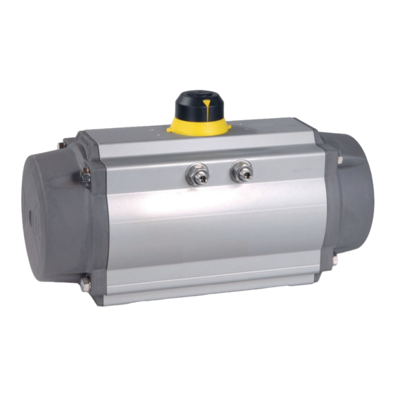
Pneumatic rotary actuator Edition 2010
Single and double-acting piston actuator,
type DAP and SRP
December 2022 edition
PFEIFFER Chemie-Armaturenbau GmbH · Hooghe Weg 41 · 47906 Kempen · Germany
Phone: 02152 2005-0 · Fax: 02152 1580
sales-pfeiffer-de@samsongroup.com · www.pfeiffer-armaturen.com
Advertisement
Table of Contents

Related Manuals for Samson EB 31a


Summary of Contents for Samson EB 31a
- Page 1 MOUNTING AND OPERATING INSTRUCTIONS EB 31a Translation of the original manual Pneumatic rotary actuator Edition 2010 Single and double-acting piston actuator, type DAP and SRP December 2022 edition PFEIFFER Chemie-Armaturenbau GmbH · Hooghe Weg 41 · 47906 Kempen · Germany Phone: 02152 2005-0 ·...
- Page 2 Note regarding this installation and operating manual This Installation and Operating Manual (EB) provides guidance for safe assembly and operation. The notes and instructions in this EB are binding when handling PFEIFFER devices. The fi gures and illustrations in this EB are examples and must therefore be considered as such.
-
Page 3: Table Of Contents
Content Content Safety instructions and safety measures Notes regarding possible severe personnel injury Notes regarding possible personnel injury Notes regarding possible property damage Markings on the device Actuator type plate Design and principle of operation Function Technical data Variants Rotation and travel limit Fail-safe position and direction of action 3.5.1 Single acting rotary actuator (SRP) - Page 4 Content Installation Installation conditions Preparing for assembly Assembling the device 5.3.1 Controls and connections 5.3.2 Assembling the valve and actuator 5.3.3 Assembling accessories Establishing the pneumatic connection Start-up Operation Actuator operation Malfunction Detecting and rectifying errors Carrying out emergency measures Servicing Periodic tests Preparing for maintenance and conversion work...
- Page 5 Content 15 Annex 15-1 15.1 Tightening torques, lubricant and tools 15-1 15.1.1 Tightening torques 15-1 15.1.2 Lubricant 15-2 15.1.3 Tools 15-2 15.2 Spare and wear parts 15-3 15.2.1 Spare parts for rotary actuator DAP/SRP 00015 (rotation angle 0° to 90) 15-4 15.2.2 Spare parts for rotary actuator DAP/SRP 00030 (rotation angle 0°...
- Page 6 Content EB 31a_EN December 2022 edition Subject to technical changes...
-
Page 7: Safety Instructions And Safety Measures
Safety instructions and safety measures Personal protective equipment Safety instructions and safety measures PFEIFFER recommends the following protective equipment when handling the pneumatic rotary actuator BR 31a: Intended use − Protective gloves and safety shoes during assembly and dis- The PFEIFFER-rotary actuator BR 31a Edition 2010 is intended assembly of the actuator. -
Page 8: Notes Regarding Possible Severe Personnel Injury
Safety instructions and safety measures Obligation of operating personnel to exercise diligence 1.2 Notes regarding possible personnel injury Operating personnel must be familiar with this installation and operating manual and the applicable documents and comply WARNING with the indicated hazard information, warning information and other information. -
Page 9: Notes Regarding Possible Property Damage
Safety instructions and safety measures 1.3 Notes regarding possible property damage NOTE Damage to the rotary actuator due to improper fastening of the sling! Do not fasten load-carrying fastening equipment to the travel limit or the optional hand wheel (emergency manual gear). Damage to the rotary actuator due to excessively high or low tightening torques! The rotary actuator components must be tightened with specifi... - Page 10 Safety instructions and safety measures EB 31a_EN December 2022 edition Subject to technical changes...
-
Page 11: Markings On The Device
Markings on the device Markings on the device 2.1 Actuator type plate The actuator type, size, operating pressure, torque, rotation direction, spring effective direction, operating temperature and connection type are specifi ed by the actuator designation. The type plate is glued onto the actuator housing. The type plate contains all data required for device identifi cation. Figure 2-1: Type plate for double-acting rotary actuators (DAP) Figure 2-2:... - Page 12 Markings on the device Table 2-1: Marking on the actuator type plate Information Pos. Remark Distinctive marking: (variable) Order number Item number from the order Serial number (automatic assignment) Accessory connection: (fi xed, depending on the AA1 to AA4 (according to VDE/VDI size 1 to 4) actuator size) Air connection: (fi...
-
Page 13: Design And Principle Of Operation
Design and principle of operation − Rotary actuator for “water” control medium, see data sheet Design and principle of operation DB 31a-14. The PFEIFFER-rotary actuator BR 31a is suitable for use in closed − Rotary actuator with additional travel limit, see data sheet or open environments and is installed on ... -
Page 14: Double-Acting Rotary Actuator (Dap)
Design and principle of operation The standard version of the BR 31a rotary actuator is installed 3.6 Actuation along the valve fl ow direction. When actuated at port “2”, the shaft rotates counterclockwise There are different options for the actuation (90°, 120° or 180° from the start position “CLOSED”... - Page 15 Design and principle of operation Figure 3-5: Exploded drawing of the rotary actuator version Edition 2010 Table 3-1: Parts list for the rotary actuator version Edition 2010 Pos. Designation Pos. Designation Cam (end position adjustment) O-ring Adjusting screw Spring cartridge Lock nut Retaining ring Washer...
-
Page 16: Operating Temperature
Design and principle of operation 3.10 Operating temperature 3.14 Rotary actuator assembly − Standard actuator: Info from -40°C (-40°F) to +80°C (+176°F). − All components are clean and in a perfect condition. − Low temperature actuator SLT with silicon o-rings: −... -
Page 17: Cam Assembly
Design and principle of operation Fit the cam (1) in the desired position in reference to the top Assembling the piston o-ring (16) and bottom position of the shaft, as well as the direction of Fit the piston bearing (5) and piston bearing (15). rotation of the actuator, see Figure 3-6. -
Page 18: End Cap Assembly
Design and principle of operation Check that the pistons in the end position turn the shaft 4° Align the screw head on the end cap surface, see Fig- over the middle line (0°), see Figure 3-11. ure 3-14. Position the seal (111). Fit the washer (103). -
Page 19: Assembly Of The Adjusting Screws, Actuator Version Before 2006
Design and principle of operation Figure 3-19: Assembling the adjusting screws 3.14.5 Assembly of the adjusting screws, actuator version after 2006 (see Figure 3-3 and Figure 3-17) Info Both adjusting screws (2) can only be inserted from the inside of the actuator. -
Page 20: Mounting The Position Indicator
Design and principle of operation Tighten the lock nut (4) to secure the position. Observe the tightening torque for the lock nut, see Table 15.2 in Chapter “15.1.1 Tightening torques”. 3.14.7 Mounting the position indicator (see Figure 3-3 and Figure 3-18) Figure 3-20: Assembling the position indicator Place the position indicator (19) on the shaft and pay atten-... -
Page 21: Shipment And On-Site Transport
Shipment and on-site transport Shipment and on-site transport NOTE The work described in this chapter may only be performed by Damage to the actuator due to improper fastening of the sling! specialist personnel qualifi ed to perform the corresponding task. The screwed-in eyebolts on PFEIFFER rotary actuators are used only for actuator assembling and disassembling as well as for lifting the actuator without the valve. - Page 22 Shipment and on-site transport Figure 4-1: Lifting points on the actuator up to DAP/SRP 1200 Figure 4-3: Eyebolts Figure 4-2: Lifting points on the actuator from DAP/SRP 2000 EB 31a_EN December 2022 edition Subject to technical changes...
- Page 23 Shipment and on-site transport Table 4-1: Eyebolt sizes Actuator size Eyebolt according to DIN 580 DAP/SRP 02000 DAP/SRP 03000 DAP/SRP 04000 DAP/SRP 05000 DAP/SRP 10000 Figure 4-4: Lift-kit Lift the actuator (without the valve) Use a hook with a safety clamp as the suspension element so that the sling cannot slip off the hook during lifting and trans- port, see Figure 4-1 and Figure 4-2.
- Page 24 Shipment and on-site transport Table 4-3: “Lift kit” components Table 4-4: Maximum load to be lifted SRP/DAP Weight in Screw on max. ZG DAP/SRP Eyebolts actuator the end cap in kg actuator 00300 12.6 4x M10x35 00015 00450 18.1 4x M10x35 00030 00600 4x M12x50...
-
Page 25: Storing The Actuator
Shipment and on-site transport Table 4-5: Maximum permissible additional weight Storage conditions If the valve and actuator are already assembled, observe the max. max. load storage conditions for the respective valve, see the corre- DAP/SRP Threaded Weight permissible for both sponding documentation for the valve. - Page 26 Shipment and on-site transport EB 31a_EN December 2022 edition Subject to technical changes...
-
Page 27: Installation
Installation Installation WARNING The work described in this chapter may only be performed by Danger of injury due to preloaded springs! specialist personnel qualifi ed to perform the corresponding task. The rotary actuators are tensioned due to the compressed springs. Furthermore, improper disassembly of the spring car- tridge can lead to serious injuries. -
Page 28: Controls And Connections
Installation 5.3.1 Controls and connections The assembly of the valve and actuator takes place according to the signal range and direction of action of the actuator. This in- formation is available on the type plate of the actuator, see Chapter “2 Markings on the device”. Figure 5-1: Connections 5.3.2 Assembling the valve and actuator... -
Page 29: Assembling Accessories
Installation Place the rotary actuator (A) on the bracket (C) and fasten PFEIFFER rotary actuators can be controlled by directly assem- with the corresponding screws. Observe the tightening tor- bled devices or remote control systems. ques, see “Table 15-5 Tightening torques on the ISO connec- Therefore the rotary actuators have direct interfaces for the as- tion”... - Page 30 Installation Supply air to port “4” moves the pistons in the middle, see Figure 5-5. Air supply to port “2” requires a clockwise direc- tion of rotation. Single-acting actuator (standard direction of rotation) Figure 5-6: Air supply “2” Figure 5-7: Loss of pressure Supply air to port “2”...
-
Page 31: Start-Up
Start-up Start-up NOTE The work described in this chapter may only be performed by Damage to the actuator due to excessively high or low tighten- specialist personnel qualifi ed to perform the corresponding task. ing torques! The rotary actuator components and additional equipment must DANGER be tightened with specifi... - Page 32 Start-up EB 31a_EN December 2022 edition Subject to technical changes...
-
Page 33: Operation
Operation The rotary actuator can be operated after connection to the sup- Operation ply line and adjustment of the rotation angle. The work described in this chapter may only be performed by Single-acting rotary actuators with spring return are operated by specialist personnel qualifi... - Page 34 Operation EB 31a_EN December 2022 edition Subject to technical changes...
-
Page 35: Malfunction
Malfunction Malfunction When rectifying the faults, chapter “1 Safety instructions and safety measures” must be observed. 8.1 Detecting and rectifying errors Type of fault Possible cause Measures The actuator shaft does not The actuator is mechanically Check the installation. move even if requested. blocked. -
Page 36: Carrying Out Emergency Measures
Malfunction Type of fault Possible cause Measures Loss of power Signal pressure too low Check the control system, Ensure a correct supply pressure. Supply line blocked, crushed or Check the pipes and fi ttings. leaky Remove foreign matter/damaged components. Leakage in the rotary actuator Disassemble the rotary actuator, see chapter “1 Safety instructions and safety seals measures”. -
Page 37: Servicing
Servicing Servicing NOTE The work described in this chapter may only be performed by Damage to the actuator due to excessively high or low tighten- specialist personnel qualifi ed to perform the corresponding task. ing torques! The following documents are required in addition for the mainte- The rotary actuator components and additional equipment must nance of the ball valve: be tightened with specifi... -
Page 38: Assembling The Valve After Maintenance And Conversion Work
Servicing Unscrew the screws on the end cap and put them down to the side. After the preparation, the maintenance and/or conversion work can be carried out. 9.3 Assembling the valve after maintenance and conversion work Assemble the actuator, see Chapter “5 Assembly”. Adjust the upper and lower signal range, see Chapter “6 Commissioning”. - Page 39 Servicing WARNING Danger of injury due to defective springs! The end caps are tensioned when the springs are compressed. If after unscrewing the screws (13) with the number of rotations specifi ed in Table 9-1 force is still applied on the end caps (23 and 23), the spring cartridge is possibly damaged or the pistons are not completely closed.
- Page 40 Servicing Check that the pistons in the end position turn the shaft 4° over the middle line (0°), see Figure 9-8. Figure 9-8: Piston end position In the case of single-acting actuators, insert the spring cartridge in the end cap. Figure 9-9: Assembling the spring cartridges Figure 9-11: Assembling the end cap screws...
-
Page 41: Ordering Spare Parts And Consumables
Servicing Tighten the screw (24). Attach a new type plate to the actuator with the changed direction of action. 9.6 Ordering spare parts and consumables Information about spare parts, lubricants and tools can be received from the After Sales Service at PFEIFFER. Spare parts Information on spare parts can be found in Chapter “15.2 Wear parts and spare parts“. - Page 42 Servicing EB 31a_EN December 2022 edition Subject to technical changes...
-
Page 43: Decommissioning
Decommissioning 10 Decommissioning Info The work described in this chapter may only be performed by − Before any disassembly work is performed, it is important to specialist personnel qualifi ed to perform the corresponding task. make sure that the actuator is not pressurised and the springs are released in the end position. - Page 44 Decommissioning EB 31a_EN 10-2 December 2022 edition Subject to technical changes...
-
Page 45: Removal
Removal 11 Removal 11.1 Releasing the spring tension in the actuator The work described in this chapter may only be performed by specialist personnel qualifi ed to perform the corresponding task. The end caps (22 and 23) are tensioned due to the compressed springs. -
Page 46: Disassembling The Actuator
Removal 11.2 Disassembling the actuator Figure 11-2: Disassembling the end cap Release the spring compression. Unscrew each end cap screw (13) one rotation each according to the order shown in Figure 11-1 and the number of rotations specifi ed in Table 11-1. -
Page 47: Repairs
Repairs 12 Repairs 12.1.2 Remove the adjusting screws, actuator version before 2006 If the operation of the rotary actuator is no longer compliant or if it does not work at all, it is defective and must be repaired or (see Figure 12-3 and Figure 12-2) replaced. - Page 48 Repairs Figure 12-3: Exploded drawing of the rotary actuator version after 2010 Table 12-1: Parts list Pos. Designation Pos. Designation Cam (end position adjustment) O-ring Adjusting screw Spring cartridge Lock nut Retaining ring Washer Position indicator Bearing (piston back) Shaft seal (bottom) Shaft bearing bushing (top) Shaft seal (top) Shaft bearing bushing (bottom)
-
Page 49: End Cap Disassembly
Repairs 12.1.4 End cap disassembly (see Figure 12-3, Figure 12-4 and Figure 12-5) Disassemble one end cap after the other. Disassemble the end cap screws (13) according to the order of the disassembly sequence, see Figure 12-4. For single-acting actuators, remove the spring cartridge (17). WARNING Danger of damage to components due to incorrect disassem- bly! -
Page 50: Piston Disassembly
Repairs 12.1.5 Piston disassembly (see Figure 12-3 and Figure 12-6) If the shaft cannot be removed by hand, gently tap the top of the shaft with a plastic mallet to drive it out. Remove the top and bottom shaft bearings (6 and 7). Remove the top and bottom seals (20 and 21). -
Page 51: Disposal
Disposal 13 Disposal For disposal, observe the local, national and international regulations. Do not dispose of old components, lubricant and hazardous materials with domestic waste. EB 31a_EN 13-1 December 2022 edition Subject to technical changes... - Page 52 Disposal EB 31a_EN 13-2 December 2022 edition Subject to technical changes...
-
Page 53: Certifi Cates
Certifi cates 14 Certifi cates The declarations of conformity are available on the following page: − Declaration of conformity in compliance with the EU Machinery Directive 2006/42/EU, see page 14-2. − Declaration of conformity in compliance with the ATEX Directive 2014/34/EU, see page 14-2. −... - Page 54 Certifi cates EB 31a_EN 14-2 December 2022 edition Subject to technical changes...
- Page 55 Certifi cates EB 31a_EN 14-3 December 2022 edition Subject to technical changes...
- Page 56 Certifi cates EB 31a_EN 14-4 December 2022 edition Subject to technical changes...
-
Page 57: Annex
Annex 15 Annex Rotary actuator Tightening torque Thread DAP / SRP in Nm 15.1 Tightening torques, lubricant and tools 00150 34 => 36 00220 60 => 64 15.1.1 Tightening torques 00300 00450 Info 96 => 102 00600 − All tightening torques are indicated in Nm. −... -
Page 58: Lubricant
Annex Table 15-4: Tightening torque on the port (NAMUR) Table 15-6: Tightening torques on the accessory connection Rotary actuator Tightening torque Tightening Thread Rotary actuator Accessory con- DAP / SRP in Nm Thread torque DAP / SRP nection in Nm 00015 00015 00030... -
Page 59: Spare And Wear Parts
Annex Figure 15-8: Tool dimensions 15.2 Spare and wear parts Table 15-8: Tool dimensions PFEIFFER recommends wear part sets for “Commissioning” and Rotary actuator SW 1 SW 2 SW 3 SW 4 for “2-year operation”. DAP/SRP The recommended spare parts for the standard, high temperature 00015 and low temperature actuators of the BR 31a are listed in the fol- 00030... -
Page 60: Spare Parts For Rotary Actuator Dap/Srp 00015 (Rotation Angle 0° To 90)
Annex 15.2.1 Spare parts for rotary actuator DAP/SRP 00015 (rotation angle 0° to 90) Figure 15-9: Sectional drawing of the rotary actuator DAP/SRP 00015 Table 15-9: Recommended spare parts for rotary actuator DAP/SRP 00015. Pos. Quantity Description Material Stainless steel Adjusting screw Stainless steel Washer... -
Page 61: Spare Parts For Rotary Actuator Dap/Srp 00030 (Rotation Angle 0° To 90)
Annex 15.2.2 Spare parts for rotary actuator DAP/SRP 00030 (rotation angle 0° to 90) Figure 15-10: Sectional drawing of the rotary actuator DAP/SRP 00030 Table 15-10: Recommended spare parts for rotary actuator DAP/SRP 00030 Pos. Quantity Description Material Stainless steel Adjusting screw Stainless steel Washer... -
Page 62: Spare Parts For Rotary Actuator Dap/Srp 00060 To 02000 (Rotation Angle 0° To 90)
Annex 15.2.3 Spare parts for rotary actuator DAP/SRP 00060 to 02000 (rotation angle 0° to 90) Figure 15-11: Sectional drawing of the rotary actuator DAP/SRP 00060 to 02000 Table 15-11: Recommended spare parts for rotary actuator DAP/SRP 00060 to 02000 Pos. -
Page 63: Spare Parts For Rotary Actuator Dap/Srp 03000 To 04000 (Rotation Angle 0° To 90)
Annex 15.2.4 Spare parts for rotary actuator DAP/SRP 03000 to 04000 (rotation angle 0° to 90) Figure 15-12: Sectional drawing of the rotary actuator DAP/SRP 03000 to 04000 Table 15-12: Recommended spare parts for rotary actuator DAP/SRP 03000 to 04000 Pos. -
Page 64: Spare Parts For Rotary Actuator Dap/Srp 05000 (Rotation Angle 0° To 90)
Annex 15.2.5 Spare parts for rotary actuator DAP/SRP 05000 (rotation angle 0° to 90) Figure 15-13: Sectional drawing of the rotary actuator DAP/SRP 05000 Table 15-13: Recommended spare parts for rotary actuator DAP/SRP 05000 Pos. Quantity Description Material C-steel, zinc coated Adjusting screw Stainless steel Washer... -
Page 65: Spare Parts For Rotary Actuator Dap/Srp 10000 (Rotation Angle 0° To 90)
Annex 15.2.6 Spare parts for rotary actuator DAP/SRP 10000 (rotation angle 0° to 90) Figure 15-14: Sectional drawing of the rotary actuator DAP/SRP 10000 Table 15-14: Recommended spare parts for rotary actuator DAP/SRP 10000 Pos. Quantity Description Material C-steel, zinc coated Adjusting screw Stainless steel Washer... -
Page 66: Wear Part Sets For Rotary Actuator Dap/Srp 00015 To 10000
Annex 15.2.7 Wear part sets for rotary actuator DAP/SRP 00015 to 10000 Table 15-15: Wear part sets Rotary actuator Wear part sets DAP/ SRP Standard (STD) High temperature (HT) Low temperature (SLT) 00015 43718v 45444v 48021v 00030 43719v 45445v 48022v 00060 43720v 45435v... - Page 67 EB 31a_EN December 2022 edition Subject to technical changes...
- Page 68 PFEIFFER Chemie-Armaturenbau GmbH Hooghe Weg 41 · 47906 Kempen · Germany Phone: +49 2152 2005-0 · Fax: +49 2152 1580 E-Mail: sales-pfeiffer-de@samsongroup.com · Internet: www.pfeiffer-armaturen.com EB 31a_EN December 2022 edition Subject to technical changes...
Need help?
Do you have a question about the EB 31a and is the answer not in the manual?
Questions and answers