
Related Manuals for Novus RHT-WM-485-LCD


Summary of Contents for Novus RHT-WM-485-LCD
- Page 1 RHT-WM-485-LCD, RHT-DM-485-LCD and RHT-P10-485-LCD TEMPERATURE AND HUMIDITY TRANSMITTER USER GUIDE V2.0x A...
-
Page 2: Table Of Contents
SAFETY ALERTS .......................................3 INTRODUCTION ........................................4 IDENTIFICATION ......................................4 MECHANICAL INSTALLATION ..................................5 RHT-DM-485-LCD .......................................5 RHT-WM-485-LCD ......................................5 RHT-P10-485-LCD ......................................6 ELECTRICAL INSTALLATION ...................................7 INSTALLATION RECOMMENDATIONS ..............................7 CONFIGURATION / OPERATION ..................................8 SCREENS OF THE TRANSMITTER ................................8 SERIAL COMMUNICATION ....................................9 MODBUS COMMANDS ....................................9 DESCRIPTION OF SOME REGISTERS ..............................9 HOLDING REGISTERS TABLE ................................10... -
Page 3: Safety Alerts
All safety recommendations appearing in this manual must be followed to ensure personal safety and prevent damage to the instrument or system. If the instrument is used in a manner other than that specified in this manual, the device’s safety protections may not be effective. NOVUS AUTOMATION 3/14... -
Page 4: Introduction
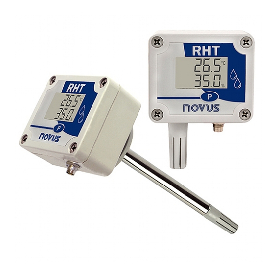
The identification label is fixed on the transmitter body. Check if the features described on this label are in accordance with your order. The RHT-WM-485-LCD and RHT-P10-485-LCD models intended for wall mounting, while the RHT-DM-485-LCD model comes with a probe tip rod for installation in ducts or through walls. -
Page 5: Mechanical Installation
Dimensions of the RHT-DM-485-LCD model RHT-WM-485-LCD The RHT-WM-485-LCD (Wall Mount) model is designed for wall mounting. Removing the transmitter cover gives the user access to two bores for fixing the base, as shown in the figure below. The transmitter must be fixed with the sensor capsule directed downwards to assure the specific accuracy and protection level. -
Page 6: Rht-P10-485-Lcd
Figure 6 – Dimensions of the RHT-WM-485-LCD model RHT-P10-485-LCD The RHT-P10-485-LCD electronic housing is designed for wall mounting, while its remote sensor probe is intended for inserting and screwing in a flange. Figure 7 – Remote sensor dimensions Figure 8 –... -
Page 7: Electrical Installation
In control and monitoring applications it is essential to consider what can happen if any part of the system should fail. • We recommend the use of RC FILTERS (47Ω and 100nF, series) in parallel with contactor and solenoid coils etc. • NOVUS AUTOMATION 7/14... -
Page 8: Configuration / Operation
(Parity) = Par Stop Bit = 1 DigiConfig for Windows is a software used for configuration of the RHT-WM-485-LCD, RHT-DM-485-LCD and RHT-P10-485-LCD transmitters. For its installation, run the “DigiConfigSetup.exe” and follow the instructions as shown. DigiConfig comes with an unabridged help tutorial, containing all the necessary information for you to use it. If you want to use help tutorial, start the application, and select the Help menu or press F1. -
Page 9: Serial Communication
Defines the indication mode on the display of the sensor values readout. The transmitter comes factory-configured with indication of temperature and relative humidity. CODE DESCRIPTION Indicates temperature and relative humidity. Indicates temperature and dew point. Indicates relative humidity and dew point. Indicates temperature only. Table 4 – Indication mode NOVUS AUTOMATION 9/14... -
Page 10: Holding Registers Table
Firmware release Indication mode Temperature value (°C or °F)* -400 1000 Relative humidity value (%)* 1000 Dew point value (°C or °F)* -400 1000 Configuration of measurement unit Disables configuration via button User offset for temperature* -100 NOVUS AUTOMATION 10/14... - Page 11 MAXIMUM Reserved User offset for humidity* -100 Reserved Error value -9999 9999 Title Title Title Title Title Model Table 7 – Registers * For the ranges indicated above consider with one decimal place. Example: -100 means -10.0. NOVUS AUTOMATION 11/14...
-
Page 12: Special Care
The sensor used in this transmitter may be damaged or become out of calibration if it is exposed to chemical agents contaminated atmosphere. Hydrochloric Acid, Nitric Acid, Sulfuric Acid, and Ammonia in high concentrations may damage the sensor. Acetone, Ethanol and Propylene Glycol may cause a reversible measurement error. NOVUS AUTOMATION 12/14... -
Page 13: Specifications
SPECIFICATIONS FEATURES RHT-WM-485-LCD, RHT-DM-485-LCD, and RHT-P10-485-LCD WM Model: From -40 °C to 70 °C. • Transmitter operating DM Model: From -40 °C to 100 °C. • temperature Sensor and Rod (RHT-DM): See Figure 11. Temperature: -40 °C to 100°C. Sensor measuring range Relative Humidity (RH): 0 to 100 % RH (No Condensing). -
Page 14: Warranty
WARRANTY Warranty conditions are available on our website www.novusautomation.com/warranty. NOVUS AUTOMATION 14/14...
Need help?
Do you have a question about the RHT-WM-485-LCD and is the answer not in the manual?
Questions and answers