
Related Manuals for Novus RHT Climate-WM Series


Summary of Contents for Novus RHT Climate-WM Series
- Page 1 RHT ClimateTransmitter WM and DM models INSTRUCTION MANUAL V1.2x A Applies to devices with firmware version starting with V1.2x. NOVUS AUTOMATION 1/48...
-
Page 2: Table Of Contents
OUTPUT PARAMETERS ................................... 39 11.3.4 HMI PARAMETERS.................................... 41 11.3.5 FINALIZATION PARAMETERS ................................. 43 11.4 DIAGNOSTICS......................................44 11.4.1 INPUT DIAGNOSTICS ..................................44 11.4.2 OUTPUT DIAGNOSTICS ................................... 45 TECHNICAL SPECIFICATIONS ..................................46 WARRANTY ......................................... 47 APPENDIX I – NOTIONS ABOUT PSYCHROMETRY............................48 NOVUS AUTOMATION 2/48... -
Page 3: Safety Alerts
All safety recommendations appearing in this manual must be followed to ensure personal safety and prevent damage to the instrument or system. If the instrument is used in a manner other than that specified in this manual, the device’s safety protections may not be effective. NOVUS AUTOMATION 3/48... -
Page 4: Introduction
Psychrometry is the study of thermodynamic properties of dry air and water vapor mixtures. Obtaining the psychrometric properties is crucial in the psychrometric processes of air conditioning, refrigeration, cooling and freezing, air humidification and dehumidification, drying and dehydration of humid devices, as well as in environmental and meteorological control. NOVUS AUTOMATION 4/48... -
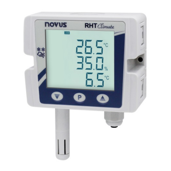
Page 5: Identification
IDENTIFICATION MODELS WITHOUT DISPLAY Fig. 01 – Device without display MODELS WITH DISPLAY Fig. 02 – Device with display Fig. 03 – Display indications NOVUS AUTOMATION 5/48... -
Page 6: Device Models
RHT Climate-DM-250S 250 mm RHT Climate-DM-250S-485 250 mm RHT Climate-DM-250S-485-LCD 250 mm RHT Climate-DM-400S 400 mm RHT Climate-DM-400S-485 400 mm RHT Climate-DM-400S-485-LCD 400 mm Table 01 – Available RHT Climate models NOVUS AUTOMATION 6/48... -
Page 7: Display Indications
After the screens of maximum and minimum values, are available screens for viewing other psychrometric variables. The device will advance one screen each short touch of the key , respecting the following sequence: Fig. 08 - Wet bulb temperature Fig. 09 - Absolute humidity Fig. 10 - Frost point temperature NOVUS AUTOMATION 7/48... -
Page 8: Signals
: Indicates that the value to be displayed on one of the lines is above the display limit. • vvvv : Indicates that the value to be shown on one of the lines is below the display limit • NOVUS AUTOMATION 8/48... -
Page 9: Installation
The RHT Climate Transmitter DM model it is mounted via a flange. First the flange is mounted on the duct wall, then the transmitter rod is inserted into the central bore hole on the flange and secured. 5.1.1 DIMENSIONS 5.1.1.1 RHT Climate TRANSMITTER (WM MODEL) Fig. 15 – Dimensions of WM model NOVUS AUTOMATION 9/48... -
Page 10: Rht Climate Transmitter (Dm Model)
Fig. 19 - Removing the front cover of the transmitter To install, fit the cover onto the base by pressing it with care to fully secure the transmitter, as shown in the figure below: Fig. 20 - Device cover fitting NOVUS AUTOMATION 10/48... -
Page 11: Electrical Installation
• Place the sensor in an oven at 120 °C (+/-10 °C) for 6 hours; • Carefully replace the sensor in the capsule. It is also possible to clean or dry the sensor using filtered and oil-free air, taking care that the air jets do not mechanically damage the sensor. NOVUS AUTOMATION 11/48... -
Page 12: Sensor Replacement
Do not hold the sensor by the sensor element. Do not use metal tweezers. Do not touch the sensor without wearing gloves. Step 5: Place the protection tip again and turn it clockwise to secure it to the device. • NOVUS AUTOMATION 12/48... -
Page 13: Parameter Cycles
You also can enable the protection of the configuration parameters and change the password. 11 - Information Cycle: In this cycle are displayed the serial number (sn) and the firmware version (firm) of the device. Table 02 – Parameter cycles NOVUS AUTOMATION 13/48... -
Page 14: Configuration
Type of signal from analog outputs 0vt1 / 0vt2 Default: 4-20 0vt1 modE Analog output 1 operating in mode 4-20 mA 4-20 Analog output 1 operating in mode 0-10 V 0vt2 0-10 modE Table 05 – Type of signal from analog outputs NOVUS AUTOMATION 14/48... -
Page 15: Alarm Outputs Alm1 / Alm2
For each alarm output and for the buzzer, the following can be configured: The associated psychrometric property; • Alarm type Lo, , -L • i, L-- The setpoints; • Hysteresis; • Output condition in case of sensor error; • And the timing. • NOVUS AUTOMATION 15/48... - Page 16 The initial block is useful, for example, when one of the alarms is configured as minimum value alarm, potentially setting off the alarm right when the process is started up, which is often undesirable behavior. Initial blocking is not valid for the Sensor Open function. NOVUS AUTOMATION 16/48...
- Page 17 These values extrapolate the maximum value that can be shown by the display. Using the HMI, you can set up to the limit of 19999. When configured via NXperience, these parameters nnnn can be adjusted up to the values shown on the table above, but when accessing these parameters via the HMI, they will display the value NOVUS AUTOMATION 17/48...
- Page 18 Time of alarms on 6500 Alm2 Table 15 – Time of alarms on 7.2.7 Alarms off time ALM1 / ALM2 Min. Max. Unit Default ALm1 T0ff Time of alarms off 6500 Alm2 T0ff Table 16 – Time of alarms off NOVUS AUTOMATION 18/48...
-
Page 19: Buzzer Configuration Cycle
Activates the alarm in case of sensor error iErr Bv22 Activates alarm below setpoint SPLo modE Activates alarm above setpoint SPki Activates alarm between SPLo and SPki L--k Activates alarm below SPLo and above SPki -Lk- Table 21 – Buzzer activation mode NOVUS AUTOMATION 19/48... - Page 20 Absolute humidity g/m³ gr/ft³ kyst Frost point temperature °C °F Specific enthalpy kJ/kg BTU/lb Partial vapor pressure mbar Mixture ratio g/kg gr/lb Table 24 – Hysteresis for turning off buzzer 7.3.6 Buzzer on time Min. Max. Unit Default NOVUS AUTOMATION 20/48...
-
Page 21: Hmi Configuration Cycle
Contrast 2 (-20° in relation to the horizontal line) Contrast 3 (0° in relation to the horizontal line) Cont Contrast 4 (+20° in relation to the horizontal line) Contrast 5 (+40° in relation to the horizontal line) Table 30 – Contrast NOVUS AUTOMATION 21/48... - Page 22 It allows you to configure the information to be displayed on the third line of the display. Third line of the display Default: Td Dew point Wet bulb temperature Absolute humidity Frost point lin3 Specific enthalpy Partial vapor pressure Mixture ratio None Table 33 – Third line of the display NOVUS AUTOMATION 22/48...
-
Page 23: Diagnostic Cycle
Table 37 – Forces alarm output ALM1 / alm2 7.5.5 Buzzer forcing It allows you to force buzzer activation. Forces buzzer output Default: Off diAG Forces buzzer off output Fb22 Forces buzzer on output Table 38 – Buzzer forcing NOVUS AUTOMATION 23/48... -
Page 24: Communication Cycle
This parameter configures the address for RHT Climate Transmitter communication on a Modbus-RTU network. This parameter should be adjusted so that no two devices use the same address within a Modbus-RTU network. Min. Max. Unit Default [nfG Internet address Addr Table 41 – Address NOVUS AUTOMATION 24/48... -
Page 25: General Configuration Cycle
Table 45 – Digital relative humidity reading filter 7.7.5 Temperature reading offset This parameter allows for correcting offset displacement in the temperature reading. Min. Max. Unit Default Min. Max. Unit Default [nfG Temperature reading offset °C °F Table 46 – Temperature reading offset NOVUS AUTOMATION 25/48... - Page 26 As of this moment, the protection will be disabled. If the protection is enabled and you attempt to alter any parameter, the transmitter will show the Prot message on the display instead of the defined value. NOVUS AUTOMATION 26/48...
-
Page 27: Information Cycle
INFORMATION CYCLE In the information cycle, the RHT Climate Transmitter displays the serial number (Sn) and firmware version (firm) of the device. Fig. 26 - Serial number and firmware version information NOVUS AUTOMATION 27/48... -
Page 28: Parameters Map
Wet bulb temperature Scrn kyst kyst kyst FLrk FAl1 Lin3 Absolute humidity FAl2 Frost point temp. 0frk T0ff T0ff T0ff Fb22 Enthalpy PAss Partial vapor pressure prot Mixture ratio Bv22 Bv22 Table 50 – Device parameters map NOVUS AUTOMATION 28/48... -
Page 29: Usb Interface
For MONITORING for long periods and with inputs and outputs connected, use of the RS485 interface is recommended, available or optional in most of our devices. NOVUS AUTOMATION 29/48... -
Page 30: Serial Communication
Maximum dew point value -9000 1000 -13000 2120 Table 51 – Primary cycle indication registers For firmware version less than or equal to 1.10, the maximum enthalpy value is 32767 and the maximum mix ratio value is 65535. NOVUS AUTOMATION 30/48... - Page 31 The limits depend on the psychrometric property configured Low Setpoint input for alarm at address 133. Alarm blocking Alarm hysteresis Alarm ON time 6500 6500 Alarm OFF time 6500 6500 Determines the alarm status in case of sensor error NOVUS AUTOMATION 31/48...
- Page 32 Determines buzzer activation The limits depend on the psychrometric property configured Alarm Setpoint High at address 167. The limits depend on the psychrometric property configured Alarm Setpoint Low at address 167. Table 57 – Alarm ALM3 Output Registers NOVUS AUTOMATION 32/48...
- Page 33 CHARACTER 2 CHARACTER 1 ASCII CHARACTER 4 CHARACTER 3 ASCII CHARACTER 6 CHARACTER 5 ASCII Device name string CHARACTER 8 CHARACTER 7 ASCII CHARACTER 10 CHARACTER 9 ASCII CHARACTER 12 CHARACTER 11 ASCII CHARACTER 14 CHARACTER 13 NOVUS AUTOMATION 33/48...
- Page 34 Target humidity value 5 1000 1000 Table 63 – Sensor Linearization Registers DEVICE INFORMATION REGISTERS Address Description High serial number Low serial number Firmware version Release version Informs the device model Table 64 – Device Information Registers NOVUS AUTOMATION 34/48...
- Page 35 If the limits were extrapolated, this condition will be signaled in the diagnostic register 343. For 32-bit data, the two registers that compose them must be read and/or written in order for the values to be updated. NOVUS AUTOMATION 35/48...
-
Page 36: Nxperience Software
The Create Configuration button creates a configuration from scratch. The device does not need to be plugged into the computer's USB port. This configuration can be saved in a file for future use, or saved to a connected device. The Open Configuration button is used for reading from an already created configuration file. NOVUS AUTOMATION 36/48... - Page 37 Finalization: In this tab, you can send the configuration to the device, save the configuration in a file, update the device firmware, and configure a password to protect the device. Back: By clicking this button you can return to the home screen of NXperience. NOVUS AUTOMATION 37/48...
-
Page 38: General Parameters
To obtain higher precision from the sensor, the device offers the Custom Calibration feature, which lets you insert up to five temperature points and five points for relative humidity. To make this adjustment, click on to access the custom calibration window. For further details about this feature, refer to the NXperience manual at www.novusautomation.com. NOVUS AUTOMATION 38/48... -
Page 39: Output Parameters
In case of sensor failure, the variable to be transmitted by the analog output will go into Error Mode. For this error condition, you can select High or Low status. Error mode Mode High 0 - 10 V 10 V 4 - 20 mA 3.6 mA 21.0 mA Table 66 – Error mode NOVUS AUTOMATION 39/48... - Page 40 *The buzzer can only be linked to an alarm output in LCD models. To select the buzzer configurations, click once on the button and enable it by sliding the enable key right. Fig. 36 – Alarm 3 The buzzer configurations are similar to those of alarms 1 and 2. NOVUS AUTOMATION 40/48...
-
Page 41: Hmi Parameters
The buzzer and the alarm output will only be reactivated if the RHT Climate Transmitter goes into a non-alarm condition and returns to an alarm condition. NOVUS AUTOMATION 41/48... - Page 42 Specific Enthalpy: The third line will display the current value of the specific enthalpy. • Partial Vapor Pressure: The third line will display the current value of the partial vapor pressure. • Mixture Ratio: The third line will display the current value of the mixture ratio. • NOVUS AUTOMATION 42/48...
-
Page 43: Finalization Parameters
, the software will display the screen below and you can send the configuration to the device, save the configurations in a file, update the device firmware, and configure a password to protect the device. Fig. 41 – Finalization parameters NOVUS AUTOMATION 43/48... -
Page 44: Diagnostics
The other psychrometric properties are calculated by the RHT Climate Transmitter based on these values. Note that the button that was used for forcing temperature changed to Fig. 43 – Diagnostics Input Parameters NOVUS AUTOMATION 44/48... -
Page 45: Output Diagnostics
The images below show the interface for forcing alarm output 1 in the three possible conditions: Without forcing, forcing in on state, and forcing in off state. Fig. 46 – Alarm 1 output without forcing Fig. 47 – Alarm 1 output with forcing in on state Fig. 48 – Alarm 1 output with forcing in off state NOVUS AUTOMATION 45/48... -
Page 46: Technical Specifications
Menus in Portuguese, Spanish, French and English. CE Mark Certifications This is a Class A product. In a domestic environment, this product may cause radio interference in which case the user may be required to take adequate measures. Table 67 – Technical specifications NOVUS AUTOMATION 46/48... -
Page 47: Warranty
WARRANTY Warranty conditions are available on our website www.novusautomation.com/warranty. NOVUS AUTOMATION 47/48... -
Page 48: Appendix I - Notions About Psychrometry
The mixture ratio varies with temperature, except if the temperature is lower than the dew point, or when the air is completely saturated with water vapor. In these conditions, the drop in temperature will cause forced water condensation. NOVUS AUTOMATION 48/48...
Need help?
Do you have a question about the RHT Climate-WM Series and is the answer not in the manual?
Questions and answers