Advertisement
Quick Links
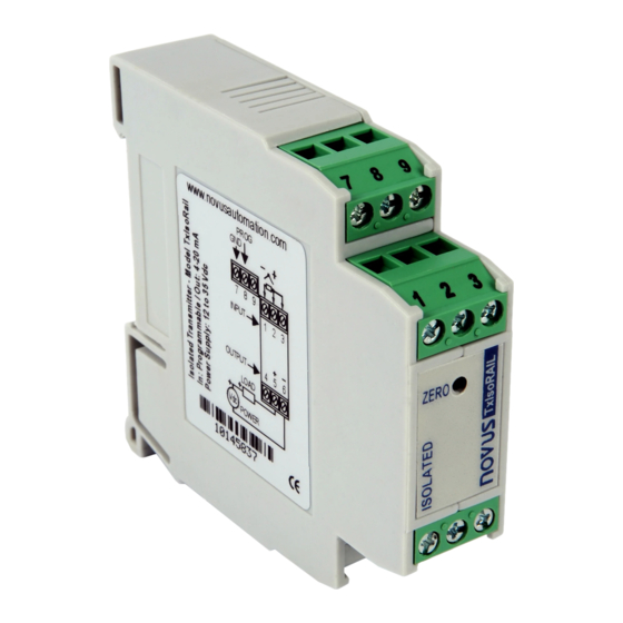
TxIsoRail 4-20 mA
MICROPROCESSOR BASED TEMPERATURE TRANSMITTER –
OPERATION MANUAL V1.0x F
SPECIFICATIONS
Sensor input: User defined. The supported sensors are listed in Table 1,
along with their maximum ranges.
Thermocouples: Types J, K, R, S, T, N, E and B to IEC 60584 (ITS-90).
Impedance >> 1 M
Pt100:
Excitation: 180 µA, 2 or 3-wire connection (for 2-wire
sensors, tie, terminals 2 and 3 together).
α= 0.00385, according to IEC 60751 (ITS-90).
Voltage:
0 to 50 mVdc, 0 to 10 Vdc. Impedance >> 1 M
Note: 0-10 Vdc input type requires an internal jumper
*
switching.
0 to 20 mA, 4 to 20 mA. Impedance 15.0
Sensor Type
Range
Thermocouple K
-150 to 1370 °C / -238 to 2498 ºF
Thermocouple J
-100 to 760 °C / -148 to 1400 ºF
Thermocouple R
-50 to 1760 °C / -58 to 3200 ºF
Thermocouple S
-50 to 1760 °C / -58 to 3200 ºF
Thermocouple T
-160 to 400 °C / -256 to 752 ºF
Thermocouple N
-270 to 1300 °C / -454 to 2372 ºF
Thermocouple E
-90 to 720 °C / -130 to 1328 ºF
Thermocouple B
500 to 1820 °C / 932 to 3308 °F
Pt100
-200 to 600 °C / -328 to 1112 ºF
0 to 50 mV
Voltage
*
0 to 10 V
0 to 20 mA
Current
4 to 20 mA
Table 1 – Transmitter input sensors
Output: 2-wire 4-20 mA, linear with respect to the measured signal.
Resolution: 0.001 mA (14 bits)
Total Accuracy:
Better than 0.3 % of the maximum span for
thermocouples and 0.2 % for Pt100 and voltage;
Response Time: < 500 ms
Isolation: Between the sensor and the 4-20 mA loop (1000 V / 1 min).
Power Supply: 12 to 35 Vdc, across the transmitter;
Maximum Load (RL): RL (max.)= (Vdc – 12) / 0.02 [Ω]
Were: Vdc= Power supply voltage
Operating Temperature: -40 to 85 °C
Humidity: 0 to 90 % UR
Electromagnetic Compatibility: EN 50081-2, EN 50082-2
Internal protection against polarity inversion.
Cold junction compensation for thermocouples.
NOVUS AUTOMATION
Ω
Ω.
(+ 1.9 Vdc).
Ω
Minimum measurement span
100 °C
100 °C
400 °C
400 °C
100 °C
100 °C
100 °C
400 °C
40 °C
5 mV
1 V
2 mA
2 mA
CONFIGURATION
If the transmitter is already configured as required by the application (sensor
type, range, etc), it may be installed and used right away. However, if a
distinct configuration is required, this can be done through the TxConfig
software and the TxConfig Interface.
The TxConfig interface and software can be purchased from the manufacturer
or at its authorized distributors and representatives. Updates for the software
are available at our website. To install the TxConfig software, run the
Tx_setup.exe file and follow the instructions.
Serial port configuration errors may occur when other devices are
sharing the same port (ex.: Palm Hot Synch). Close all serial port
applications prior to using the TxConfig software.
The TxConfig interface connects the transmitter to the PC, as shown in Fig.
1 and 2. There are two types of interface: TxConfig-RS232 and TxConfig-
USB.
Fig. 1 – TxConfig Interface connections model RS232
Fig. 2 – TxConfig Interface USB connections
Once the connection is accomplished, the software shows the configuration
options of the transmitter model attached. Access the Help for usage
instructions.
1/3
Advertisement

Subscribe to Our Youtube Channel
Related Manuals for Novus TxIsoRail


Summary of Contents for Novus TxIsoRail
- Page 1 TxIsoRail 4-20 mA MICROPROCESSOR BASED TEMPERATURE TRANSMITTER – OPERATION MANUAL V1.0x F CONFIGURATION SPECIFICATIONS If the transmitter is already configured as required by the application (sensor Sensor input: User defined. The supported sensors are listed in Table 1, type, range, etc), it may be installed and used right away. However, if a along with their maximum ranges.
- Page 2 The TxConfig interfaces contain dedicated circuitry for proper communication between transmitters and computer. Always make use of the TxConfig interfaces for configuration purposes, otherwise the transmitters may get damaged, voiding the warranty. Fig. 7 – Jumper position for 0-10 Vdc input NOVUS AUTOMATION...
- Page 3 (1) year from the date of shipment from factory or from its official sales channel to the original purchaser. NOVUS liability under this warranty shall not in any case exceed the cost of correcting defects in the product or of supplying replacement product as herein provided and upon the expiration of the warranty period all such liability shall terminate.
Need help?
Do you have a question about the TxIsoRail and is the answer not in the manual?
Questions and answers