Table of Contents
Advertisement
Quick Links
Transmitters RHT-WM-485-LCD,
RHT-DM-485-LCD and RHT-P10-485-LCD
TEMPERATURE AND HUMIDITY TRANSMITTER –
INSTRUCTIONS MANUAL V1.0x E
1
INTRODUCTION
RHT-WM-485-LCD,
RHT-DM-485-LCD
The
transmitters include high precision and stability sensors for measuring
temperature and relative humidity. They are microprocessed devices and,
therefore, allow being entirely configured through a RS485 interface, using
the Modbus RTU commands. The DigiConfig allows the configuration of all
transmitter features as well as its diagnostic procedure.
The transmitter can be configured or displaying the values of measured
temperature and Relative Humidity or the values of measured temperature
and Dew Point.
1.1
IDENTIFICATION
The identification label is fixed on the transmitter body. Check if the features
described on this label are in accordance with your order.
The RHT-WM-485-LCD and RHT-P10-485-LCD models intended for wall
mounting, while the RHT-DM-485-LCD model comes with a probe tip rod for
installation in ducts or through walls.
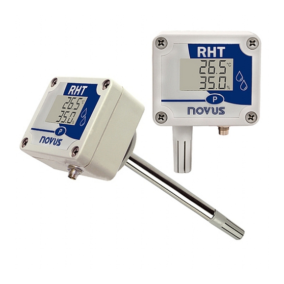
The following elements are located at the front side of the transmitter:
Fig. 1 – Transmitter front
Communication Indicator (COM): Indicates when the device is receiving
data from the Modbus network.
Button
(Programming): Button used for configuration of the
communication parameters and for screen changing.
Temperature: Value of measured temperature.
Relative Humidity: Value of measured relative humidity.
Fig. 2 – Second transmitter screen
Communication Address: Value programmed for identifying the transmitter
of the Modbus network. Programmable between 1 and 247.
NOVUS AUTOMATION
RHT-P10-485-LCD
and
2
SPECIFICATIONS
From -40 °C to 70 °C
Operating temperature of
the transmitter
Sensor and Rod (RHT-DM): See Fig. 3.
Electromagnetic
EM 61326:2000
compatibility
Temperature: -40.0 °C to 100.0 °C.
Sensor measuring
Relative Humidity (RH): 0.0 to 100.0 % RH.
range
Dew Point: -40.0 °C and 100.0 °C
See Fig. 3.
Measurement accuracy
Note: a small measurement error can be
eliminated adjusting the OFFSET parameter of
the software.
Temperature: 0.1 °C.
14 bits (16383 levels)
Measuring resolution
Relative Humidity (RH): 0.1 %.
12 bits (4095 levels)
Temperature: up to 30 s in slow air movement.
Response time
Humidity: up to 8 s in smooth air movement
Sampling interval
3 seconds
Power supply
12 Vdc to 30 Vdc, consumption < 16 mA
Housing
Polycarbonate
Product appropriate for applications which
require protection class up to IP65.
Protection class
Electronic module case: IP65; Sensor
capsule: IP40
Dimensions
60 x 70 x 35 mm
Configuration Software for Windows 98, NT,
2000, XP and Vista.
DigiConfig software
Menus in Portuguese, English or Spanish.
operation environment
Configures, reads and exhibits data on the
screen.
1.5 m long communication cable is part of the
Accessories
product or can be purchased separately (PN:
8813099999).
(No Condensing)
(20 to 80 % RH).
1/6
Advertisement
Table of Contents

Related Manuals for Novus RHT-WM-485-LCD


Summary of Contents for Novus RHT-WM-485-LCD
-
Page 1: Specifications
The identification label is fixed on the transmitter body. Check if the features described on this label are in accordance with your order. See Fig. 3. The RHT-WM-485-LCD and RHT-P10-485-LCD models intended for wall mounting, while the RHT-DM-485-LCD model comes with a probe tip rod for Measurement accuracy Note: a small measurement error can be installation in ducts or through walls. -
Page 2: Mechanical Installation
The probe is made in stainless steel, with standard lengths of 150 mm or 250 mm. Fig. 6 - Fixing bores and dimensions of the RHT-WM-485-LCD model Fig. 5 – Dimensions of the RHT-DM-485-LCD model Fig. 7 – Dimensions of the RHT-WM-485-LCD model... -
Page 3: Electrical Installation
RHT-WM-485-LCD, RHT-DM-485-LCD and RHT-P10-485-LCD Transmitters The RHT-P10-485-LCD electronic housing is designed for wall mounting, Be careful when connecting the power supply wires to the while its remote sensor probe is intended for inserting and screwing in a RHT-WM-485-LCD, RHT-DM-485-LCD and RHT-P10-485- flange. -
Page 4: Serial Communication
RHT-WM-485-LCD, RHT-DM-485-LCD and RHT-P10-485-LCD Transmitters READ HOLDING REGISTERS – 0x03 This command can be used for reading the value of one or several holding registers, according to the “Holding Registers Table”. 4ª Screen: Parity WRITE HOLDING REGISTERS – 0x06 Read-only screens of the values measured by the transmitter: This command can be used for writing in a holding register, according to the “Holding Registers Table”. - Page 5 RHT-WM-485-LCD, RHT-DM-485-LCD and RHT-P10-485-LCD Transmitters HOLDING REGISTERS TABLE The specified addresses correspond to the low-level physical addresses, where zero (0) corresponds to the PLC 40001 address. The minimum and maximum columns show the range of values valid for each parameter. The R/W column indicates if the parameter is for reading and writing (R/W) or for reading only (R).
- Page 6 RHT-WM-485-LCD, RHT-DM-485-LCD and RHT-P10-485-LCD Transmitters TAKING CARE WITH THE SENSORS The calibration of the humidity sensor may be changed if it is exposed to contaminant vapors or extreme humidity and temperature conditions for long time periods. For accelerating the calibration recovery follow the procedure as described below: •...
Need help?
Do you have a question about the RHT-WM-485-LCD and is the answer not in the manual?
Questions and answers