Advertisement
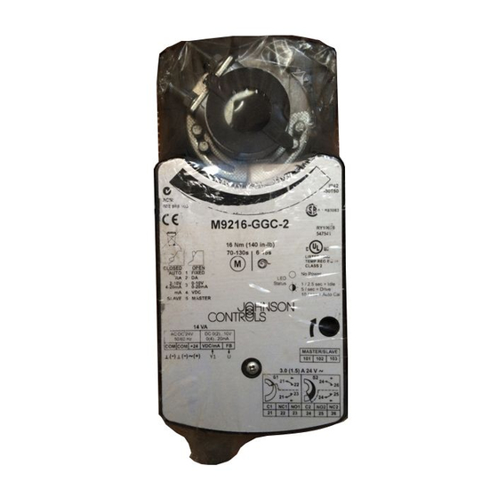
M9216 Series Electric Spring Return Actuators
Installation
IMPORTANT: The M9216 Series actuator is
intended to control equipment under normal
operating conditions. Where failure or malfunction of
an M9216 actuator could lead to an abnormal
operating condition that could cause personal injury
or damage to the equipment or other property, other
devices (limit or safety controls) or systems (alarm or
supervisory) intended to warn of, or protect against,
failure or malfunction of an M9216 actuator must be
incorporated into and maintained as part of the
control system.
Parts Included
•
M9216 actuator
•
M9000-100 NPT conduit adaptor and nut
(two included for actuators with switches or a
feedback potentiometer)
•
M9000-160 anti-rotation bracket
•
two No. 12-24 x 1/2 in. self-tapping hex
washer-head screws
•
5 mm manual crank
For GGA models:
•
one M9000-106 pluggable 4-terminal block
For GGC models:
•
two M9000-105 pluggable 3-terminal blocks
•
one M9000-106 pluggable 4-terminal block
© 2017 Johnson Controls
Part No. 34-636-461, Rev. J
*34636461G*
34-636-461, Rev. J
Installation Instructions
Special Tools Needed
•
Drill with a 3/16 in. (No. 15, 4.57 mm) drill bit
•
Torque wrench with 10 mm socket
•
7 mm and 5/16 in. (8 mm) nut driver
•
Digital voltmeter
Spring Return Direction
The actuator is factory set to spring return in a
Counterclockwise (CCW) direction.
Clockwise (CW)
To change the spring return direction to CW, refer to
Figure 1 and proceed as follows:
1. Turn the actuator over. Use a flat-blade
screwdriver to release the locking clip, and remove
it from the coupler.
2. Remove the coupler and sleeve from the front of
the actuator, and slide the sleeve off the coupler.
Locking
Clip
Back of
the Actuator
Figure 1: Changing the Spring Return Direction
M9216
Issue Date
October 2017
Limit
Stop
Tab
Sleeve
Position
Groove
Indicator
for the
Locking Clip
www.johnsoncontrols.com
1
Advertisement
Table of Contents

Subscribe to Our Youtube Channel
Related Manuals for Johnson Controls M9216 Series


Summary of Contents for Johnson Controls M9216 Series
- Page 1 *34636461G* 34-636-461, Rev. J Installation Instructions M9216 Issue Date October 2017 M9216 Series Electric Spring Return Actuators Installation IMPORTANT: The M9216 Series actuator is Special Tools Needed intended to control equipment under normal • Drill with a 3/16 in. (No. 15, 4.57 mm) drill bit operating conditions.
- Page 2 Note: “A” is the distance from the center of 4. Repeat Steps 4, 5, and 6 of the previous section. the holes in the anti-rotation bracket to the center of the shaft. (See Table 1.) Figure 3: Mounting Positions M9216 Series Electric Spring Return Actuators Installation Instructions...
- Page 3 Table 1 and Figure 3). Limit Stop Note: When installing the actuator to a (Increments correspond Johnson Controls damper, use the existing holes in the to those on damper frame. the opposite side.) 4. Attach the anti-rotation bracket to the damper...
- Page 4 0-10 V or 2-10 V is available on GGx, HGx, and JGx models. 0-135 ohms feedback is available on AGD models and (Ω is ohms.) 0 to 1000 ohms feedback on AGE models. . Figure 6: Nominal Feedback Signal Relative to the Rotation Range M9216 Series Electric Spring Return Actuators Installation Instructions...
-
Page 5: Terminal Block
Figure 8. 2. Push the plastic plug out of the conduit opening with fingertip. M9216 Series Electric Spring Return Actuators Installation Instructions... - Page 6 Slave Master 1 Common 2 Common Terminal Block 2, 3 Power Auxiliary Switches for 4 Control Signal GGC (See Figure 8.) 5 Feedback Output Figure 12: Mode Switch Settings for GGx Models M9216 Series Electric Spring Return Actuators Installation Instructions...
-
Page 7: Setup And Adjustments
Reverse the control wiring connections at Terminals 3 unit according to the action and signal range and 4 to select RA operation for the floating models. desired. (Refer to the Calibration section.) (See Terminal Block 1 in Figure 8.) M9216 Series Electric Spring Return Actuators Installation Instructions... - Page 8 (The feedback output remains 0 to 10 VDC, 4. Connect Terminals 1 and 3 to a voltmeter to unless Mode Switch 3 is positioned for 2 to 10 VDC.) monitor the calibration output. M9216 Series Electric Spring Return Actuators Installation Instructions...
-
Page 9: Repairs And Replacement
Repairs and Replacement Field repairs must not be made. For a replacement or an accessory, refer to the Ordering Information section in the M9216 Series Electric Spring Return Actuators Product Bulletin (LIT-2681068). M9216 Series Electric Spring Return Actuators Installation Instructions... -
Page 10: Technical Data
The performance specifications are nominal and conform to acceptable industry standards. For application at conditions beyond these specifications, consult the local Johnson Controls office. Johnson Controls shall not be liable for damages resulting from misapplication or misuse of its products.
Need help?
Do you have a question about the M9216 Series and is the answer not in the manual?
Questions and answers