
Related Manuals for Johnson Controls LP-NRM653-000C


Summary of Contents for Johnson Controls LP-NRM653-000C
- Page 1 Network Room Modules Installation Guide Part No. 24-85638-1214, Rev. E Issue Date June 14, 2010 Network Room Modules...
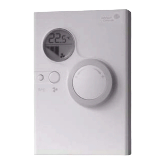
- Page 2 25 (0.98) 80 (3.15) 35 (1.38) 80 (3.15) LCD Display Dial for Temperature with back-light Setpoint Adjustment 120 (4.72) Display in Celsius and Fahrenheit units Figure 1: Dimensions, mm (in.)
- Page 3 Figure 2: Removing the Cover from the Base...
- Page 4 60 (2.36) 31 (1.22) 4,3 (0.17) 2 x Ø 4.2 (0.16) 29 (1.14) 33 (1.30) 33 (1.30) 38 (1.50) Figure 3: Wall Mounting Base Dimensions, mm (in.)
- Page 5 Figure 4: Dual-Switch DIP Switch Block Figure 5: Terminal Block Connection...
- Page 6 Figure 6: Service Port (4-pin) for LP-NRM0xx-000C Series Figure 7: Port (6-pin Modular Jack) for LP-NRM5xx-000C and LP-NRM6xx-000C Series...
-
Page 7: General Features
CAREFULLY BEFORE INSTALLING, AND SAVE IT FOR FUTURE USE General Features • Network Room Modules (NRMs) are designed for use with Johnson Controls® Facility Explorer FX06, FX07, FX14, and FXVMA Field Controllers. • The Liquid Crystal Display (LCD), along with a dial and push button(s) on... - Page 8 • Flat-head screwdrivers, 3 mm and 5 mm (1/8 to 5/32 in.) • Drill, bits, and appropriate 4 mm (3/16 in.) screws and plugs • Pointed tool (available from Johnson Controls, Ordering Code TM-9100-8900 in Europe, or T-4000-119 in North America) Figure 1: Dimensions, mm (in.)
- Page 9 Figure 2: Removing the Cover from the Base 1. Remove the retaining screw (if inserted) from the top of the module enclosure. 2. Remove the module cover from the base by inserting a pointed tool into the narrow slot at the center top of the cover. While pressing down gently, pry the base away from the cover.
- Page 10 IMPORTANT: The installation of electrical wiring must conform to local codes and should be carried out by authorized personnel only. Users should ensure that all Johnson Controls products are used safely and without risk to health or property. Network Room Modules Installation Guide...
-
Page 11: Service Port
Figure 5: Terminal Block Connection • Terminations are made on the terminal block in the base of the module, which is accessible after removing the cover from the base. • The screw terminals accept up to 1.5 mm (16 AWG) wires. •... -
Page 12: Ordering Codes
LP-NRM511-000C LP-NRM502-000C LP-NRM503-000C Table 3: Network Room Modules (Available in North America) Product Code Features/Options LP-NRM511-000C 80 x 80 LP-NRM552-000C (3.15 x LP-NRM553-000C 3.15 in.) LP-NRM611-000C 120 x 80 LP-NRM652-000C (4.72 x LP-NRM653-000C 3.15 in.) Network Room Modules Installation Guide... - Page 13 Table 4: NRM Mounting Kits and Accessories Ordering Codes Description TM-1100-8931 Plastic Base for Surface Mounting - White TM-9100-8941-W Recessed Wall Box Mounting Kit - White TM-9100-8951-W Panel Mounting Kit - White NS-WALLPLATE-0 Wall plate kit used to mount an 80 x 80 mm (3.15 x 3.15 in.) NRM onto a 2 x 4 in.
-
Page 14: Technical Specifications
Technical Specifications NRM Technical Specifications (Part 1 of 2) Product Network Room Module Power Requirements 14.3 to 27.6 VDC at 500 mW maximum or LP-NRM0xx-000C 24 VAC ±15%, 50/60 Hz, Series at 1 VA maximum Class 2 or Safety Extra-Low Voltage (SELV) Power Requirements 9.8 to 16.5 VDC (15 VDC nominal) LP-NRM5xx-000C and... - Page 15 FX14, V 2.32 and higher FXVMA, all versions Compliance Europe CE Mark – Johnson Controls, Inc., declares that the Network Room Modules (NRMs) are in compliance with the essential requirements and other relevant provisions of the EMC Directive 2004/108/EC. Canada UL Listed (PAZX7), C22.2 No.
- Page 16 Network Room Modules Installation Guide...
- Page 17 Building Efficiency 507 E. Michigan Street, Milwaukee, WI 53202 Johnson Controls® is a registered trademark of Johnson Controls, Inc. All other marks herein are the marks of their respective owners. © 2010 Johnson Controls, Inc.
Need help?
Do you have a question about the LP-NRM653-000C and is the answer not in the manual?
Questions and answers