Roger Technology B70/1DCHP Instructions And Warnings For Installation
Hide thumbs
Also See for B70/1DCHP:
- Instruction and warnings for the installer (236 pages) ,
- Quick start (5 pages) ,
- Instruction and warnings for the installer (40 pages)
Advertisement
Available languages
Available languages
Quick Links
FW
P2.00
IS142 Rev.09 09/03/2021
B70/1DCHP
centrale di comando 36Vdc per cancelli scorrevoli
Istruzioni originali
IT -
Istruzioni ed avvertenze per l'installatore
EN -
Instructions and warnings for the installer
DE -
Anweisungen und Hinweise für den Installateur
FR -
Instructions et consignes pour l'installateur
ES -
Instrucciones y advertencias para el instalador
PT -
Instruções e advertências para o instalado
NL -
Aanwijzingen en waarschuwingen voor de installateur
PL -
Advertisement
Chapters

Related Manuals for Roger Technology B70/1DCHP


Summary of Contents for Roger Technology B70/1DCHP
- Page 1 P2.00 IS142 Rev.09 09/03/2021 B70/1DCHP centrale di comando 36Vdc per cancelli scorrevoli Istruzioni originali IT - Istruzioni ed avvertenze per l’installatore EN - Instructions and warnings for the installer DE - Anweisungen und Hinweise für den Installateur FR - Instructions et consignes pour l’installateur...
-
Page 3: Table Of Contents
INDICE • INDEX • INDEX • INDEXER • ÍNDICE • ÍNDICE • INDEX • INDEKS ITALIANO DEUTSCH Avvertenze generali Allgemeine Sicherheitshinweise Dichiarazione CE di Conformità Konformitätserklärung Simbologia Symbole Descrizione prodotto Produktbeschreibung Aggiornamenti versione P2.00 Aktualisierungen Version P2.00 Caratteristiche tecniche prodotto Technische Daten des Produkts Descrizione dei collegamenti Beschreibung der Anschlüsse... - Page 4 ESPAÑOL DUTCH Advertencias generales Algemene waarschuwingen Declaración CE de Conformidad EG-verklaring van overeenstemming Símbolos Symbolen Descripción del producto Beschrijving product Actualización de la versión P2.00 Update versie P2.00 Características técnicas del producto Technische kenmerken product Descripción de las conexiones Beschrijving aansluitingen Instalación básica Type installatie Conexiones eléctricas...
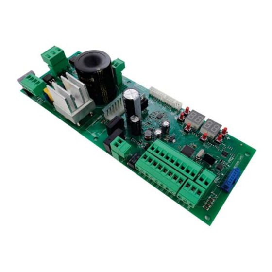
- Page 5 P2.00 Connettori di collegamento encoder, Plug for encoder, limit switch and unlock microswitch connection Connettore scheda carica Display a 4 cifre e 6 tasti di Collegamento batterie batterie programmazione Batteries connection Plug for battery charger 4 digit display and 6 programming buttons Microcontrollore Collegamento...
- Page 7 FUSIBILE FUSE FUSIBILE FUSE FUSIBILE FUSE Alimentazione Power supply BATTERY CHARGER +LAM +24V COS2 COS1 H93/RX22A/I RICEVITORE RADIO RADIO RECEIVER...
- Page 8 Luce di cortesia Courtesy light 230Vac 100W marrone brown blue marrone brown FUSIBILE FUSE max 1A +LAM Spia cancello aperto Lampeggiante Open gate light Flashing light 24Vdc 3W 24Vdc max 25W +24V Apertura parziale Partial opening COS2 Passo passo Bordo sensibile 2 Step by step Safety edge 2 COS1...
- Page 9 COLLEGAMENTO CON 1 COPPIA FOTOCELLULE SINCRONIZZATE (MODALITÁ NORMALE, SOLO COPPIA MASTER) CONNECTION WITH 1 SYNCHRONISED PHOTOCELL PAIR (NORMAL MODE, MASTER PAIR ONLY) ROSSO = libero da jumper RED = jumper free JUMPER DI SINCRONIZZAZIONE (PER MASTER) SYNCHRONISATION JUMPER (FOR MASTER) 1 2 3 1 2 3 JUMPER DI ALLINEAMENTO...
- Page 10 COLLEGAMENTO CON 2 COPPIE FOTOCELLULE SINCRONIZZATE (MODALITÁ NORMALE, 1 MASTER E 1 SLAVE) CONNECTION WITH 2 SYNCHRONISED PHOTOCELL PAIRS (NORMAL MODE, 1 MASTER AND 1 SLAVE) ROSSO = libero da jumper RED = jumper free JUMPER DI SINCRONIZZAZIONE (PER MASTER) SYNCHRONISATION JUMPER 1 2 3 1 2 3...
- Page 11 TEST FOTOCELLULE · PHOTOCELLS TEST ( COLLEGAMENTO CON 1 COPPIA FOTOCELLULE SINCRONIZZATE (MODALITÁ NORMALE, SOLO COPPIA MASTER) CONNECTION WITH 1 SYNCHRONISED PHOTOCELL PAIR (NORMAL MODE, MASTER PAIR ONLY) ROSSO = libero da jumper RED = jumper free JUMPER DI SINCRONIZZAZIONE (PER MASTER) SYNCHRONISATION JUMPER (FOR MASTER)
- Page 12 TEST FOTOCELLULE · PHOTOCELLS TEST ( COLLEGAMENTO CON 2 COPPIE FOTOCELLULE SINCRONIZZATE (MODALITÁ NORMALE, 1 MASTER E 1 SLAVE) CONNECTION WITH 2 SYNCHRONISED PHOTOCELL PAIRS (NORMAL MODE, 1 MASTER AND 1 SLAVE) ROSSO = libero da jumper RED = jumper free JUMPER DI SINCRONIZZAZIONE (PER MASTER) SYNCHRONISATION JUMPER...
- Page 13 BATTERY SAVING ( BATTERY SAVING + TEST FOTOCELLULE · PHOTOCELLS TEST ( COLLEGAMENTO CON 1 COPPIA FOTOCELLULE SINCRONIZZATE (MODALITÁ NORMALE, SOLO COPPIA MASTER) CONNECTION WITH 1 SYNCHRONISED PHOTOCELL PAIR (NORMAL MODE, MASTER PAIR ONLY) ROSSO = libero da jumper RED = jumper free JUMPER DI SINCRONIZZAZIONE (PER MASTER) SYNCHRONISATION JUMPER...
- Page 14 BATTERY SAVING ( BATTERY SAVING + TEST FOTOCELLULE · PHOTOCELLS TEST ( COLLEGAMENTO CON 2 COPPIE FOTOCELLULE SINCRONIZZATE (MODALITÁ NORMALE, 1 MASTER E 1 SLAVE) CONNECTION WITH 2 SYNCHRONISED PHOTOCELL PAIRS (NORMAL MODE, 1 MASTER AND 1 SLAVE) ROSSO = libero da jumper RED = jumper free JUMPER DI SINCRONIZZAZIONE (PER MASTER)
- Page 15 PR1 PR2...
- Page 16 Nero/Black (26 Vac) Blu/Blue (19 Vac)
- Page 17 BG30 High Speed Cavo motore Motor cable B72/BRAKE2...
- Page 18 FINECORSA MECCANICO MECHANICAL LIMIT SWITCH FINECORSA MAGNETICO MAGNETIC LIMIT SWITCH...
- Page 19 BATTERY B71/BCHP BATTERY CHARGER BATTERY FC SB PROG TEST 10 11 12 13 14 15 16 17 18 SEC2 SEC1 TRANSFORMER BLACK FUSE T10A 5x20 2 x 12V 4,5Ah AGM Battery ONLY...
-
Page 20: Avvertenze Generali
La mancata osservanza delle informazioni contenute nel presente manuale può dare luogo a infortuni personali o danni all’apparecchio. ROGER TECHNOLOGY declina qualsiasi responsabilità derivante da un uso L’installazione, i collegamenti elettrici e le regolazioni devono essere effettuati da norme vigenti. - Page 21 EN 12453 e EN 12445. ROGER TECHNOLOGY declina ogni responsabilità qualora vengano installati In caso sia attiva la funzione uomo presente dovrà essere cura dell’installatore deformabile in gomma, la velocità di chiusura del varco ed in generale tutti gli e il funzionamento dell’automazione e che il tipo di comando ed il tipo di utilizzo...
-
Page 22: Dichiarazione Ce Di Conformità
Dichiarazione CE di Conformità Il sottoscritto Dino Florian, legale rappresentante di Roger Technology - Via Botticelli 8, 31021 Mogliano V.to (TV) DICHIARA che la centrale di comando B70/1DCHP stabilite dalle seguenti direttive CE: – 2014/35/EU Direttiva LVD –... -
Page 23: Simbologia
22. Descrizione prodotto La centrale di comando digitale B70/1DCHP a 36 V utilizza il controllo di potenza motore in modalità sensored, avvalendosi di un encoder ad alta risoluzione, per gestire le automazioni ROGER Brushless per un’anta scorrevole. Attenzione all’impostazione del parametro A1. Una errata impostazione può causare anomalie nel funzionamento dell’automazione. -
Page 24: Aggiornamenti Versione P2.00
I dati sono garantiti SOLO con accessori originali ROGER TECHNOLOGY. L'utilizzo di accessori non originali può causare malfunzionamenti. ROGER TECHNOLOGY declina ogni responsabilità per installazioni errate o non conformi. Tutti i collegamenti sono protetti da fusibili, vedi tabella. La luce di cortesia necessita di un... -
Page 25: Descrizione Dei Collegamenti
Descrizione dei collegamenti Installazione tipo loro caratteristiche tecniche. Cavo consigliato Alimentazione di rete. Cavo a doppio isolamento tipo H07RN-F 3x1,5 mm Fotocellula - Ricevitore F4ES/F4S Cavo 5x0,5 mm (massimo 20 m) Fotocellula - Trasmettitore F4ES/F4S Cavo 3x0,5 mm (massimo 20 m) Lampeggiante a LED R92/LED24 - FIFTHY/24 Cavo 2x1 mm (massimo 10 m) -
Page 26: Collegamenti Elettrici
±10%) Fusibile 5x20 T2A. Ingresso secondario del trasformatore per alimentazione motore 26 Vac (SEC1) e per alimentazione logica e periferiche 19 Vac (SEC2). NOTA: Il cablaggio è realizzato di fabbrica da ROGER TECHNOLOGY. SEC2 SEC1 X-Y-Z Collegamento al motore ROGER Brushless. -
Page 27: Comandi E Accessori
Comandi e accessori Le sicurezze con contatto N.C., se non installate devono essere ponticellate ai morsetti COM, oppure disabilitate modificando i parametri LEGENDA: N.A. (Normalmente Aperto) . N.C. (Normalmente Chiuso). CONTATTO DESCRIZIONE 9(COR) Collegamento luce di cortesia (contatto puro) 230 Vac 100 W - 24 Vac/dc 40 W. NOTA: Prevedere un fusibile a protezione. - Page 28 CONTATTO DESCRIZIONE 25(AP) 23(COM) Ingresso comando di apertura (N.A.). ATTENZIONE: l'attivazione persistente del comando di apertura non permette la richiusura automa- tica; il conteggio del tempo di richiusura automatica riprende al rilascio del comando di apertura. 26(CH) 23(COM) Ingresso comando di chiusura (N.A.). 27(PP) 23(COM) Ingresso comando passo-passo (N.A.).
-
Page 29: Tasti Funzione E Display
Tasti funzione e display TASTO DESCRIZIONE Parametro successivo Parametro precedente DOWN Incremento di 1 del valore del parametro DOWN Decremento di 1 del valore del parametro PROG Apprendimento della corsa PROG TEST TEST Attivazione modalità TEST • Premere i tasti UP e/o DOWN •... -
Page 30: Modalità Visualizzazione Di Stato Comandi E Sicurezze
10.2 Modalità visualizzazione di stato comandi e sicurezze STATO DEI COMANDI STATO DELLE SICUREZZE COS1 COS2 POWER STOP STATO DEI COMANDI: Le indicazioni dei comandi sono normalmente SPENTE. Si ACCENDONO alla ricezione di un comando (esempio: quando viene dato un comando di passo-passo si accende il segmento PP). -
Page 31: Modalità Test
10.3 Modalità TEST provoca uno STOP. La successiva pressione abilita la modalità di TEST. Il lampeggiante e la spia cancello aperto si accendono per un secondo. Il display visualizza a sinistra, per 5 s, lo stato dei comandi SOLO se attivi, (AP, CH, PP, PE, OR). -
Page 32: Apprendimento Della Corsa
Apprendimento della corsa 11.1 Prima di procedere 1. Selezionare il modello dell’automazione installata con il parametro LEGENDA: Motore HIGH SPEED Motore REVERSIBILE TIPO SELEZIONE MODELLO CONFIGURAZIONI MOTORE BG30/1600 BG30/2200 Vedi capitolo 14 "Parametri speciali per BG30/1000/HS High Speed" Vedi capitolo 15 "Parametri speciali BG30/1400/R motori Reversibili"... -
Page 33: Procedura Di Apprendimento
TEST VEDI CAPITOLO 16 e 17 1 click finchè ... TEST PROG VEDI PROCEDURA DI TEST AP P- APPRENDIMENTO CAP. 11.2 1 click CHIUSO 1 click Tener premuto Sì TEST VEDI PROCEDURA DI APPRENDIMENTO CAP. 11.2 1 click 11.2 Procedura di apprendimento PROG FO FO TO TO AP P-... -
Page 34: Indice Dei Parametri
Indice dei parametri PARAM. VALORE DI DESCRIZIONE PAGINA FABBRICA vedi Cap. 13 Selezione modello automazione Richiusura automatica dopo il tempo di pausa (da cancello completamente aperto) Richiusura automatica dopo interruzione di alimentazione di rete (black-out) Selezione funzionamento comando passo-passo (PP) Prelampeggio Funzione condominiale sul comando di apertura parziale (PED) Abilitazione funzione a uomo presente... - Page 35 PARAM. VALORE DI DESCRIZIONE PAGINA FABBRICA Selezione della posizione di installazione del motore rispetto al varco, vista lato interno Selezione modalità di funzionamento luci di cortesia Abilitazione della chiusura/apertura garantita Regolazione tempo di attivazione della chiusura/apertura garantita Selezione gestione funzionamento a batteria Selezione delle limitazioni nel funzionamento a batteria Selezione del tipo di batteria e riduzione dei consumi Ripristino ai valori standard di fabbrica...
-
Page 36: Menù Parametri
Menù parametri VALORE DEL PARAMETRO PARAMETRO Selezione modello automazione ATTENZIONE! Una errata impostazione può causare anomalie nel funzionamento dell’automazione. NOTA: nel caso di ripristino ai parametri standard di fabbrica, il valore del parametro deve essere reimpostato manualmente. BG30/1600 - Motore IRREVERSIBILE per anta da 1600 kg max. BG30/2200 - Motore IRREVERSIBILE per anta da 2200 kg max. - Page 37 Funzione condominiale sul comando di apertura parziale (PED) Disabilitato. Il cancello si apre parzialmente in modalità passo-passo: apre-stop-chiude-stop-apre... Abilitato. Durante l’apertura il comando di apertura parziale (PED) viene ignorato. Abilitazione funzione a uomo presente Disabilitato. Abilitato. Il cancello funziona tenendo premuti i comandi apre (AP) o chiude (CH). Al rilascio del comando il cancello si ferma.
- Page 38 Abilitazione gestione apertura con esclusione della richiusura automatica Se abilitata, l'esclusione della richiusura automatica vale solo per il comando selezionato dal parametro. Esempio: se si imposta automatica si attiva. NOTA: Il comando ha funzione di attivazione in sequenza apre-stop-chiude oppure chiude-stop-apre. Disabilitata.
- Page 39 Regolazione della coppia motore durante la fase di recupero posizione Regolare con il parametro la coppia motore se in fase di recupero posizione i valori impostati ai parametri fossero inadeguati per garantire al cancello di completare la manovra. Se la fase di recupero posizione non si completa, il cancello non riprende il suo normale funzionamento. e dal valore di corrente massi- ma memorizzata in fase di apprendimento della corsa.
- Page 40 Impostazione modalità di funzionamento della fotocellula in apertura (FT2) INVERSIONE IMMEDIATA. Se si attiva la fotocellula durante la manovra di apertura, il cancello inverte immediatamente. ad aprire. INVERSIONE RITARDATA. Con fotocellula oscurata il cancello si ferma. Liberata la fotocellula il cancello chiude. Impostazione modalità...
- Page 41 NOTA: Con ricevitore radio ROGER TECHNOLOGY ad innesto. NOTA: Con ricevitore radio ROGER TECHNOLOGY ad innesto. PASSO PASSO. APERTURA PARZIALE. APERTURA. CHIUSURA. STOP. parametro viene ignorato. Luce di cortesia passo-passo (PP). L’uscita COR viene gestita dal radiocomando. Il radiocomando accende-spegne la luce di cortesia. Il parametro viene ignorato.
- Page 42 Regolazione tempo di attivazione della chiusura/apertura garantita NOTA: Da 2 a 90 s di attesa. Da 2 a 9 min di attesa. Selezione gestione funzionamento a batteria Impostando un valore diverso da il tipo di funzionalità desiderata al parametro e abilitare una segnalazione mediante l’uscita COR al parametro Il controllo si attiva quando la tensione di batteria scende alla soglia minima (22Vdc per batteria 2x12Vdc) Il controllo si attiva quando la tensione di batteria scende alla soglia intermedia (23Vdc per batteria 2x12Vdc) Il controllo si attiva quando la tensione di batteria scende alla soglia massima (24Vdc per batteria 2x12Vdc)
- Page 43 NOTA: i valori indicati in tabella sono valori puramente indicativi. Versione HW Anno di produzione Settimana di produzione Esempio: Numero seriale Versione FW Visualizzazione contatore manovre moltiplicato per 100. NOTA: i valori indicati in tabella sono valori puramente indicativi. Manovre eseguite Esempio: x100 = 1.234.500 manovre Visualizzazione contatore ore manovra...
-
Page 44: Parametri Speciali Serie High Speed
Parametri speciali serie HIGH SPEED La serie BG30/HS (High Speed) rappresenta la linea degli operatori scorrevoli digitali Brushless ad alta residenziale e industriale. La tecnologia High Speed consente di gestire l'automazione al 100% più velocemente delle automazioni tradizionali con la possibilità di gestire separatamente velocità, accelerazione, rallentamenti e relative sicurezze. NOTA: Non conoscendo la meccanica del cancello, per garantire la massima sicurezza dell'impianto, si consiglia l'uso di bordi sensibili. -
Page 45: Parametri Speciali Serie Bg30/1400/R
Parametri speciali serie BG30/1400/R La serie BG30/R (REVERSIBILE) rappresenta la linea degli operatori scorrevoli digitali Brushless per i La tecnologia REVERSIBILE consente di aprire e chiudere il cancello, anche in assenza di tensione, senza sbloccare il motore. La centrale permette di gestire separatamente velocità, accelerazione, rallentamenti e relative sicurezze. -
Page 46: Segnalazione Degli Ingressi Di Sicurezza E Dei Comandi (Modalità Test)
Segnalazione degli ingressi di sicurezza e dei comandi (modalità TEST) DISPLAY POSSIBILE CAUSA INTERVENTO DA SOFTWARE INTERVENTO TRADIZIONALE Chiudere la maniglia di sblocco e girare la chiave in posizione di chiusura. (Sb) sblocco. Contatto STOP di sicurezza Installare un pulsante di STOP (N.C.) aperto. -
Page 47: Segnalazione Allarmi E Anomalie
Segnalazione allarmi e anomalie SEGNALAZIONE PROBLEMA POSSIBILE CAUSA INTERVENTO ALLARME LED POWER spento Manca alimentazione. LED POWER spento Fusibili bruciati. Sostituire il fusibile. Si raccomanda di estrarre e reinserire il fusibile sola- mente in assenza di tensione di rete. Anomalia nella tensione di Togliere alimentazione, attendere 10 s e ridare alimen- alimentazione di ingresso. - Page 48 SEGNALAZIONE PROBLEMA POSSIBILE CAUSA INTERVENTO ALLARME Malfunzionamento Premere il tasto TEST, se la segnalazione di errore per- dell’encoder. siste, sostituire l’encoder. (EnE5) Alimentazione da rete in- Nel caso ci sia presenza di sporco, umidità, insetti o al- tro, togliere l’alimentazione e pulire l'encoder e la sche- da.
-
Page 49: Diagnostica - Modalità Info
DALLA MODALITA’ x5 s La Modalità INFO permette di visualizzare alcuni valori misurati dalla centrale B70/1DCHP. Dalla modalità “Visualizzazione comandi e sicurezze” e con motore fermo, premere per 5 s il tasto TEST. La centrale visualizza in sequenza i seguenti parametri e il valore rilevato corrispondente: Parametro Funzione (esempio: . -
Page 50: Sblocco Meccanico
Sblocco meccanico Per ulteriori informazioni consultare l'operazione di blocco/sblocco sul manuale d'uso dell'automazione. Se si sblocca il cancello con la centralina alimentata, sul display appare lampeggiante. ricevimento di un comando, avvia una procedura di recupero posizione (vedi capitolo 20). Modalità di recupero posizione completamente chiuso, la centralina al ricevimento di un comando avvia una procedura di recupero posizione: •... -
Page 51: Messa In Funzione
Informazioni aggiuntive e contatti Tutti i diritti relativi alla presente pubblicazione sono di proprietà esclusiva di ROGER TECHNOLOGY. Il formato digitale (PDF) e tutti gli eventuali aggiornamenti futuri, sono disponibili nell’area riservata del nostro sito internet www.rogertechnology.com/B2B nella sezione Self Service. -
Page 52: General Safety Precautions
ROGER TECHNOLOGY is not liable for failure to observe the good practices in during use. The safety devices (photocells, sensing edges, emergency stops, etc.) must be... - Page 53 The installer is required to measure impact forces and select on the control unit the appropriate speed and torque values to ensure that the door or gate ROGER TECHNOLOGY cannot be held responsible for any damage or injury caused by the installation of incompatible components which compromise the safety and correct operation of the device.
-
Page 54: Declaration Ce Of Conformity
Declaration CE of Conformity The undersigned Dino Florian, legal representative of Roger Technology - Via Botticelli 8, 31021 Mogliano V.to (TV) DECLARES that the B70/1DCHP digital control unit is compliant with the provisions established by Community directives: – 2014/35/EU LVD Standard –... -
Page 55: Symbols
22. Product description The B70/1DCHP 36 V digital control unit uses a high resolution encoder for the sensored power control of ROGER sliding gate leaf automation systems. Ensure that the parameter A1 is set correctly. If this parameter is not set correctly, the automation system may not function properly. -
Page 56: Updates Of Version P2.00
The total of the absorption values of all the accessories connected must not exceed the maximum power values shown in the table. The values are guaranteed with original ROGER TECHNOLOGY accessories ONLY. The use of non-original accessories may lead to malfunctioning. ROGER TECHNOLOGY declines all responsibility for incorrect or non-conforming installations. -
Page 57: Description Of Connections
Description of connections To access the control connection terminal board, remove the motor cover as shown in Figure 2-3-4-5 shows connection diagrams for connecting mains voltage to the motor control unit Typical installation It is the installer's responsibility to verify the adequacy of the cables in relation to the devices used in the installation and their technical characteristics. -
Page 58: Electrical Connections
Measure the voltage on the primary mains power connection with a tester. TRANSFORMER For the Brushless automation system to function correctly, the mains power voltage must be: - 230Vac ±10% for the B70/1DCHP control unit. 220÷230 - 115Vac ±10% for the B70/1DCHP/115 control unit. -COM... -
Page 59: Commands And Accessories
16(COM) STOP command input (NC). The current manoeuvre is arrested if the safety contact opens. N.B.: the controller is supplied with this contact already jumpered by ROGER TECHNOLOGY. 21(ANT) Antenna connector for slot-in radio receiver board. Use RG58 if an external antenna is used; maximum recommended length: 10 m. - Page 60 Connector for connecting to encoder installed on motor. WARNING! Always disconnect from electrical power before disconnecting or connecting the encoder cable. N.B.: Ready wired in factory by ROGER TECHNOLOGY. Connector (N.C. contacts) for connecting mechanical limit switch (see - detail B) or mag- netic limit switch (see - detail C).
-
Page 61: Function Buttons And Display
Function buttons and display BUTTON DESCRIPTION Next parameter Previous parameter DOWN Increase value of parameter by 1 DOWN Decrease value of parameter by 1 PROG Travel acquisition PROG TEST TEST Activate TEST mode • Press the UP and/or DOWN buttons to view the parameter you intend to modify. •... -
Page 62: Command And Safety Device Status Display Mode
10.2 Command and safety device status display mode COMMAND STATUS SAFETY DEVICE STATUS COS1 COS2 POWER STOP COMMAND STATUS: The command status indicators on the display are normally OFF. They ILLUMINATE when a command is received (e.g.: when a step mode command is received, the segment PP illuminates). -
Page 63: Test Mode
10.3 TEST mode To activate the mode, press the TEST button with the automatic door system at rest. If the gate is moving, pressing TEST stops the gate. Pressing the button again enables TEST mode. device is activated. The command signal status is shown on the left hand side of the display for 5 seconds, ONLY when the respective command signal is active (AP, CH, PP, PE, OR). -
Page 64: Travel Acquisition
Travel acquisition For the system to function correctly, the gate travel must be acquired by the control. 11.1 Before starting 1. Select the automation system model installed with the parameter KEY: HIGH SPEED Motor REVERSIBLE Motor MOTOR SELECTION MODEL CONFIGURATIONS TYPE BG30/1600 up to 1600 kg... -
Page 65: Acquisition Procedure
TEST SEE CHAPTER 16 and 17 1 click Until ... TEST PROG ACQUISITION TEST AP P- PROCEDURE CHAP. 11.2 1 click CLOSE 1 click Press and hold on TEST ACQUISITION PROCEDURE CHAP. 11.2 1 click 11.2 Acquisition procedure: PROG FO TO AP P- PH A5 PH A5... -
Page 66: Parameter's Index
Parameter's index FACTORY PARAM. DESCRIPTION PAGE VALUE Selecting automation system model see chap. 13 Automatic closure after pause time (from gate completely open) Automatic gate closing after mains power outage Selecting step mode control function (PP) Condominium function for partial open command (PED) Enabling operator present function. - Page 67 FACTORY PARAM. DESCRIPTION PAGE VALUE Selecting courtesy light mode Enable safeguarded gate closure/opening Setting safeguarded closure/opening activation time Selection of the battery operation management Selection of the battery operation limitations Selection of the battery type and consumption reduction Restoring factory default values HW version Year of manufacture Week of manufacture...
-
Page 68: Parameter Menu
Parameter menu PARAMETER PARAMETER VALUE Selecting automation system model WARNING! If this parameter is not set correctly, the automation system may not function properly. N.B.: in the event of a reset to restore the default parameters, this parameter must be set again manually. BG30/1600 - IRREVERSIBLE motor for gate leaves up to 1600 Kg. - Page 69 Condominium function for partial open command (PED) Disabled. The gate opens partially in step mode: open-stop-close-stop-open... Enabled. Partial commands are ignored during gate opening. Enabling operator present function Disabled. Enabled. The open (AP) or close (CH) button must be pressed continuously to operate the gate. The gate stops when the button is released.
- Page 70 Enabling of management for opening with automatic re-closure exclusion If enabled, the exclusion of automatic re-closure only applies for the command selected via the parameter. For example: if you set , automatic re-closure is excluded following an AP command, but it is activated following a PP or PED command.
- Page 71 Setting motor torque during position recovery Adjust motor torque with parameter if, during position recovery, the values set with parameters are insuf- If position recovery is not completed, normal gate operation will not be resumed. The response of the obstacle detection system depends solely on the values set for parameters The response of the obstacle detection system depends on the values set for parameters and on the maxi- mum current value stored during travel acquisition.
- Page 72 Setting photocell mode during gate opening (FT2) DISABLED. Photocell is not active or not installed. STOP. The gate stops and remains stationary until the next command is received. IMMEDIATE REVERSE. The gate reverses immediately if the photocell is activated during gate opening. TEMPORARY STOP.
- Page 73 N.B.: With ROGER TECHNOLOGY plug-in radio receiver board. N.B.: With ROGER TECHNOLOGY plug-in radio receiver board. STEP MODE. PARTIAL OPENING OPENING CLOSING. STOP. Courtesy light. The output COR is managed from the remote control. The light remains lit as long as the remote control is active.
- Page 74 Setting safeguarded closure/opening activation time N.B.: this parameter is not visible if the value of parameter Wait time settable from 2 to 90 s. Wait time settable from 2 to 9 min. Selection of the battery operation management Setting a value different than a battery voltage level check is activated.
- Page 75 N.B.: The values shown in the table are indicative only. HW version. Year of manufacture. Week of manufacture. Example: Serial number. FW version. View manoeuvre counter The number consists of the values of the parameters from multiplied by 100. N.B.: The values shown in the table are indicative only. Manoeuvres performed.
-
Page 76: Special Parameters For High Speed Series
Special parameters for HIGH SPEED series The BG30/HS series (High Speed) is a family of digital brushless high speed sliding motor units for sliding gates weighing up to 1000 kg, 1500 kg or 1800 kg and dedicated exclusively to residential applications. High Speed technology makes it possible for the automation system to operate 100% faster than a conventional system, and allows independent management of speed, acceleration, deceleration and the safety devices used in the system. -
Page 77: Special Parameters For Bg30/1400/R Series
Special parameters for BG30/1400/R series The BG30/R series (REVERSIBLE) is a family of digital brushless motor units for sliding gates weighing up to 1400 kg and dedicated exclusively to residential and industrial applications. REVERSIBLE technology makes it possible to open and close the gate without releasing the motor even in the event of power failure. -
Page 78: Safety Input And Command Status (Test Mode)
Safety input and command status (TEST mode) With no currently active commands, press the TEST button and check the following: DISPLAY POSSIBLE CAUSE ACTION BY SOFTWARE PHYSICAL CORRECTIVE ACTION The release handle is open. Close the release handle and turn the key to the close position. -
Page 79: Alarms And Faults
Alarms and faults PROBLEM ALARM POSSIBLE CAUSE ACTION LED POWER off No power. Check power cable. LED POWER off Fuses blown. Replace fuses. Always disconnect from mains pow- er before removing fuses. Input mains power voltage fault. Disconnect from mains power, wait 10 seconds then reconnect to the mains and switch on. - Page 80 PROBLEM ALARM POSSIBLE CAUSE ACTION Encoder malfunction. Press TEST button. Replace the encoder if the pro- blem persists. (EnE5) If the unit contains dirt, moisture, insects or other foreign matter, disconnect from mains power and clean the board and the encoder. Replace the enco- der if the problem persists.
- Page 81 INFO MODE x5 s INFO mode may be used to view certain parameters measured by the B70/1DCHP controller. Press and hold the TEST button for 5 seconds from the “View command signals and safety devices” mode with the motor stationary.
-
Page 82: Mechanical Release
Mechanical release In the event of a fault or mains power loss, the gate may be released and opened manually. For further information, refer to the locking/release operation in the manual of the automation system. If the gate releases with the controller unit powered, the message When the release system is restored to the normal operating position, if the gate is not completely open or completely closed the next time a command is received, the control initiates a position recovery procedure (see chapter 20). -
Page 83: Start-Up
ROGER TECHNOLOGY is the exclusive proprietor holder of all rights regarding this publication. or any alterations to this document are prohibited without express prior authorised from by ROGER TECHNOLOGY. The digital version of this documentation (in PDF format) and all future revisions are available from the reserved area of our website www.rogertechnology.com/B2B, in the section ‘Self Service’. -
Page 84: Allgemeine Sicherheitshinweise
Die Nichtbeachtung der in diesem Handbuch enthaltenen Informationen kann Verletzungen oder Schäden am Gerät zur Folge haben. ROGER TECHNOLOGY lehnt jede Haftung für Schäden, die durch unsachgemäßen oder nicht bestimmungsgemäßen, den Angaben dieses Handbuchs nicht entsprechenden Gebrauch verursacht werden, ab. - Page 85 Gefahren verursachen. Wenn es aufgrund der Risikoanalyse erforderlich ist, verformbare Sicherheitsleisten am beweglichen Teil installieren. Es ist zu beachten, dass gemäß der Norm UNI EN 12635 alle Anforderungen der Normen EN 12604 und EN 12453 erfüllt und gegebenenfalls auch überprüft werden müssen.
-
Page 86: Konformitätserklärung
Diese Anleitung muss aufbewahrt und eventuellen neuen Benutzern der Anlage übergeben werden. Konformitätserklärung Der Unterzeichnende Dino Florian, gesetzlicher Vertreter von Roger Technology - Via Botticelli 8, 31021 Mogliano V.to (TV) ERKLÄRT, dass die Steuerung B70/1DCHP mit den von den folgenden Gemeinschaftsrichtlinien vorgegebenen Bestimmungen übereinstimmt: –... -
Page 87: Symbole
Symbol für die Entsorgung des Produkts gemäß der WEEE- Richtlinie, siehe Kapitel 22. Produktbeschreibung Die digitale Steuereinheit B70/1DCHP mit 36 V verwendet zur Steuerung des bürstenlosen Motors ROGER für Es muss auf die Einstellung des Parameters A1 geachtet werden. Eine falsche Einstellung kann Funktionsstörungen des Antriebs verursachen. -
Page 88: Aktualisierungen Version P2.00
Aktualisierungen Version P2.00 1. Unter Beibehaltung der Funktionen der Version r1.65 wurde der Speicher von FLASH im Hinblick auf zukünftige Entwicklungen von 64k auf 256k erweitert 2. Steckverbinder zum Einstecken des WiFi-Moduls hinzugefügt (für zukünftige Verwendung) 3. Verbesserte Verwaltung des persistenten AP-Befehls 4. -
Page 89: Beschreibung Der Anschlüsse
Beschreibung der Anschlüsse Um Zugang zum Klemmbrett für den Anschluss der Steuerungen zu haben, die Abdeckung des Motors abnehmen, wie auf Abbildung 1 gezeigt: In Abbildung 2-3-4-5 ist das Anschlussschema der Netzspannung an die Steuerkarte des Motors dargestellt. Art der Installation Es liegt in der Verantwortung des Installateurs, die Eignung der Kabel in Bezug auf die in der Installation verwendeten Geräte und deren technische Eigenschaften zu überprüfen. -
Page 90: Elektrische Anschlüsse
TRANSFORMER Um die ordnungsgemäße Funktion der Brushless-Antriebe sicherzustellen, muss die primäre Netzstromversorgungsspannung wie folgt sein: - 230Vac ±10% für das Steuergerät B70/1DCHP. 220÷230 - 115Vac ±10% für das Steuergerät B70/1DCHP/115. Wenn die erfasste Spannung die oben genannten Daten nicht erfüllt oder -COM funktionieren. -
Page 91: Befehle Und Zubehör
16(COM) Eingang STOPP-Befehl (Öffner). Die Öffnung des Sicherheitskontaktes verursacht das Anhalten der Bewegung. HINWEIS: Der Kontakt wird werkseitig von ROGER TECHNOLOGY überbrückt. 21(ANT) Anschluss Antenne für steckbaren Funkempfänger. Wenn man die äußere Antenne benutzt, das Kabel RG58 verwenden; empfohlene maximale Länge: 10... - Page 92 Steckverbinder für den Anschluss an den am Motor installierten Encoder. ACHTUNG! Das Kabel des Encoders nur ohne Netzspannung abtrennen und anschließen. ANMERKUNG: Die Verkabelung erfolgt werkseitig von ROGER TECHNOLOGY. Steckverbinder (Öffnerkontakte - NC) für den Anschluss des mechanischen (siehe Abbildung 14 - Detail B) oder magnetischen (siehe Abbildung 15 - Detail C) Endschalters.
-
Page 93: Funktionstasten Und Display
Funktionstasten und Display TASTE BESCHREIBUNG Nächster Parameter Vorangehender Parameter DOWN DOWN Erhöhung des Parameterwerts um 1 Verringerung des Parameterwerts um 1 PROG Programmierung des Torlaufs PROG TEST TEST Aktivierung TEST-Modus • Die Tasten UP und/oder DOWN drücken, um den zu bearbeitenden Parameter anzuzeigen. •... -
Page 94: Anzeigemodus Des Status Von Befehlen Und Sicherheitseinrichtungen
10.2 Anzeigemodus des Status von Befehlen und Sicherheitseinrichtungen STATUS DER SICHER- HEITSEINRICHTUNGEN STATUS DER BEFEHLE COS1 COS2 POWER STOP STATUS DER BEFEHLE: Die Anzeigen der Befehle sind normalerweise ausgeschaltet. Sie schalten sich bei Erhalt eines Befehls ein (Beispiel: Wenn ein Befehl zum Schrittbetrieb gegeben wird, schaltet sich das Segment PP ein). -
Page 95: Test-Modus
10.3 TEST-Modus Der TEST-Modus ermöglicht die Sichtprüfung der Aktivierung der Befehle und Sicherheitseinrichtungen. Der Modus wird aktiviert, indem man bei abgeschaltetem Antrieb die Taste TEST drückt. Wenn das Tor sich bewegt, bewirkt die Taste TEST einen STOPP. Der darauffolgende Druck aktiviert den TEST-Modus. Die Blinkleuchte und die Kontrollleuchte Tor offen schalten sich bei jeder Aktivierung einer Steuerung oder einer Sicherheitseinrichtung eine Sekunde lang ein. -
Page 96: Einlernen Des Torlaufs
Einlernen des Torlaufs Für einen korrekten Betrieb muss der Torlauf eingelernt werden. 11.1 Zunächst 1. Das installierte Modell des Antriebs mit dem Parameter auswählen. LEGENDE: HIGH SPEED Motor UMKEHRENDER Motor AUSWAHL MODELL KONFIGURATIONEN MOTOR BG30/1600 bis zu 1600 kg BG30/2200 bis zu 2200 kg bis zu 1000 kg (siehe Kapitel 14 "Sonderparameter für High BG30/1000/HS... -
Page 97: Einlernverfahren
TEST Siehe Kapitel 16 und 17 1 Klick Bis ... TEST PROG EINLERNVERFAHREN TEST AP P- Kap. 11.2 1 Klick GESCHLOSSEN 1 Klick Drücken Sì TEST EINLERNVERFAHREN Kap. 11.2 1 Klick 11.2 Einlernverfahren PROG FO TO AP P- PH A5 PH A5 AU to x4 s... -
Page 98: Index Der Parameter
Index der Parameter STANDARD- PARAM. BESCHREIBUNG SEITE WERTE Auswahl des Antriebsmodells Siehe Kapitel 13 Automatisches Schließen nach Ablauf der Pausenzeit (bei vollständig geöffnetem Tor) Automatische Schließung nach einem Stromausfall (Blackout) Funktionsauswahl Steuerbefehl Schrittbetrieb (PP) Vorblinken Wohnanlagebetrieb auf Befehl zur Teilöffnung (PED) Aktivieren des Totmannbetriebs. - Page 99 STANDARD- PARAM. BESCHREIBUNG SEITE WERTE Aktivierung Schließbefehl 6 s nach Auslösen der Lichtschranke (FT1-FT2) Einstellung des Anhaltewegs des Motors Auswahl des Installationsorts des Motors im Vergleich zum Durchgang (Ansicht von der Innenseite) Auswahl Funktionsweise Zugangsbeleuchtung Aktivierung der garantierten Schließung/Öffnung Einstellung Aktivierungszeit der garantierten Schließung/Öffnung Auswahl der Verwaltung im Batteriebetrieb Auswahl der Einschränkungen im Batteriebetrieb Auswahl der Batterieart und Reduzierung des Verbrauchs...
-
Page 100: Menü Parameter
Menü Parameter WERT DES PARAMETER PARAMETERS Auswahl des Antriebsmodells ACHTUNG! Eine falsche Einstellung kann Funktionsstörungen des Antriebs verursachen. ANMERKUNG: Im Falle der Rücksetzung auf die werkseitigen Standardparameter, muss der Wert des Parameters von Hand neu eingestellt werden. BG30/1600 - IRREVERSIBLER MOTOR für Flügel mit max. 1600 kg. BG30/2200 - IRREVERSIBLER MOTOR für Flügel mit max. - Page 101 Wohnanlagebetrieb auf Befehl zur Teilöffnung (PED) Deaktiviert. Das Tor öffnet sich teilweise im Schrittbetrieb: Öffnet-Stopp-Schließt-Stopp-Öffnet... Aktiviert. Während der Öffnung wird der Befehl Teilbetrieb (PED) ignoriert. Aktivieren des Totmannbetriebs Deaktiviert. Aktiviert. Das Tor funktioniert, indem man die Bedienelemente "Öffnet" (AP) oder "Schließt" (CH) gedrückt hält. Bei Lo- slassen des Bedienelements hält das Tor an.
- Page 102 Aktivierung der Öffnungsverwaltung mit Deaktivierung der automatischen er- neuten Schließung Die aktivierte Deaktivierung der automatischen erneuten Schließung gilt nur für den über den Parameter ausgewählten Befehl. Beispiel: Bei Einstellung ist nach einem AP-Befehl die automatische erneute Schließung deaktiviert, nach den Befehlen PP und PED wird die automatische erneute Schließung hingegen aktiviert. HINWEIS: Die Steuerung dient zur aufeinanderfolgenden Aktivierung öffnen-stoppen-schließen oder schließen-stoppen- öffnen.
- Page 103 Einstellung des Motordrehmoments während der Korrektur der Position Das Motordrehmoment mit dem Parameter regeln, falls in der Phase zur Korrektur der Position die an den Parame- tern eingestellten Werte nicht geeignet sein sollten, damit das Tor die Bewegung zu Ende führt. Wenn die Korrektur der Position nicht abgeschlossen wird, nimmt das Tor seinen normalen Betrieb nicht wieder auf.
- Page 104 Einstellung Funktionsweise der Lichtschranke beim Öffnen (FT2) DEAKTIVIERT. Die Lichtschranke ist nicht aktiv oder die Lichtschranke ist nicht installiert. STOPP. Das Tor hält an und bleibt bis zum nächsten Befehl stehen. SOFORTIGE UMKEHR. Wenn die Lichtschranke während der Öffnungsbewegung aktiviert wird, kehrt das Tor sofort um. VORÜBERGEHENDER STOPP.
- Page 105 HINWEIS: Mit ROGER TECHNOLOGY stechbaren Funkempfänger. HINWEIS: Mit ROGER TECHNOLOGY stechbaren Funkempfänger. SCHRITTBETRIEB. TEILÖFFNUNG ÖFFNUNG SCHLIESSUNG. STOPP. Zugangsbeleuchtung. Der Ausgang COR wird von der Fernbedienung gesteuert. Das Licht bleibt eingeschaltet, solange die Fernbedienung aktiv ist. Der Parameter wird ignoriert. Zugangsbeleuchtung Schrittbetrieb (PP). Der Ausgang COR wird von der Fernbedienung gesteuert.
- Page 106 Einstellung Aktivierungszeit der garantierten Schließung/Öffnung HINWEIS: Der Parameter wird nicht angezeigt, wenn der Parameter ist. von 2 bis 90 s Wartezeit von 2 bis 9 Min. Wartezeit Auswahl der Verwaltung im Batteriebetrieb Wenn ein anderer Wert als eingegeben wird, aktiviert sich eine Kontrolle am Spannungspegel der Batterie. Die gewünschte Betriebsart kann am Parameter ausgewählt und eine Anzeige durch den COR-Ausgang an Parameter aktiviert werden.
- Page 107 Kennnummer Die Kennnummer besteht aus den Werten der Parameter von n0 bis n6. ANMERKUNG: Die in der Tabelle angegebenen Werte dienen nur zur Veranschaulichung. HW-Version. Herstellungsjahr. Herstellungswoche. Beispiel: Seriennummer. FW-Version. Anzeige Bewegungszähler Die Zahl besteht aus den Werten der Parameter von multipliziert mit 100.
-
Page 108: Sonderparameter Für Die Baureihe High Speed
ANMERKUNG: Die Mechanik des Tors nicht bekannt ist, um die maximale Sicherheit des Betriebes zu garantieren, empfehlen wir die Sicherheitsleiste zu installieren. Nachstehend werden die zusätzlichen Parameter für die Aktivierung der High Speed Technologie angeführt. Auswahl des Antriebsmodells Der Parameter wird werkseitig von ROGER TECHNOLOGY eingestellt. ACHTUNG! werkseitige Wert... -
Page 109: Sonderparameter Für Die Baureihe Bg30/1400/R
Nachstehend werden die zusätzlichen Parameter für die Aktivierung der REVERSIBEL Technologie angeführt. Auswahl des Antriebsmodells Der Parameter wird werkseitig von ROGER TECHNOLOGY eingestellt. ACHTUNG! Der werkseitige Wert ist bereits eingestellt, um den Motor in der REVERSIBEL Ausführung verwenden zu können. Sollte dieser Parameter verändert werden, gehen alle Eigenschaften und die Funktionen des REVERSIBEL motors verloren. -
Page 110: Meldung Der Sicherheitseingänge Und Der Befehle (Test-Modus)
Meldung der Sicherheitseingänge und der Befehle (TEST- Modus) Falls keine Befehle aktiviert sind, die Taste TEST drücken, um folgendes zu überprüfen: MASSNAHME ÜBER HERKÖMMLICHE DISPLAY MÖGLICHE URSACHE SOFTWARE MASSNAHME Der Entriegelungsgriff ist Den Entriegelungsgriff schließen und den geöffnet. Schüssel in Schließstellung drehen. (Sb) Den Anschluss an den Freigabekontakt überprüfen. -
Page 111: Meldung Von Alarmen Und Störungen
Meldung von Alarmen und Störungen PROBLEM ALARMMELDUNG MÖGLICHE URSACHE BETRIEB ausgeschaltet Keine Stromversorgung. Das Netzkabel überprüfen. LED POWER ausgeschaltet Sicherung durchgebrannt. Sicherung ersetzen. LED POWER Die Sicherung nur bei ausgeschalteter Netzspan- nung herausziehen. Störung der Eingangsspan- Die Netzspannung ausschalten, 10 s warten und die nung. - Page 112 PROBLEM ALARMMELDUNG MÖGLICHE URSACHE BETRIEB (EnE5) Betriebsstörungen des En- Die Taste TEST drücken, wenn die Fehlermeldung coders. bestehen bleibt, den Encoder austauschen. Akkusbetrieb Akku fast leer. Unzulängliche Stromversor- Bei Vorkommen von Schmutz, Feuchtigkeit, Insekten gung oder anderem, die Stromversorgung trennen und die Karte sowie den Encoder reinigen.
-
Page 113: Diagnostik - Betriebsart Info
ZU GEHEN x5 s In der Betriebsart INFO werden einige Messwerte der Steuerung B70/1DCHP angezeigt. In der Betriebsart „Bedienelemente und Sicherheitsvorrichtungen anzeigen“ und bei ausgeschaltetem Motor, die Taste TEST 5 Sekunden lang gedrückt halten. Das Steuergerät zeigt nacheinander die folgenden Parameter und den... -
Page 114: Mechanische Entriegelung
Mechanische Entriegelung Im Falle einer Störung oder bei Spannungsausfall kann man das Tor entriegeln und von Hand bewegen Für weitere Informationen, siehe die Verriegelungs-/Entriegelungsvorgänge im Gebrauchshandbuch der Automatisierung BG30. Wenn das Tor bei stromversorgtem Steuergerät entriegelt wird, blinkt am Display Wenn das Entriegelungssystem wieder zurückgesetzt wird startet das Steuergerät, falls das Tor nicht vollständig geöffnet oder geschlossen ist, bei Erhalt eines Befehls ein Verfahren zur Korrektur der Position (siehe Kapitel 20). -
Page 115: Inbetriebnahme
Zusätzliche Informationen und Kontakte Alle Rechte bezüglich dieser Veröffentlichung sind ausschließliches Eigentum von ROGER TECHNOLOGY. ROGER TECHNOLOGY behält sich das Recht vor, eventuelle Änderungen ohne Vorankündigung anzubringen. Kopien, Scannen, Überarbeitungen oder Änderungen sind ohne vorherige schriftliche Zustimmung durch ROGER TECHNOLOGY ausdrücklich verboten. -
Page 116: Consignes Générales De Sécurité
ROGER TECHNOLOGY n'est pas responsable du non-respect de la bonne technique de fabrication des châssis à motoriser, de même que des déformations qui pourraient se produire dans l’utilisation. - Page 117 à la porte motorisée de rentrer dans les limites établies par les normes EN 12453 et EN 12445. ROGER TECHNOLOGY décline toute responsabilité au cas où seraient installés des composants incompatibles pour la sécurité et le bon fonctionnement. Si la fonction « homme présent » est activée, l'installateur devra se charger déformable en caoutchouc, la vitesse de fermeture de l'embrasure et en général...
-
Page 118: Déclaration De Conformité Ce
Déclaration de conformité CE Le soussigné M. Dino Florian, représentant légal de Roger Technology - Via Botticelli 8, 31021 Mogliano V.to (TV) DÉCLARE que la centrale de commande B70/1DCHP est conforme aux dispositions établies par les directives communautaires suivantes: –... -
Page 119: Symboles
RAEE, voir le chapitre 22. Description produit La centrale de commande numérique B70/1DCHP à 36 V utilise le contrôle de puissance moteur en modalité sensored, à l'aide d'un encodeur à haute résolution pour gérer les automatismes ROGER Brushless pour un vantail coulissant. -
Page 120: Mises À Jour Version P2.00
Les données sont garanties UNIQUEMENT avec des accessoires d'origine ROGER TECHNOLOGY. L'utilisation d'accessoires non d'origine peut provoquer des dysfonctionnements. ROGER TECHNOLOGY décline toute responsabilité pour les installations incorrectes ou non conformes. nécessite un fusible extérieur. -
Page 121: Description Des Raccordements
Description des raccordements Dans la Installation type utilisés dans l'installation et à leurs caractéristiques techniques. Câble conseillé Alimentation Câble à double isolation type H07RN-F 3x1,5 mm Cellules photo-électriques - Récepteurs F4ES/F4S Câble 5x0,5 mm (max 20 m) Cellules photo-électriques - Émetteurs F4ES/F4S Câble 3x0,5 mm (max 20 m) Clignotant à... -
Page 122: Raccordements Électriques
(24 V) sont séparés. Les câbles doivent être à double isolement, les dégainer à proximité des bornes de raccordement correspondantes et les bloquer à l'aide de colliers non fournis par ROGER TECHNOLOGY. DESCRIPTION Branchement à... -
Page 123: Commandes Et Accessoires
16(COM) Entrée commande d’arrêt (N.F.). L’ouverture du contact de sécurité provoque l’arrêt du mouvement. REMARQUE : Le contact est shunté en usine par ROGER TECHNOLOGY. 21(ANT) Branchement antenne pour récepteur radio à prise. En cas d’antenne extérieure, utiliser un câble RG58 ; longueur maximale conseillée : 10 m. - Page 124 Connecteur pour raccordement à l'encodeur installé sur le moteur. ATTENTION ! Débrancher et brancher le câble de l'encodeur uniquement en absence d'alimentation. Le câblage est réalisé en usine par ROGER TECHNOLOGY. 14 - détail B) ou magnétique (voir - détail C...
-
Page 125: Touches Fonction Et Écran
Touches fonction et écran TOUCHE DESCRIPTION DOWN DOWN PROG Programmation de la course PROG TEST TEST Activation modalité TEST • Appuyer sur les touches UP et/ou DOWN • • Maintenir la touche + ou la touche - variation plus rapide. •... - Page 126 10.2 ÉTAT DES COMMANDES ÉTAT DES SÉCURITÉS COS1 COS2 POWER STOP ÉTAT DES COMMANDES: Les indications des commandes sont normalement ÉTEINTES. Elles S'ALLUMENT à la réception d'une commande (exemple : quand est donnée une commande de pas-à-pas le segment PP s'allume). SEGMENTS COMMANDE ouvre...
-
Page 127: Modalité Test
10.3 Modalité TEST La modalité s’active avec la touche TEST lorsque l’automatisme est à l’arrêt. Si le portail est en mouvement, la touche TEST provoque un ARRÊT. La pression successive active la modalité de TEST. ou de sécurité. actives, pendant 5 s (AP, CH, PP, PE, OR). Par exemple, si l’ouverture est de la sécurité... -
Page 128: Apprentissage De La Course
Apprentissage de la course Pour un bon fonctionnement, exécuter l’apprentissage de la course. 11.1 Avant de procéder LÉGENDE HIGH SPEED MOTEUR RÉVERSIBLE MOTEUR TYPE SÉLECTION MODÈLE CONFIGURATIONS MOTEUR BG30/1600 jusqu'à 1600 kg BG30/2200 jusqu'à 2200 kg BG30/1000/HS jusqu'à 1000 kg pour moteur High Speed). BG30/1400/R jusqu'à... -
Page 129: Procédure D'apprentissage
TEST Voir Chapitres 16 et Chapitres 17 1 clic jusqu'à... TEST PROG TEST APPRENDISAGE DE AP P- LA COURSE Ch. 11.2 1 clic 1 clic FERMÉE Appuyer TEST APPRENDISAGE DE fC fC LA COURSE Ch. 11.2 1 clic 11.2 Procédure d'apprentissage PROG FO TO AP P-... - Page 130 VALEURS PARAM. DESCRIPTION PAGE STANDARD voir chap. 13 out) Sélection fonctionnement commande pas-à-pas (PP) Préclignotement Fonction copropriété sur la commande d’ouverture partielle (PED) Activation fonction homme présent Voyant portail ouverte / fonction test photocellules et “battery saving” Réglage du ralentissement en ouverture (et fermeture pour BG30/1600 - BG30/2200) Réglage du ralentissement en fermeture (seulement pour High Speed et Réversible)
-
Page 131: Standard
VALEURS PARAM. DESCRIPTION PAGE STANDARD Réglage de l’espace d’arrêt du moteur Sélection de la position d'installation du moteur par rapport à l'embrasure, vue côté intérieur Activation de la fermeture/ouverture garantie Réglage temps d’activation de la fermeture/ouverture garanti Sélection de la gestion du fonctionnement par batterie Sélection des limitations dans le fonctionnement par batterie Sélection du type de batterie et réduction des consommations Restauration valeurs standard d’usine... -
Page 132: Out)
VALEUR DU ATTENTION ! REMARQUE : manuellement. BG30/1600 - Moteur IRRÉVERSIBLE pour vantail de 1600 kg max. BG30/2200 - Moteur IRRÉVERSIBLE pour vantail de 2200 kg max. BG30/1000/HS spéciaux pour High Speed). BG30/1400/R moteur RÉVERSIBLE). BG30/1800/HS spéciaux pour High Speed). BG30/1500/HS spéciaux pour High Speed). -
Page 133: Fonction Copropriété Sur La Commande D'ouverture Partielle (Ped)
5 s de préclignotement avant la manoeuvre de fermeture. Fonction copropriété sur la commande d’ouverture partielle (PED) Désactivée. Le portail s'ouvre partiellement en modalité pas-à-pas : Ouvre-stop-ferme-stop-ouvre... Habilité. Pendant l'ouverture la commande d’ouverture partielle est ignorée. Activation fonction homme présent. Désactivée. -
Page 134: Activation Gestion Ouverture Avec Exclusion De La Fermeture Automatique
Activation gestion ouverture avec exclusion de la fermeture automatique. des PP et PED la fermeture automatique s'active. REMARQUE : La commande a la fonction d'activation en séquence ouverture-arrêt-fermeture ou fermeture-arrêt-ou- verture. Désactivée. est exclue. Une commande ultérieure AP (ouverture) active la manœuvre de fermeture. est exclue. -
Page 135: Réglage Du Couple Moteur Durant La Phase De Récupération De Position
Réglage du couple moteur durant la phase de récupération de position sont inappropriées en vue de permettre à la porte de compléter la manœuvre. Si la phase de et par la valeur d'intensité maximale mémorisée en phase d'apprentissage de la course. L’intervention du relevage d'obstacle représente 70% du couple maximum pour une durée d'intervention d'1 s. -
Page 136: Paramétrage Modalités De Fonctionnement De La Photocellule En Fermeture (Ft2)
STOP TEMPORAIRE. Le portail s'arrête tant que la cellule est occultée. Une fois la photocellule libérée le portail continue à s'ouvrir. INVERSION RETARDÉE. Avec la photocellule occultée le portail s'arrête. Une fois la photocellule libérée le portail se ferme. Paramétrage modalités de fonctionnement de la photocellule en fermeture (FT2) DÉSACTIVÉE. - Page 137 (PR1) (PR2) PAS. OUVERTURE PARTIELLE OUVERTURE FERMETURE. ARRÊT. est ignoré. est ignoré. paramétrés : • pression de la touche CHB de la radiocommande. Appuyer sur la touche CHB pour activer l’ouverture partielle. L’intermittence est réglée électroniquement par le clignotant. Intermittence lente. Intermittence lente en ouverture, rapide en fermeture.
- Page 138 Réglage temps d’activation de la fermeture/ouverture garanti de 2 à 90 s de pause de 2 à 9 min de pause Sélection de la gestion du fonctionnement par batterie Lorsqu'une valeur différente de est réglée, une commande s'active sur le niveau de tension de la batterie. Il est et d'activer une signalisation au moyen de la La centrale accepte toujours les commandes jusqu'à...
- Page 139 à REMARQUE Version HW. Année de production. Semaine de production. Exemple: Numéro de série. Version FW. à multiplié par 100. REMARQUE Exemple: x100 = 1.234.500 manœuvres. à REMARQUE Heures manoeuvre. Exemple : = 123 heures. à : les valeurs indiquées dans le tableau sont des valeurs purement indicatives. Jours d’allumage.
- Page 140 La série BG30/HS (High Speed) représente la ligne des opérateurs numériques coulissants Brushless à haute vitesse pour portes coulissantes jusqu'à 1000 kg, 1500 kg ou 1800 kg, consacrés exclusivement au secteur résidentiel. La technologie High Speed permet de gérer l'automatisme à 100% plus rapidement que les automatismes traditionnels avec la possibilité...
-
Page 141: Réglage Accélération Au Départ De La Manoeuvre En Ouverture
La série BG30/R (RÉVERSIBLE) représente la ligne des opérateurs numériques coulissants Brushless à haute vitesse pour portes coulissantes jusqu'à 1400 kg, consacrés exclusivement au secteur résidentiel et industrielle. La technologie RÉVERSIBLE permet d'ouvrir et fermer le portail, même en l'absence d'alimentation, sans débloquer le moteur. - Page 142 Signalisation des entrées de sécurité et des commandes (modalités TEST) INTERVENTION ÉCRAN CAUSE PROBABLE INTERVENTION DE LOGICIEL TRADITIONNELLE La poignée de déverrouillage est ou- Fermer la poignée de déverrouillage verte. et tourner la clé en position de fer- (Sb) meture. de déverrouillage.
-
Page 143: Signalisations Alarmes Et Anomalies
Signalisations alarmes et anomalies SIGNALISATION DÉFAUTS CAUSE PROBABLE ACTION CORRECTIVE ALARME LED POWER éteinte Absence de l'alimentation. LED POWER éteinte Fusible grillé. Remplacer le fusible. Il est recommandé d’extraire le fusible uniquement en l’absence de tension de secteur. Fusible F1 grillé. Remplacer le fusible. - Page 144 SIGNALISATION DÉFAUTS CAUSE PROBABLE ACTION CORRECTIVE ALARME Dysfonctionnement de Appuyer sur la touche TEST, si la signalisation d'er- l'encodeur. reur persiste, remplacer l’encodeur. (EnE5) En cas de saleté, d'humidité, d'insectes ou autre, reti- sante sur le réseau. rez l'alimentation électrique et nettoyez l'encodeur et Fonctionnement en batteries Batteries presque déchargées.
-
Page 145: Diagnostic - Modalité Info
TEST TEST POUR SORTIR DE 1 clic LA MODALITÉ x5 s B70/1DCHP. TEST. Fonction totale.(exemple : . = moteur installée à gauche = moteur installée à droite est arrêté, le courant absorbé est égal à 0. Il est possible de relever le courant absorbé au moment de la commande. -
Page 146: 19 Déblocage Mécanique
Déblocage mécanique En cas de panne ou d'absence d'alimentation, il est possible de débloquer le portail et de la déplacer manuellement. Pour plus d'informations, consulter l'opération de blocage/déblocage dans le manuel d'utilisation de l'automatisme BG30. Si le portail se déverrouille avec la centrale alimentée, le message clignotant la centrale à... -
Page 147: Mise En Marche
Informations complémentaires et contacts Tous les droits relatifs à la présente publication appartiennent exclusivement à ROGER TECHNOLOGY. Le format numérique (PDF) et toutes les éventuelles mises à jours futures sont disponibles dans l’espace réservé de notre site internet www.rogertechnology.com/B2B dans la section Self Service. - Page 148 El incumplimiento de las indicaciones contenidas en este manual puede ocasionar lesiones personales o daños al equipo. ROGER TECHNOLOGY declina cualquier responsabilidad que deriva de un uso inoportuno o distinto al que se ha destinado e indicado en el presente manual.
- Page 149 EN 12453 y EN 12445. ROGER TECHNOLOGY no asume ninguna responsabilizad en caso de instalar componentes incompatibles que afecten la seguridad y el buen funcionamiento de la máquina.
- Page 150 Declaración CE de Conformidad Quien suscribe, Sr Dino Florian, representante legal de Roger Technology - Via Botticelli 8, 31021 Mogliano V.to (TV) DECLARA que la central de mando B70/1DCHP cumple con las disposiciones de las siguientes directivas comunitarias: –...
- Page 151 RAEE, ver capítulo 22. Descripción del producto La central de mando digital B70/1DCHP de 36 V utiliza el control de potencia del motor en modo sensored, utilizando provocar anomalías en el funcionamiento del automatismo. ROGER TECHNOLOGY declina cualquier responsabilidad que deriva de un uso inoportuno o distinto al que se ha destinado e indicado en el presente manual.
- Page 152 La suma del consumo de todos los accesorios conectados no debe exceder los datos de potencia máximos indicados en la tabla. Los datos se garantizan SÓLO con accesorios originales ROGER TECHNOLOGY. El uso de otros accesorios no originales puede causar un mal funcionamiento. ROGER TECHNOLOGY no acepta ninguna responsabilidad por la instalación incorrecta o no conforme.
- Page 153 Descripción de las conexiones Para poder acceder al terminal de bornes de conexión de los mandos, quite la cobertura del motor come se ilustra en En la aparece el esquema de conexión a la red eléctrica de la tarjeta de control del motor dispositivos utilizados en la instalación y sus características técnicas.
- Page 154 Conexión a la red de alimentación 230 Vca ±10% (115 Vac ±10%). Fusible 5x20 T1A. Entrada secundaria del transformador para alimentación del motor 26 Vca (SEC1) y para alimentación de lógica y periféricas 19 Vca (SEC2). NOTA: El cableado llega realizado de fábrica por ROGER TECHNOLOGY. SEC2 SEC1 X-Y-Z Conexión al motor ROGER brushless.
- Page 155 16(COM) Entrada de comando de STOP (N.C.). La apertura del contacto de seguridad provoca la parada del movimiento. NOTA: el contacto llega conectado con puente de fábrica por ROGER TECHNOLOGY. 21(ANT) Conexión enchufable de la antena para receptor de radio.
- Page 156 Conexión del intermitente (24 Vdc - intermitencia 50%). y los modos de inter- mitencia con el parámetro NOTA: El cableado llega realizado de fábrica por ROGER TECHNOLOGY. B) o habrá que repetir el procedimiento de aprendizaje. NOTA: El cableado llega realizado de fábrica por ROGER TECHNOLOGY.
- Page 157 Teclas de función y pantalla TECLA DESCRIPCIÓN Parámetro siguiente Parámetro anterior DOWN Incremento de 1 del valor del parámetro DOWN Decremento de 1 del valor del parámetro PROG Programación del recorrido PROG TEST TEST Activación en modo TEST • Pulsar las teclas UP y/o DOWN •...
- Page 158 10.2 Modos de visualización de indicaciones de seguridad y comandos ESTADOS DE LOS ESTADO DE LAS INDICACIONES DE SEGURIDAD COMANDOS COS1 COS2 POWER STOP ESTADOS DE LOS COMANDOS: Las indicaciones de los comandos normalmente están APAGADOS. Se ENCIENDEN al recibir un comando (ejemplo: cuando se ejecuta un comando de paso a paso se enciende el segmento PP).
- Page 159 10.3 Modo de TEST El modo de TEST permite comprobar a simple vista la activación de los comandos y de las indicaciones de seguridad. El modo se activa pulsando la tecla TEST con el automatismo parado. Si la cancela está moviéndose, la tecla TEST provoca una PARADA.
- Page 160 Aprendizaje del recorrido Para conseguir un funcionamiento correcto es necesario efectuar el aprendizaje del recorrido. 11.1 Antes de actuar 1. Seleccione el modelo del automatismo instalado con el parámetro LEYENDA: MOTOR HIGH SPEED MOTOR REVERSIBLE TIPO SELECCIÓN MODELO CONFIGURACIONES MOTOR BG30/1600 hasta 1600 kg BG30/2200...
- Page 161 TEST Véase capítulos 16 y 17 1 clic hasta que ... TEST PROG APRENDIZAJE DE TEST AP P- LA CARRERA CAP. 11.2 1 clic CERRADO 1 clic Pulsar y mantener pulsada Sí TEST APRENDIZAJE DE LA CARRERA CAP. 11.2 1 clic 11.2 Procedimiento de aprendizaje: PROG...
- Page 162 VALOR DE PARÁM. DESCRIPCIÓN PÁGINA FÁBRICA Selección del modelo de automatismo Véase Cap.13 Cierre automático después del tiempo de pausa (desde cancela com-pletamente abierta) Cierre automático tras una interrupción de alimentación eléctrica (black-out) Selección del funcionamiento de mando paso a paso (PP) Preintermitencia Función de comunidad en el mando de apertura parcial (PED) Habilitación de la función con hombre presente...
- Page 163 VALOR DE PARÁM. DESCRIPCIÓN PÁGINA FÁBRICA Selección de la posición de instalación del motor respecto a la apertura de la cancela, vista lado interior Selección del modo de funcionamiento de la luz de cortesía Habilitación de apertura y cierre garantizados Regulación del tiempo de activación del cierre y apertura garantizados Selección de control de funcionamiento con batería Selección de las limitaciones en el funcionamiento con batería...
- Page 164 VALOR DEL PARÁMETRO PARÁMETRO Selección del modelo de automatismo ¡ATENCIÓN! NOTA: en caso de restablecer los parámetros estándar de fábrica, el valor del parámetro habrá de seleccionarse a mano. BG30/1600 - Motor IRREVERSIBLE para hoja de 1600 kg máx. BG30/2200 - Motor IRREVERSIBLE para hoja de 2200 kg máx. BG30/1000/HS - Motor IRREVERSIBLE High Speed para hoja de 1000 kg máx (véase capítulo 14 "Parámetros especiales para High Speed).
- Page 165 Función de comunidad en el mando de apertura parcial (PED) Deshabilitado. La cancela se abre parcialmente en modo paso a paso: abre-stop-cierra-stop-abre... Habilitado. Durante la apertura se ignorará el comando de apertura parcial. Habilitación de la función con hombre presente Deshabilitada.
- Page 166 Si está habilitada, la exclusión del cierre automático vale solo para el mando seleccionado por el parámetro. Ejemplo: si , después de un mando AP el cierre automático está excluido, mientras que después de los mandos PP y PED el cierre automático se activa. NOTA: El mando tiene función de activación en secuencia abrir-stop-cerrar o cerrar-stop-abrir.
- Page 167 Ajuste del par motor durante la fase de recuperación de la posición Ajustar el par motor con el parámetro si al recuperar la posición los valores seleccionados en los parámetros no fueran adecuados para garantizar que la cancela pueda concluir la maniobra. carrera.
- Page 168 DESHABILITADA. La fotocélula no está activa o la fotocélula no está instalada. STOP. La cancela se para y permanece parada hasta que recibe el comando siguiente. INVERSIÓN INMEDIATA. Si se activa la fotocélula durante la maniobra de apertura, la cancela invierte inmediatamente su movimiento.
- Page 169 Contacto con resistencia de 8k2. La cancela invierte el movimiento siempre. NOTA: Con receptor de radio enchufable ROGER TECHNOLOGY. NOTA: Con receptor de radio enchufable ROGER TECHNOLOGY. PASO A PASO. APERTURA PARCIAL. APERTURA. CIERRE. STOP. Luz de cortesía. La salida COR se gobierna con el mando por radiocontrol. La luz permanece encendida mientras el mando por radiocontrol está...
- Page 170 Habilitada. Si la cancela se para a raíz de un comando paso a paso, al cabo de un plazo seleccionado por el parámetro , la centra- lita activa una preintermitencia de 5 s (independientemente del parámetro ) y luego cierra la cancela. Si durante la maniobra de cierre, la cancela se para a raíz de la actuación de la detección de obstáculos, al cabo de un plazo seleccionado por el parámetro , se cierra la cancela.
- Page 171 NOTA: los valores indicados en la tabla son meramente orientativos. Versión de HW Año de fabricación Semana de fabricación Ejemplo: Número de serie Versión de FW Visualización del contador de maniobras El número está compuesto por los valores de los parámetros de multiplicado por 100.
- Page 172 La serie BG30/HS (High Speed) representa la línea de operadores digitales Brushless de alta velocidad para cancelas correderas de máx. 1000 kg, 1500 kg o 1800 kg, dedicadas exclusivamente al sector residencial. La tecnología High Speed permite gobernar el automatismo con un 100% de rapidez superior al de los automatismos tradicionales y con la posibilidad de gobernar por separado la velocidad, la aceleración, las ralentizaciones y los dispositivos de seguridad correspondientes.
- Page 173 La serie BG30/R (REVERSIBILE) representa la línea de operadores digitales Brushless para cancelas correderas de máx. 1400 kg, dedicadas exclusivamente al sector residencial y industrial. La tecnología REVERSIBLE permite abrir y cerrar la cancela, incluso sin tensión, sin desbloquear el motor. La central permite gobernar por separado la velocidad, la aceleración, las ralentizaciones y las funciones de seguridad correspondientes.
- Page 174 Señalización de las entradas de seguridad y de los comandos (Modo TEST) Si no se ha activado ningún comando, pulse la tecla TEST y compruebe lo siguiente: INTERVENCIÓN DESDE PANTALLA CAUSA POSIBLE INTERVENCIÓN TRADICIONAL SOFTWARE La manilla de desbloqueo está Cierre la manilla de desbloqueo y gire abierta.
- Page 175 Señalización de alarmas y anomalías SEÑALIZACIÓN DE PROBLEMA CAUSA POSIBLE INTERVENCIÓN ALARMA LED POWER apagado No hay alimentación. Compruebe el cable de alimentación. LED POWER apagado Fusible quemado. Sustituya el fusible. Es aconsejable extraer el fusible solamente cuando el sistema está desconectado de la red eléctrica.
- Page 176 SEÑALIZACIÓN DE PROBLEMA CAUSA POSIBLE INTERVENCIÓN ALARMA Funcionamiento incorrecto Presione la tecla TEST, si la indicación de error sigue (EnE5) En caso de suciedad, humedad, insectos, etc. desconecte el sistema de la alimentación eléctrica Funcionamiento en batería Baterías casi descargadas. La cancela no se Repita el procedimiento de aprendizaje.
- Page 177 MODO INFO x5 s El Modo INFO permite visualizar algunos valores medidos por la central B70/1DCHP. En el modo “Visualización de mando y dispositivos de seguridad” y con el motor parado, presionar durante 5 s la tecla TEST. En la central aparece una secuencia de los parámetros siguientes y el valor medido correspondiente: Función...
- Page 178 En caso de avería o si no hay corriente, puede desbloquearse la cancela y moverse a mano. de uso del automatismo BG30. Si se desbloquea la cancela con la centralita alimentada, en la pantalla aparecerá intermitente. Cuando se rearma el sistema de desbloqueo, si la cancela no está completamente abierta o completamente cerrada, al recibir un comando la centralita emprende un procedimiento de recuperación de la posición (véase capítulo 20).
- Page 179 Información adicional y contactos Todos los derechos de la presente publicación son de propiedad exclusiva de ROGER TECHNOLOGY. TECHNOLOGY.. El formato digital (PDF) y cualquier actualización futura podrá consultarse en el área reservada de nuestra página internet www.rogertechnology.com/B2B en la sección Self Service.
- Page 180 A ROGER TECHNOLOGY não é responsável pela inobservância da Boa Técnica na ocorrer no uso. Os dispositivos de segurança (fotocélulas, bordas sensíveis, paragem de emergência, etc.) devem ser instalados levando em consideração: as normativas...
- Page 181 à porta 12453 e EN 12445. ROGER TECHNOLOGY declina qualquer responsabilidade caso sejam instalados componentes incompatíveis com uma operação segura e adequada. máxima de paragem ou o uso alternativo de uma borda de borracha deformável, a velocidade de fechamento da abertura e, em geral, todas as precauções...
- Page 182 Declaração CE de conformidade O abaixo-assinado Dino Florian, representante legal da Roger Technology - Via Botticelli 8, 31021 Mogliano V.to (TV) DECLARA que unidade de comando B70/1DCHP atende as exigências impostas pelas seguintes diretivas comunitárias: – 2014/35/EU Diretiva LVD –...
- Page 183 22. Descrição do produto A unidade de controlo digital B70/1DCHP a 36 V utiliza o comando de potência do motor no modo sensored, utilizando um encoder de alta resolução, para gerir os automatismos ROGER Brushless para uma porta de correr.
- Page 184 A soma das absorções de todos os acessórios ligados não deve exceder os dados de potência máximas indicados na tabela. Os dados são garantidos APENAS com acessórios originais ROGER TECHNOLOGY. O uso de acessórios não originais pode causar mal funcionamentos. A ROGER TECHNOLOGY não se responsabiliza por quaisquer instalações incorretas ou não conformes.
- Page 185 Descrição das ligações Para ter acesso à unidade de controlo, remova o cabeçote são mostrados o esquema de ligação. Instalação tipo dispositivos utilizados na instalação e as suas características técnicas. Cabo recomendado Alimentação Cabo a doppio isolamento tipo H07RN-F 3x1,5 mm Fotocélulas - Receptores F4ES/F4S Cabo 5x0,5 mm (max 20 m)
- Page 186 Ligação à alimentação de rede 230 Vac ±10% (115 Vac ±10%). Fusível 5x20 T2A. Entrada secundário do transformador para a alimentação do motor 26 Vac (SEC1) e +para a alimentação da lógica e periféricos 19 Vac (SEC2). NOTA: A cablagem é realizada de fábrica pela ROGER TECHNOLOGY. SEC2 SEC1 X-Y-Z Conexão ao motor ROGER brushless.
- Page 187 16(COM) Entrada de comando de STOP (N.F.). A abertura do contacto de segurança provoca a paragem do movimento. NOTA: o contato é ligado com ponte de fábrica pela ROGER TECHNOLOGY. 21(ANT) Ligação da antena para receptor rádio com conexão. Se utilizar a antena externa, utilizar cabo RG58; comprimento máximo recomendado: 10 m.
- Page 188 15 - detalhe C batente mecânico. ATENÇÃO: regulação. NOTA: A cablagem é realizada de fábrica pela ROGER TECHNOLOGY. Conector (N.C.) para a ligação do contacto de desbloqueio. Abrindo o manípulo de desbloqueio do motor o portão para e não aceita comandos.
- Page 189 Teclas de função e display TECLA DESCRIÇÃO Parâmetro seguinte Parâmetro anterior DOWN Aumento de 1 do valor do parâmetro DOWN Diminuição de 1 do valor do parâmetro PROG Programação do curso PROG TEST TEST Ativação da modalidade TESTE • Premir as teclas UP e/ou DOWN •...
- Page 190 10.2 Modalidade de visualização de estado dos comandos e dispositivos de segurança ESTADO DOS DISPOSITIVOS ESTADO DOS COMANDOS DE SEGURANÇA COS1 COS2 POWER STOP ESTADO DOS COMANDOS: As indicações dos comandos estão normalmente APAGADAS. ACENDEM-se quando recebem um comando (exemplo: quando é dado um comando de passo-a-passo, acendese o segmento PP).
- Page 191 10.3 Modalidade TESTE A modalidade é ativada pressionando-se a tecla TEST com automatismo parado. Se o portão está em movimento, a tecla TEST provoca um STOP. A pressão seguinte habilita a modalidade de TESTE. A luz intermitente e o indicador de portão aberto acendem-se por um segundo, a cada ativação de controlo ou segurança.
- Page 192 Aprendizagem do curso Para um correto funcionamento, é necessário realizar a aprendizagem do curso. 11.1 Antes de proceder 1. Selecione o modelo de automatismo instalado com o parâmetro LEGENDA: MOTOR HIGH SPEED MOTOR REVERSÍVEL TIPO SELEÇÃO MODELO CONFIGURAÇÕES MOTOR BG30/1600 até...
- Page 193 TEST Ver capítulos 16 e 17 Não 1 clique até ... TEST PROG APRENDIZAGEM TEST AP P- DO CURSO Não CAP. 11.2 1 click 1 clique FECHADA mantener pressionado TEST APRENDIZAGEM DO CURSO CAP. 11.2 1 clique 11.2 Procedimento de aprendizado PROG FO TO AP P-...
- Page 194 Índice dos parâmetros VALOR DE PARÂM. DESCRIÇÃO PÁGINA FÁBRICA Veja cap. 13 Seleção do modelo de automatismo Novo fecho automático após a intervenção do tempo de pausa (com portão completa-mente aberto) Novo fecho automático após interrupção de alimentação de rede (black-out) Seleção de funcionamento do comando passo-a-passo (PP) Pré-lampejo Função condominial no comando de abertura parcial (PED)
-
Page 195: Parâm
VALOR DE PARÂM. DESCRIÇÃO PÁGINA FÁBRICA Seleção da posição de instalação do motor em relação à abertura, vista do lado interno Seleção da modalidade de funcionamento da luz de cortesia Habilitação do fecho/abertura garantida. Regulação do tempo de ativação do fecho/abertura garantida Seleção da gestão de funcionamento com bateria Seleção das limitações no funcionamento com bateria Seleção do tipo de bateria e redução do consumo... -
Page 196: Veja Cap. 13 Seleção Do Modelo De Automatismo
Menu de parâmetros VALOR DO PARÂMETRO PARÂMETRO Seleção do modelo de automatismo ATENÇÃO! NOTA manualmente. BG30/1600 - Motor IRREVERSÍVEL para portinhola de 1600 kg máx. BG30/2200 - Motor IRREVERSÍVEL para portinhola de 2200 kg máx. BG30/1000/HS- Motor IRREVERSÍVEL High Speed para portinhola de 1000 kg máx (veja capítulo 14 "Parâmetros especiais para High Speed). -
Page 197: Função Condominial No Comando De Abertura Parcial (Ped)
Função condominial no comando de abertura parcial (PED) Desactivado. O portão se abre parcialmente na modalidade passo-a-passo: abre-stop-fecha-stop-abre... Ativado. Durante a abertura o comando de abertura parcial é ignorado. Habilitação da função com operador presente. Desativado. Ativado. O portão funciona ao manter-se premido os comandos abre (AP) ou fecha (CH). Ao liberar o comando o portão fecha. -
Page 198: Ativação Da Gestão De Abertura Com Exclusão Do Fecho Automático
De 00 a 90 s de pausa. De 2 a 9 min de pausa. Se ativada, a exclusão do fecho automático vale apenas para o comando selecionado pelo parâmetro. Exemplo: ao , depois de um comando AP o fecho automático é excluído, enquanto depois dos comandos PP e PED o fecho automático ativa-se. -
Page 199: Ajuste Do Binário Do Motor Durante A Fase De Recuperação Da Posição
Ajuste com o parâmetro tros sejam inadequados para garantir ao portão de completar a manobra. Se a fase de recuperação da posição não for concluída, o portão não retoma o seu funcionamento normal. A intervenção de deteção de obstáculo é regulada exclusivamente pelos parâmetros A intervenção de deteção de obstáculo é... -
Page 200: Programação Da Modalidade De Funcionamento Da Fotocélula No Fecho (Ft2)
STOP TEMPORÁRIO. O portão para até que a fotocélula seja obscurecida. Liberada a fotocélula, o portão continua a abrir. INVERSÃO ATRASADA. Com a fotocélula obscurecida, o portão para. Liberada a fotocélula, o portão fecha. Programação da modalidade de funcionamento da fotocélula no fecho (FT2) DESABILITADA. -
Page 201: Seleção Da Modalidade De Funcionamento Da Luz De Cortesia
NOTA: Com receptor rádio com conexão ROGER TECHNOLOGY. NOTA: Com receptor rádio com conexão ROGER TECHNOLOGY. PASSO A PASSO. ABERTURA PARCIAL. ABERTURA. FECHO. STOP. Luz de cortesia. A saída COR é gerenciada pelo rádio controlo. A luz permanece acesa enquanto o rádio controlo está... -
Page 202: Regulação Do Tempo De Ativação Do Fecho/Abertura Garantida
Regulação do tempo de ativação do fecho/abertura garantida NOTA: O parâmetro não está visível se o parâmetro De 2 a 90 s de espera De 2 a 9 min de espera Seleção da gestão de funcionamento com bateria se ativa um controlo sobre o nível de tensão da bateria . É possível selecionar o tipo de funcionalidade desejada ao parâmetro e habilitar uma sinalização com a saída COR para o parâmetro A unidade de controlo sempre aceita os comandos até... -
Page 203: Versão Hw
NOTA: os valores indicados na tabela são puramente indicativos. Versão HW. Ano de produção. Semana de produção. Exemplo: Número de série. Versão FW. Visualização do contador de manobras O número é composto dos valores dos parâmetros de multiplicado por 100. NOTA: os valores indicados na tabela são puramente indicativos. - Page 204 Parâmetros especiais série HIGH SPEED A série BG30/HS (High Speed) representa a linha dos operadores deslizantes digitais Brushless de alta velocidade para portões deslizantes até 1000 kg, 1500 kg ou 1800 kg, exclusivamente dedicados ao setor residencial. A tecnologia High Speed permite gerir o automatismo 100% mais rapidamente dos automatismos tradicionais com a possibilidade de gerir separadamente velocidade, aceleração, desacelerações e relativas seguranças.
- Page 205 Parâmetros especiais série BG30/1400/R A série BG30/R (REVERSÍVEL) representa a linha dos operadores deslizantes digitais Brushless para portões deslizantes até 1400 kg, exclusivamente dedicados ao setor residencial e industrial. A tecnologia REVERSÍVEL permite abrir e fechar o portão, mesmo na ausência de tensão, sem desbloquear o motor.
- Page 206 Sinalização das entradas de segurança e dos comandos (modalidade TEST) INTERVENÇÃO POR DISPLAY CAUSA POSSÍVEL INTERVENÇÃO TRADICIONAL SOFTWARE O manípulo de desbloqueio está Feche o manípulo de desbloqueio e aberto. gire a chave para a posição de fecho. (Sb) desbloqueio. Contacto STOP de segurança Instalar um botão de STOP (N.F.) ou aberto.
- Page 207 Sinalização de alarmes e anomalias SINALIZAÇÃO PROBLEMA CAUSA POSSÍVEL INTERVENÇÃO DE ALARME LED POWER Ausência de alimentação. apagado LED POWER Fusível queimado. Substituir o fusível. Recomenda-se remover o fusível somente na ausên- apagado cia de tensão de rede. Anomalia na tensão de alimenta- Remover a alimentação, aguardar 10 s e religar a ção de entrada.
- Page 208 SINALIZAÇÃO PROBLEMA CAUSA POSSÍVEL INTERVENÇÃO DE ALARME Mau funcionamento do encoder. Prema a tecla TEST, se a sinalização de erro persistir, substitua o encoder. (EnE5) Se houver sujidade, humidade, insetos ou outros, remover a alimentação e limpar a placa e o encoder. Se o problema persistir, substitua o encoder Funcionamento baterias.
- Page 209 MODO INFO x5 s O Modo INFO permite visualizar alguns valores medidos pela unidade de controlo B70/1DCHP. A partir do modo “Visualização de comandos e dispositivos de segurança” e com o motor parado, pressione por 5 s a tecla TEST. A unidade de controlo exibe em sequência os seguintes parâmetros e o valor detetado correspondente: Parâmetro Função...
- Page 210 Desbloqueio mecânico Em caso de avaria ou falta de tensão, é possível desbloquear o portão e movimentá-lo manualmente. Para mais informações, consulte a operação de bloqueio/desbloqueio no manual de uso do automatismo BG30. Ao desbloquear-se o portão com a central alimentada no display aparece lampejante.
- Page 211 Todos os direitos relativos a esta publicação são de propriedade exclusiva de ROGER TECHNOLOGY. ROGER TECHNOLOGY se reserva o direito de fazer alterações sem aviso prévio. Cópias, digitalizações, alterações ou O formato digital (PDF) e todas as eventuais atualizações futuras estão disponíveis na área reservada do nosso sítio internet www.rogertechnology.com/B2B na seção Self Service.
- Page 212 Als de informatie in deze handleiding niet wordt gerespecteerd, kan dit leiden tot persoonlijke letsels of schade aan het apparaat. ROGER TECHNOLOGY kan niet aansprakelijk gesteld worden voor de gevolgen van oneigenlijk gebruik, of ander gebruik dan hetgene waarvoor het product is bestemd en wordt aangeduid in deze handleiding.
- Page 213 EN 12453 en EN 12445. ROGER TECHNOLOGY wijst alle verantwoordelijkheid af indien componenten zijn geïnstalleerd die incompatibel zijn voor de veiligheid en de correcte werking.
- Page 214 EG-verklaring van overeenstemming Ondergetekende Dino Florian, wettelijke vertegenwoordiger van Roger Technology - Via Botticelli 8, 31021 Mogliano V.to (TV) VERKLAART dat het commandocentrum B70/1DCHP voldoet aan de essentiële eisen en andere relevante bepalingen die zijn vastgelegd in de volgende EG-richtlijnen: –...
- Page 215 22. Beschrijving product De digitale regeleenheid B70/1DCHP van 36V gebruikt de controle van het vermogen van de motor in de sensored modus, met behulp van een encoder met hoge resolutie, voor de besturing van de brushless motor ROGER voor automatiseringen met één schuifvleugel.
- Page 216 De som van het verbruik van alle aangesloten accessoires mag de gegevens van het maximum vermogen niet overschrijden die zijn aangeduid in de tabel. De gegevens worden ENKEL gegarandeerd met originele accssoires van ROGER TECHNOLOGY. Het gebruik van niet originele accessoirs kan storingen veroorzaken. ROGER TECHNOLOGY kan niet aansprakelijk gesteld worden voor foute of niet conforme installaties.
- Page 217 Beschrijving aansluitingen Om de regeleenheid van de bediening te bereiken, moet de kop verwijderd worden Voer de aansluitingen uit zoals is aangeduid in afb. 1-2-3. Type installatie Het is de verantwoordelijkheid van de installateur om de geschiktheid van de kabels te controleren in relatie tot de apparaten die in de installatie worden gebruikt en hun technische kenmerken.
- Page 218 Aansluiting op netvoeding 230 Vac ±10% (115 Vac ± 10% 60Hz). Zekering 5x20 T2A. Secundaire ingang transformator voor voeding motor 26 Vac (SEC1) en voor voeding logica en randapparatuur 19 Vac (SEC2). OPMERKING: De bedrading wordt gerealiseerd in de fabriek door ROGER TECHNOLOGY. SEC2 SEC1 X-Y-Z Aansluiting Motor brushless.
- Page 219 16(COM) Ingang bediening STOP (N.C.). De opening van het veiligheidscontact veroorzaakt de stop van de beweging. OPMERKING: het contact wordt overbrugd in de fabriek door ROGER TECHNOLOGY. 21(ANT) Aansluiting poortvleugelsnne voor ontvanger met koppeling. Als de externe poortvleugelsnne wordt gebruikt, moet de kabel RG58 gebruikt worden. Aanbevolen maximum lengte: 10 m.
- Page 220 OPGELET! De kabel van de encoder mag enkel los- en vastgekoppeld worden wanneer de voeding afwezig is. OPMERKING: De bedrading wordt gerealiseerd in de fabriek door ROGER TECHNOLOGY. Connector (contacten N.C.) voor de aansluiting van de mechanische eindschakelaar (zie afbeelding 14 - detail B) of de magnetische eindschakelaar (zie afbeelding 15 - detail C).
- Page 221 Functietoetsen en display TOETS BESCHRIJVING Volgende parameter DOWN Vorige parameter DOWN Toename met 1 van de waarde van de parameter Afname met 1 van de waarde van de parameter PROG PROG TEST Lering van de slag TEST Activering van de TEST modus •...
- Page 222 10.2 Modus van weergave van de status bedieningen en veiligheden STATUS BEDIENINGEN STATUS VEILIGHEDEN COS1 COS2 POWER STOP STATUS VAN DE BEDIENINGEN: De aanduidingen van de bedieningen zijn gewoonlijk uitgeschakeld. Ze lichten op wanneer een bediening wordt ontvangen (bijvoorbeeld: wanneer een bediening stap-stap wordt gegeven, licht het segment PP op).
- Page 223 10.3 TEST Modus Met de TEST modus kan de activering van de bedieningen en de veiligheden visueel gecontroleerd worden. De modus kan geactiveerd worden door op de toets TEST te drukken wanneer de automatisering niet in beweging is. Als de poort in beweging is, zal wanneer op de toets TEST gedrukt wordt een STOP geproduceerd worden. De volgende druk activeert de TEST modus.
- Page 224 Lering van de slag Voor een correcte functionering is het noodzakelijk om de lering van de slag uit te voeren. 11.1 Voordat de handelingen worden uitgevoerd 1. Selecteer het model van de geïnstalleerde automatisering met de parameter LEGENDA: HIGH SPEED Motor OMKEERBAAR Motor TYPE SELECTIE...
- Page 225 TEST Zie hoofdstukken 16 en 17 1 klick tot ... TEST PROG PROCEDURE TEST AP P- VAN LERING 1 klick hoofdstukk 11.2 1 klick GESLOTEN Druck Sì TEST PROCEDURE VAN LERING hoofdstukk 11.2 1 klick 11.2 Procedure van lering PROG FO TO AP P- PH A5...
- Page 226 Inhoudsopgave van de parameters PARAM. BESCHRIJVING PAGINA FABRIEKSWAARDE Selectie model automatisering ZIE HOOFD. 13 Automatische hersluiting na pauzetijd (vanaf poort helemaal geopend) Automatische hersluiting na onderbreking netvoeding (black-out) Selectie functionering bediening stap-stap (PP) Voorknipperen Servicefunctie op bediening van gedeeltelijke opening (PED) Activering dodemansfunctie Controlelamp poort geopend / testfunctie fotocellen en "battery saving"...
- Page 227 PARAM. BESCHRIJVING PAGINA FABRIEKSWAARDE Selectie bedrijfsmodus welkomstverlichting Activering van gegarandeerde sluiting/opening Afstelling tijdsduur activering gegarandeerde sluiting/opening Activering bediening van de sluiting na ingreep van de fotocellen (FT) Selectie beheer werking op batterij Selectie van de begrenzingen in de werking met batterij Reset van de standaard fabriekswaarde Versie HW Productiejaar...
- Page 228 Menu parameters WAARDE PARAMETER PARAMETER Selectie model automatisering OPGELET! Een verkeerde instelling van storingen van de werking van de automatisering veroorzaken. OPMERKING: indien de standaard fabrieksparameters worden gereset, moet de waarde van de parameter handmatig opnieuw ingesteld worden. BG30/1600 - ONOMKEERBARE motor voor vleugel van 1600 kg max. BG30/2200 - ONOMKEERBARE motor voor vleugel van 2200 kg max.
- Page 229 Geactiveerd. Tijdens de opening wordt de bediening van gedeeltelijke opening (PED) verwaarloosd. Activering dodemansfunctie. Gedeactiveerd. Geactiveerd. De poort functioneert wanneer de bedieningen opening (AP) of sluiting (CH) ingedrukt worden gehouden. Wanneer de bediening wordt losgelaten, wordt de beweging van de poort gestopt. Controlelamp poort geopend / testfunctie fotocellen en "battery saving"...
- Page 230 Activering beheer opening met uitsluiting van de automatische hersluiting. Indien geactiveerd, geldt de uitsluiting van de automatische hersluiting enkel voor de bediening die is geselecteerd door de parameter. Voorbeeld: als is ingesteld, wordt de automatische hersluiting uitgesloten na een bediening AP terwijl de automatische hersluiting wordt geactiveerd na de bedieningen PP en PED.
- Page 231 Afstelling motorkoppel tijdens fase van recuperatie positie Regel het motorkoppel met behulp van de parameter als, tijdens de fase van de recuperatie van de positie, de waar- den die zijn ingesteld in de parameters ongeschikt zouden zijn om te garanderen dat de poort het manoeuvre kan voltooien.
- Page 232 Instelling bedrijfsmodus fotocel FT2 bij opening GEDEACTIVEERD. De fotocel is niet actief of is niet geïnstalleerd. STOP. De poort stopt de beweging en blijft gestopt tot de volgende bediening wordt gegeven. ONMIDDELLIJKE OMKERING. Als de fotocel wordt geactiveerd gedurende het manoeuvre van de opening wordt de bewegingsrichting van de poort onmiddellijk omgekeerd.
- Page 233 Contact met weerstand van 8k2. De beweging van de poort wordt altijd omgekeerd. OPMERKING: Met ontvanger ROGER TECHNOLOGY met koppeling. OPMERKING: Met ontvanger ROGER TECHNOLOGY met koppeling. STAP STAP. GEDEELTELIJKE OPENING. OPENING. SLUITING. STOP. Welkomstverlichting. De uitgang COR wordt bestuurd door de afstandsbediening. Het licht blijft vast oplichten zolang de afstandsbediening actief is.
- Page 234 Gegarandeerde sluiting en opening geactiveerd. Als de beweging van de poort wordt gestopt na een bediening stap-stap, na een tijdsduur die is ingesteld door de parameter , activeert de regeleenheid 5 s lang het voorknipperen (onafhankelijk van de parameter ) waarna de poort wordt gesloten.
- Page 235 OPMERKING: de waarden die zijn aangeduid in de tabel zijn puur indicatief Versie HW Productiejaar Productieweek Voorbeeld: Serienummer Versie FW Weergave teller manoeuvres Het nummer bestaat uit de waarden van de parameters van vermenigvuldigd met 100. OPMERKING: de waarden die zijn aangeduid in de tabel zijn puur indicatief Uitgevoerde manoeuvres Voorbeeld: x100 = 1.234.500 manoeuvres...
- Page 236 Hieronder worden bijkomende parameters aangeduid betreffende de activering van de High Speed technologie. Selectie model automatisering De parameter is in de fabriek ingesteld door ROGER TECHNOLOGY. OPGELET! De fabriekswaarde is al ingesteld om de motor te gebruiken in de versie met hoge snelheid (High Speed).
- Page 237 Hieronder worden bijkomende parameters aangeduid betreffende de activering van de OMKEERBARE technologie. Selectie model automatisering De parameter is in de fabriek ingesteld door ROGER TECHNOLOGY. OPGELET! De fabriekswaarde is al ingesteld om de motor te gebruiken in de versie met hoge snelheid (High Speed).
- Page 238 Signalering van de veiligheidsingangen en van de bedieningen (modus TEST) Als geen vrijwillige bedieningen zijn geactiveerd, moet op de toets TEST gedrukt worden en moet het volgende gecontroleerd worden: DISPLAY MOGELIJKE OORZAAK INGREEP VANAF SOFTWARE TRADITIONELE INGREEP De greep van de deblokkering is Sluit de greep van de deblokkering en geopend.
- Page 239 Signalering alarmen en storingen PROBLEEM ALARMSIGNALERING MOGELIJKE OORZAAK INGREEP LED POWER UIT Geen stroomtoevoer. Controleer de stroomkabel. LED POWER UIT Verbrande zekeringen. Vervang de zekering. Er wordt aanbevolen om de zeke- ringen enkel te verwijderen en opnieuw te plaatsen wan- neer de netspanning is uitgeschakeld.
- Page 240 PROBLEEM ALARMSIGNALERING MOGELIJKE OORZAAK INGREEP Storing van de encoder. Druk op de toets TEST, als de foutsignalering nog ver- schijnt, moet de encoder vervangen worden. (EnE5) Netvoeding onvoldoende. Indien vuil, vochtigheid, insecten of ander aanwezig is, moet de voeding uitgeschakeld worden en moeten de encoder en de kaart gereinigd worden.
- Page 241 Controleer de afstellingen van de parameters Geeft informatie weer over de elektronische spanningsbegrenzer (INTERN GEBRUIK TECHNISCHE ASSISTENTIE- DIENST ROGER TECHNOLOGY). • Om de parameters te overlopen, moeten de toetsen + / - gebruikt worden. Wanneer de laatste parameter wordt bereikt, moet teruggekeerd worden.
- Page 242 Mechanische deblokkering Als spanning ontbreekt, is het mogelijk om de poort te deblokkeren zoals vervolgens worden aangeduid. Raadpleeg voor meer informatie de handeling van de vergrendeling/ontgrendeling in de do automatismo BG30 Als de poort wordt gedeblokekerd wanneer de regeleenheid is gevoed, verschijnt knipperend op de display.
- Page 243 Bijkomende informatie en contact Alle rechten van deze uitgave zijn exclusieve eigendom van ROGER TECHNOLOGY. ROGER TECHNOLOGY behoudt zich het recht voor om eventuele wijzigingen aan te brengen, zonder voorafgaande waarschuwing. Kopieën, scans, wijzigingen of aanpassingen zijn uitdrukkelijk verboden zonder voorafgaande schriftelijke toestemming van ROGER TECHNOLOGY.
- Page 244 personelu. ogólnego. i/lub przeniesienia.
- Page 245 typu A lub B i rodzaj zastosowania 1 lub 2). wskazania niebezpiecznych obszarów. zmianami konserwacji.
- Page 246 B70/1DCHP – 2014/35/EU dyrektywy LVD – 2014/30/EU dyrektywy EMC – 2014/53/EU dyrektywy RED – 2011/65/CE dyrektywy RoHS Miejsce: Mogliano V.to Data: 02/05/2016 Podpis...
- Page 247 Symbole produktów oraz opis ich znaczenia. sposób. Przydatne informacje Wskazuje informacje przydatne przy instalacji. Wskazuje dopuszczalny zakres temperatur. Uwaga na ustawienia parametru A1.
- Page 248 TEMPERATURA ROBOCZA -20°C +55°C <70 dB(A) wymiary w mm 200x90x45 Waga: 0,244 kg BG30/1603/115 - BG30/1604/115 - BG30/2203/115 - BG30/2204/115 - BG30/1003/HS/115 - BG30/1004/HS/115 - BG30/1404/R/115 - BG30/1504/HS/115 - BG30/1804/HS/115 115V AC przy oryginalnych akcesoriach ROGER TECHNOLOGY. Korzystanie z nieoryginalnych akcesoriów...
- Page 249 przedstawiono na rysunku 1. Rodzaj instalacji Zalecany kabel Zasilanie Podwójny kabel izolacyjny tipu H07RN-F 3x1,5 mm Fotokomórki - Odbiornik F4ES/F4S Kabel 5x0,5 mm (maksymalny 20 m) Fotokomórki - Nadajnik F4ES/F4S Kabel 3x0,5 mm (maksymalny 20 m) a LED R92/LED24 - FIFTHY/24 Kabel 2x1 mm (maksymalny 10 m) Zasilanie 24V dc...
- Page 250 TRANSFORMER - 230Vac ±10% dla centrali B70/1DCHP. 220÷230 - 115Vac ±10% dla centrali B70/1DCHP/115. -COM Safety Extra Low Voltage). OPIS Bezpiecznik 5x20 T2A. SEC2 SEC1 X-Y-Z (patrz rys. 13) (patrz rys. 16) BATTERY Dodatkowe informacje zamieszczono w instrukcjach B71/BCHP.
- Page 251 Elementy sterownicze i akcesoria LEGENDA: N.O. (normalnie otwarty) STYK OPIS UWA- 9(COR) 9(COR) • • 10(+SC) 11(COM) Kontrolka otwarcia bramy 24 Vdc 3 W. 10(+SC) 11(COM) Do zacisku 10(+SC) 10(+SC) 12(FT2) 30(COM) FT2 (rys. 5-6-7-8-9-10). Fotokomórki FT2 – . Fotokomórka FT2 jest dezaktywowana podczas otwierania. –...
- Page 252 STYK OPIS 24(ORO) 23(COM) zegarze. 25(AP) 23(COM) ne; liczenie czasu ponownego zamykania automatycznego jest wznawiane po zwolnieniu polecenia otwierania. 26(CH) 23(COM) 27(PP) 23(COM) 28(PED) 23(COM) 29(+24V) 30(COM) B72/BRAKE/2 dla wersji BG30 High Speed. 31(LAM) 30(COM) migania. UWAGA UWAGA UWAGA RECEIVER CARD Centrala ma fabrycznie ustawione dwie funkcje zdalnego sterowania radiowego: –...
- Page 253 PRZYCISK OPIS DOWN Poprzedni parametr DOWN PROG PROG TEST Programowanie ruchu TEST Aktywacja trybu TEST • i/lub DOWN. • • • DOWN • Zainstalowana wersja: P2.00. 10.1 PARAMETR PARAMETRU...
- Page 254 10.2 STEROWNICZYCH COS1 COS2 POWER STOP Symbole sterowania zwykle nie SEGMENTY STEROWNICZYCH otwiera krokowo zamyka zegar SEGMENTY fotokomórki FT1 fotokomórki FT2 COS1 COS1 COS2 COS2...
- Page 255 10.3 Tryb TEST zabezpieczenia. (Sb) Styk STOP (N.C.) jest otwarty. UWAGA drugiego i tak dalej. 10.4 Tryb Stand By powoli. DOWN , +, -. POWER...
- Page 256 Programowanie ruchu 11.1 LEGENDA: HIGH SPEED SILNIKA ODWRACALNY SILNIKA WYBÓR MODEL KONFIGURACJE SILNIKA BG30/1600 do 1600 kg BG30/2200 do 2200 kg BG30/1000/HS do 1000 kg High Speed" BG30/1400/R do 1400 kg silników nawrotnych" BG30/1800/HS do 1800 kg High Speed" BG30/1500/HS do 1500 kg High Speed"...
- Page 257 TEST Patrz rozdziały o sygnalizowaniu 16 i 17 1 kliknięcie dopóki ... TEST PROG PROCEDURA TEST PROGRAMOWANIA AP P- RUCHU rozdział 11.2 ZAMKNIĘTY 1 kliknięcie Nacisnąć 1 kliknięcie TEST PROCEDURA PROGRAMOWANIA RUCHU rozdział 11.2 1 kliknięcie 11.2 Procedura programowania ruchu PROG FO TO AP P-...
- Page 258 Spis parametrów USTAWIENIE PARAM. OPIS STRONA FABRYCZNE bramy) Miganie ostrzegawcze Kontrolka otwarcia bramy/funkcja testowania fotokomórek oraz "battery saving" Regulacja spowalniania podczas manewru otwierania (i zamykania dla BG30/1600 i BG30/2200) Regulacja spowalniania podczas manewru zamykania (tylko dla High Speed i silników nawrotnych) automatycznego.
- Page 259 USTAWIENIE PARAM. OPIS STRONA FABRYCZNE Wybór rodzaju akumulatora i ograniczenie poborów Wersja HW Rok produkcji Numer seryjny Wersja FW...
- Page 260 Menu parametrów PARAMETR PARAMETRU UWAGA BG30/1600 BG30/2200 BG30/1000/HS metry specjalne dla High Speed). BG30/1400/R specjalne dla silnika NAWROTNEGO). BG30/1800/HS metry specjalne dla High Speed). BG30/1500/HS metry specjalne dla High Speed). Dezaktywowane. Po wykonaniu zaprogramowanej liczy prób brama pozostaje otwarta. Otwiera-stop-zamyka-stop-otwiera-stop-zamyka... Otwiera-zamyka-otwiera-zamyka.
- Page 261 Dezaktywowane. Kontrolka otwarcia bramy/Funkcja testowania fotokomórek oraz "battery saving" Podczas manewru zamykania szybko miga. 7-8. 9-10. Regulacja spowalniania podczas manewru otwierania i zamykania UWAGA UWAGA 01= ostatnie 3 cm; 02= ostatnie 6 cm; ... 40= ostatnie 120 cm. UWAGA par. ) lub w stanie alarmu od 00 do 90 s pauzy.
- Page 262 tomatycznego. UWAGA otwieranie. Dezaktywowany. po wykryciu przeszkody (zabezpieczenie przed zgnieceniem) od 0 do 60 s. 01= -35%; 02= -25%; 03= -16%; 04= -8% zestaw fabryczny. 06= +8%; 07= +16%; 08= +25%; 09= +35% UWAGA instalacji. UWAGA: silnik High Speed i NAWROTNY Dezaktywowany Aktywowany podczas uruchamiania TYLKO przy otwieraniu (w tym w fazie szukania pozycji).
- Page 263 w parametrach oraz 3 s. 5 s. UWAGA 01= 6 m/min ... 10= 01= 2 m/min; 02= 2,5 m/min; 03= 3 m/min; 04= 3,5 m/min; 05= 4 m/min. dziowej lub po wykryciu przeszkody (zabezpieczenie przed zgnieceniem) DEZAKTYWOWANE. Fotokomórka nie jest aktywowana lub nie jest zainstalowana. ma natychmiast zmienia kierunek ruchu.
- Page 264 DEZAKTYWOWANE. Fotokomórka nie jest aktywowana lub nie jest zainstalowana. ma natychmiast zmienia kierunek ruchu. brama kontynuuje otwieranie. DEZAKTYWOWANE. Fotokomórka nie jest aktywowana lub nie jest zainstalowana. ma natychmiast zmienia kierunek ruchu. brama kontynuuje zamykanie. UWAGA . UWAGA Dezaktywowane. Regulacja odcinka zatrzymania silnika = szybkie hamowanie/krótszy odcinek zatrzymania ...
- Page 265 UWAGA: Z wtykowym odbiornikiem radiowym ROGER TECHNOLOGY. UWAGA: Z wtykowym odbiornikiem radiowym ROGER TECHNOLOGY. TRYB KROKOWY. OTWARCIE. STOP. radiowy jest aktywowany. Parametr 79 jest ignorowany. • Dezaktywowane. lub przypadkowego przycisku. • brama zostanie zatrzymana przyciskiem STOP. • funkcja pozostaje aktywna.
- Page 266 UWAGA Od 2 do 90 s oczekiwania. Od 2 do 9 min oczekiwania. 2x12VDC) 2x12VDC) 2x12VDC) UWAGA , centrala przyjmuje tylko polecenia otwarcia i Wybór rodzaju akumulatora i ograniczenie poborów UWAGA przy akumulatorze 2x12VDC) lub sygnalizacji pracy akumulatora. pracy akumulatora. UWAGA x4 s : spraw-...
- Page 267 UWAGA Wersja HW Rok produkcji Numer seryjny Wersja FW UWAGA Wykonane manewry x100 = 1.234.500 manewrów UWAGA Czas manewrów w godzinach = 123 godziny UWAGA = 123 dni Password • • Przyciskami UP i/lub DOWN • • • Procedura odblokowania czasowego: •...
- Page 268 Parametry specjalne seria HIGH SPEED Seria BG30/HS (High Speed) to linia cyfrowych, bezszczotkowych automatów przesuwnych zabezpieczeniami. UWAGA Parametr jest ustawiany fabrycznie przez ROGER TECHNOLOGY. UWAGA Regulacja spowalniania podczas manewru otwierania. Regulacja spowalniania podczas manewru zamykania. UWAGA UWAGA 01= 6 m/min ... 10=...
- Page 269 Parametry specjalne seria BG30/1400/R Seria BG30/R (NAWROTNA) to linia cyfrowych, bezszczotkowych automatów przesuwnych do bram spowalnianiem ruchu i odpowiednimi zabezpieczeniami. UWAGA Parametr jest ustawiany fabrycznie przez ROGER TECHNOLOGY. UWAGA Regulacja spowalniania podczas manewru otwierania. Regulacja spowalniania podczas manewru zamykania. UWAGA UWAGA 01= 6 m/min ...
- Page 270 OPROGRAMOWANIU otwarty. (Sb) rozwarty. COM. . na styk COS1 i na styk COM. . na styk COS2 i na styk COM. na styk FT1 i na styk COM. na styk FT2 i na styk COM. ustawienie parametru ustawienie parametru nia z przyciskiem. nia z przyciskiem.
- Page 271 SYGNALIZACJA PROBLEM ALARMOWA PRZYCZYNA Kontrolka POWER nie Brak zasilania. Kontrolka POWER nie Spalone bezpieczniki. zasilanie. i ewentualnej pomocy. Bezpiecznik F1 spalony lub mulatorem, sygnalizacja nie jest widoczna. lowniku. komendy. SEC1-SEC2 transformatora. o ruchu. Niepowodzenie procedury kalibracji. procedury programowania ruchu. miga lub nie zamyka.
- Page 272 SYGNALIZACJA PROBLEM ALARMOWA PRZYCZYNA (EnE5) sieciowe. latorów. lub nie zamyka. Ochrona termiczna inwerte- ra aktywowana. minut. (btLO) otwarte odblokowania. Niepowodzenie kalibracji silni-ka. dera do silnika. Problemy z obwodem enkodera lub z kablem przy-cisk TEST. Procedura programo- trów chu. Transmisja radiowa jest utrudniona przez metalowe zbrojonego cementu.
- Page 273 Tryb INFO TEST TEST ABY WYJŚĆ Z TRYBU x5 s 1 kliknięcie B70/1DCHP. zatrzymaniu silników TEST. Parametr Funkcja = silnik zainstalowany po lewej stronie = silnik zainstalowany po prawej stronie parametrów TECHNICZNY ROGER TECHNOLOGY). • + / - • • TEST.
- Page 274 Odblokowanie mechaniczne Tryb szukania pozycji • • • W tym czasie centrala odzyskuje dane instalacyjne. • i/lub Tylko dla silników BG30/1400/R Testy odbiorcze • • • • • • • • • • najmniej 2-3 cm.
- Page 275 CE. oraz plan konserwacji. systemu. Konserwacja Utylizacja Informacje dodatkowe i dane kontaktowe ROGER TECHNOLOGY. strony internetowej www.rogertechnology.com/B2B, w sekcji Self Service. od 8:00 do 12:00 - od 13:30 do 17:30 Telefon: +39 041 5937023 E-mail: service@rogertechnology.it...
- Page 276 ROGER TECHNOLOGY Via S. Botticelli 8 • 31021 Bonisiolo di Mogliano Veneto (TV) • ITALIA P.IVA 01612340263 • Tel. +39 041.5937023 • Fax. +39 041.5937024 info@rogertechnology.com • www.rogertechnology.com...
Need help?
Do you have a question about the B70/1DCHP and is the answer not in the manual?
Questions and answers