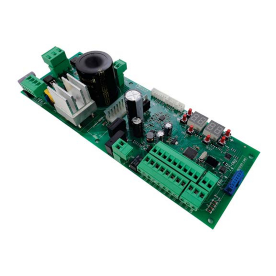
Roger Technology B70/1DCHP Quick Start
Hide thumbs
Also See for B70/1DCHP:
- Instructions and warnings for installation (276 pages) ,
- Instruction and warnings for the installer (236 pages) ,
- Instruction and warnings for the installer (51 pages)
Table of Contents
Advertisement
Quick Links
B70/1DCHP is the range of 36V DC digital controllers installed with the BG30 product series for sliding gate applications.
1. Typical installation
A
A
Power supply
1
Photocell - Receiver
2
Photocell - Transmitter
3
Flashing lamp unit
4
Antenna
5
Selector / Keypad
4
3
1
2
Quick Start B70/1DCHP
H07RN-F 3x1,5 mm
double insulated cable
2
5x0,5 mm
double insulated cable (max. 20 m)
2
3x0,5 mm
double insulated cable (max. 20 m)
2
2x1 mm
double insulated cable (max. 10 m)
2
RG58 50 Ohm cable for external use (max. 10 m)
3x0,5 mm
cable (max. 20 m)
2
Via S. Botticelli 8 • 31021 Bonisiolo di Mogliano Veneto (TV) • ITALIA
P.IVA 01612340263 • Tel. +39 041.5937023 • Fax. +39 041.5937024
info@rogertechnology.com • www.rogertechnology.com
Rev02 03/04/2020
5
1
2
ROGER TECHNOLOGY
EN
Advertisement
Table of Contents

Summary of Contents for Roger Technology B70/1DCHP
- Page 1 Quick Start B70/1DCHP Rev02 03/04/2020 B70/1DCHP is the range of 36V DC digital controllers installed with the BG30 product series for sliding gate applications. 1. Typical installation Power supply H07RN-F 3x1,5 mm double insulated cable Photocell - Receiver 5x0,5 mm double insulated cable (max.
- Page 2 2. Electrical connections F4ES-F4S Series R85/60 BATTERIES FIFTHY/24 1 2 3 2 3 4 5 BG30 2 x 12V 4,5Ah CS/STD BATTERY MOTOR PROG TEST SEC2 SEC1 TRANSFORMER POWER SUPPLY 230Vac Accessories illustrated are indicative only 3. Display: functions and settings PARAMETER PARAMETER VALUE...
- Page 3 4. Before starting ... a) Select the automation system model installed with the parameter . BG30/1600 BG30/1400/R BG30/2200 BG30/1800/HS BG30/1000/HS BG30/1500/HS GATE OPENS TO LEFT GATE OPENS TO RIGHT b) Select the position of the motor relative to the gate with the parameter .
- Page 4 5. Acquisition procedure 1. Press and hold PROG for 4 seconds. 2. APP- appears on the display. 3. Open the release cover. 4. PHAS appears on the display. 5. Wait until the message PHAS flashes. 6. Close the release cover. 7.
- Page 5 9. Photocells grounding connection Grounding connection negative terminal (COM) photocells series F4ES/F4S or other than Roger Technology In case of malfunction, or failure to intervene in case of dimming, or continuous detection, or abnormal behaviour of the automation (gate, overhead door, barrier, etc.), it is advisable to connect the negative terminal (COM) of the photocells to the grounding of the system.


Need help?
Do you have a question about the B70/1DCHP and is the answer not in the manual?
Questions and answers