Roger Technology H70/200AC Instruction And Warnings For The Installer
Hide thumbs
Also See for H70/200AC:
- Instruction and warnings for the installer (172 pages) ,
- Instructions and recomendations for the installer (60 pages) ,
- Quick start manual (7 pages)
Table of Contents
Advertisement
Quick Links
IS43 Rev11 21/02/2020
H70/200AC
centrale di comando per 2 motori asincroni
Istruzioni originali
Istruzioni ed avvertenze per l'installatore
IT
Instructions and warnings for the installer
EN
Anweisungen und Hinweise für den Installateur
DE
Instructions et consignes pour l'installateur
FR
Instrucciones y advertencias para el instalador
ES
Instruções e advertências para o instalador
PT
Aanwijzingen en waarschuwingen voor de installateur
NL
PL
Advertisement
Table of Contents

Related Manuals for Roger Technology H70/200AC


Summary of Contents for Roger Technology H70/200AC
- Page 1 IS43 Rev11 21/02/2020 H70/200AC centrale di comando per 2 motori asincroni Istruzioni originali Istruzioni ed avvertenze per l’installatore Instructions and warnings for the installer Anweisungen und Hinweise für den Installateur Instructions et consignes pour l’installateur Instrucciones y advertencias para el instalador Instruções e advertências para o instalador...
- Page 2 V1.5...
- Page 3 41 40 39 38 37 36 35 34 33 32 31 30 29 28 27 26 25 FUSE F630mA PROG TEST F630mA FCC2 FCC2 FCA2 FCA2 FCC1 FCC1 FCA1 FCA1 H93/RX22A/I ENC2 RICEVITORE RADIO FUSE ENC2 ENC1 F6,3A RADIO RECEIVER ENC1 F6,3A 230Vac...
- Page 4 40 39 38 37 36 35 34 33 32 31 30 29 28 27 26 25 PROG TEST H70/EL 230 Vac Elettroserratura Electric lock 12 Vac 16 VA FUSE T2A...
- Page 5 FOTOCELLULE · PHOTOCELLS COLLEGAMENTO CON 1 COPPIA FOTOCELLULE • CONNECTION WITH 1 PAIR OF PHOTOCELLS 1 2 3 4 5 COS1 COS1 COS2 COS2 USO RACCOMANDATO per fotocellule Serie F2ES - F2S RECOMMENDED USE for Series F2ES - 24V~ F2S photocells COLLEGAMENTO CON 2 COPPIE FOTOCELLULE •...
- Page 6 TEST FOTOCELLULE · PHOTOCELLS TEST ( COLLEGAMENTO CON 1 COPPIA FOTOCELLULE • CONNECTION WITH 1 PAIR OF PHOTOCELLS 1 2 3 4 5 COS1 COS1 COS2 COS2 RACCOMANDATO fotocellule Serie F2ES - F2S RECOMMENDED USE for Series 24V~ F2ES - F2S photocells COLLEGAMENTO CON 2 COPPIE FOTOCELLULE •...
- Page 7 LAMPEGGIANTE · FLASHING LIGHT R92/LED230 230 Vac FIXING LIGHT Lampeggiante Flashing light 230V 40W max Marrone/Brown Blu/Blue Marrone/Brown FUSIBILE / FUSE T500mA Luce di cortesia 230V 100W Courtesy light Marrone/Brown Blu/Blue Marrone/Brown FUSIBILE / FUSE max 1A FIFTHY/230 ENC2 ENC1 230Vac Marrone/Brown Blu/Blue...
- Page 8 con ENCODER OTTICO · with OPTICAL ENCODER ENCODER2 ENCODER1 7 5 0 1 FCC2 Finecorsa chiusura anta 2 FCC2 Closing limit switch leaf 2 FCA2 Finecorsa apertura anta 2 FCA2 Opening limit switch leaf 2 FCC1 Finecorsa chiusura anta 1 FCC1 Closing limit switch leaf 1 FCA1...
- Page 9 The installer is required to measure impact forces and select on the control unit the appropriate speed and torque values to ensure that the door or gate remains ROGER TECHNOLOGY cannot be held responsible for any damage or injury caused by the installation of incompatible components which compromise the safety and correct operation of the device.
- Page 10 Declaration of Conformity The undersigned Dino Florian, legal representative of Roger Technology - Via Botticelli 8, 31021 Mogliano V.to (TV) DECLARES that the H70/200AC digital control unit is compliant with the provisions established by – 2006/95/CE LVD Standard – 2004/108/CE EMC Standard –...
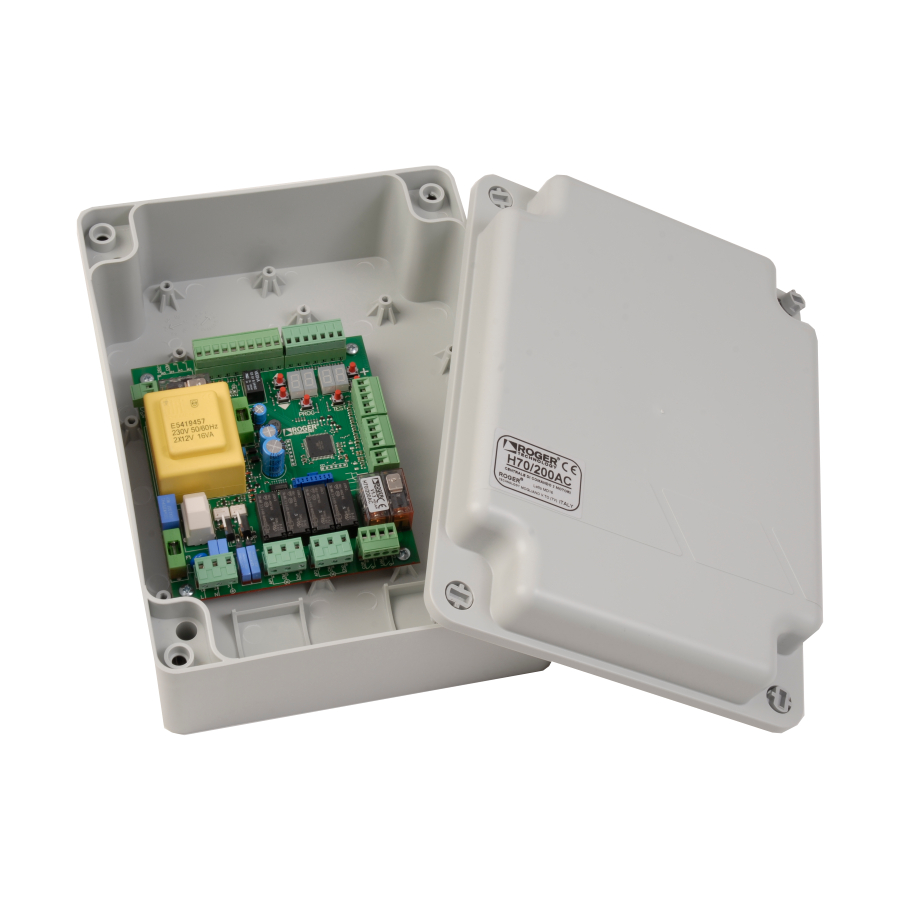
- Page 11 21. Product description The H70/200AC control unit is intended to control gate automation systems with 1 or 2 asynchronous single phase 230 V AC ROGER motors. Use the same type of motor for both gate leaves in automation installations for double leaf swing gates.
- Page 12 Technical characteristics of product H70/200AC MAINS POWER VOLTAGE 230 V ± 10% 50 Hz MAXIMUM MAINS POWER ABSORP- 1400 W TION F1 = F6,3A 250 V (5x20) motor power circuit protection FUSES F2 = F630mA 250 V (5x20) accessories power supply protection...
- Page 13 Description of connections Figures 1-2-3-4 show connection diagrams. Typical installation It is the installer's responsibility to verify the adequacy of the cables in relation to the devices used in the installation and their technical characteristics. Recommended cable H07RN-F 3x1,5 mm double H07RN-F 3x2,5 mm double...
- Page 14 Electrical connections A switch or an omnipolar cut-off switch with a contact opening of at least 3 mm must be installed on the mains power line; put the cut-off switch in OFF position and disconnect any buffer batteries before performing any cleaning or maintenance operations. Ensure that an adequate residual current circuit breaker with a 0.03 A threshold and a suitable overcurrent cut-out are installed upstream the electrical installation in accordance with best practices and in compliance with applicable legislation.
- Page 15 Commands and Accessories If not installed, safety devices with NC contacts must be jumpered at the COM terminals, or disabled by modifying the parameters N.A. (Normally Open). N.C. (Normally Closed). CONTACT DESCRIPTION 10(COR) Output (potential free contact) for connecting courtesy light. 12(LAM) (potential free contact) parameter...
- Page 16 CONTACT DESCRIPTION 30(PED) 31(COM) Partial open control signal input (N.O.). On double leaf gate automation systems, by default, the partial opening command opens LEAF 1 completely. With single leaf swing gate installations, by default, partial opening is 50% of total opening.
- Page 17 Function buttons and display BUTTON DESCRIPTION Next parameter DOWN Previous parameter Increase value of parameter by 1 DOWN Decrease value of parameter by 1 PROG Programme travel PROG TEST TEST Activate TEST mode • Press the UP and/or DOWN buttons to view the parameter you intend to modify. •...
- Page 18 Command and safety device status display mode COMMAND STATUS SAFETY DEVICE STATUS COS1 FCA2 COS2 FCC2 POWER ENC1 ENC2 STOP COMMAND STATUS: The command status indicators on the display are normally OFF. They ILLUMINATE illuminates). SEGMENT COMMAND open step by step mode close partial opening clock...
- Page 19 TEST mode To activate the mode, press the TEST button with the automatic gate system at rest. If the gate is moving, pressing TEST stops the gate. Pressing the button again enables TEST mode. safety device is activated. The command signal status is shown on the left hand side of the display for 5 seconds, ONLY when the respective command signal is active (AP, CH, PP, PE, OR).
- Page 20 Travel acquisition For the system to function correctly, the barrier travel must be acquired by the controller. Before starting: IMPORTANT: Select the automation model installed with parameter A1. It is very important that this parameter is selected correctly. An incorrect setting may cause severe damage or injury.
- Page 21 10.1 Acquisition procedure WITH the encoder enabled, WITH or WITHOUT electric limit switches TEST See chapter 14 and 15 TEST 1 click CLOSED TEST 1 click x2 s PROG PROG PARAM. 25 AP P- DELAY AU to AU to TIME x4 s 1 click ...
- Page 22 10.2 Acquisition procedure WITHOUT encoder, WITH 2 opening and closing limit switches ) WARNING: Before starting the self-acquisition procedure: • set parameters - Deceleration space setting. • set parameter TEST See chapter 14 and 15 TEST 1 click CLOSED TEST 1 click x2 s PROG...
- Page 23 10.3 Acquisition procedure WITHOUT encoder, ONLY for opening limit switch connected to the control unit WARNING: Before starting the self-acquisition procedure: • set parameters - Deceleration space setting. • set parameter TEST See chapter 14 and 15 TEST 1 click CLOSED TEST 1 click...
- Page 24 10.4 Acquisition procedure WITHOUT encoder and WITHOUT electric or magnetic limit switch WARNING: Before starting the self-acquisition procedure: • set parameters - Deceleration space setting. • set parameter TEST See chapter 14 and 15 TEST 1 click CLOSED Sì TEST 1 click x2 s PROG...
- Page 25 Index of parameters FACTORY PARAM. DESCRIPTION PAGE DEFAULT Motor type selection Automatic close after pause time (from gate completely open) Automatic gate closing after mains power outage (black-out) Selecting step mode control function (PP) Condominium function for partial open command (PED) Enabling operator present function.
- Page 26 FACTORY PARAM. DESCRIPTION PAGE DEFAULT Photocell (FT1) mode with gate closed Setting photocell mode during gate opening (FT2) Setting photocell mode during gate closing (FT2) Photocell (FT2) mode with gate closed Enable close command 6 s after activation of photocell (FT1-FT2) Enable braking at open and closed mechanical stop/limit switch Enable braking after activation of photocells Enable braking after STOP command...
- Page 27 Parameter menu PARAMETER PARAMETER VALUE Motor type selection Standard motor (4-pole) - (and all existing codes with the exception of the following codes for the value Slow motor (6-pole) - (R20/302, R20/502, R21/368, H23/282, R41/832, R41/833) Automatic closure after pause time (from gate completely open) Disabled.
- Page 28 Enabling operator present function. Disabled. Enabled. The open (AP) or close (CH) button must be pressed continuously to operate the gate. The gate stops when the button is released. Gate open indicator / photocell test function The indicator is off when the gate is closed, and steadily lit during manoeuvres and when the gate is open. If the gate is stopped in an intermediate position, the lamp extinguishes twice every 15 seconds.
- Page 29 MOTOR 1 operating time increase N.B.: parameter visible only if encoder is disabled Additional time (in seconds) added to the operation time programmed during the acquisition phase. It is NOT necessary to repeat the travel acquisition. MOTOR 2 operating time increase N.B.: parameter visible only if encoder is disabled Additional time (in seconds) added to the operation time programmed during the acquisition phase.
- Page 30 Set initial acceleration when opening/closing (soft-start) Disabled. Enabled. The gate accelerates slowly and progressively at the start of the manoeuvre. Enabled. The gate accelerates even more slowly and progressively at the start of the manoeuvre. different from ). Setting a value of is not recommended for heavy gates.
- Page 31 Setting number of automatic closure attempts after activation of sensing edge or obstacle detection (crush protection) No automatic closure attempts. From 1 to 3 automatic closure attempts. We recommend setting a value equal to or lower than the value set for parameter Automatic closure is only performed if the gate is completely open.
- Page 32 Photocell (FT2) mode with gate closed If the photocell is obstructed, the gate cannot open. The gate opens when an open command is received, even if the photocell is obstructed. The photocell sends the gate open command when obstructed. Enable close command 6 s after activation of photocell (FT1-FT2) N.B.: This parameter is not visible if is set.
- Page 33 COS1 Sensing edge NOT INSTALLED. NC contact (normally closed). The gate reverses only when opening. Contact with 8k2 resistor. The gate reverses only when opening. NC contact (normally closed). The gate always reverses. Contact with 8k2 resistor. The gate always reverses. COS2 Sensing edge NOT INSTALLED.
- Page 34 When the clock function is active, the gate opens and remains open. At the end of the programmed time set with the external device (clock), the gate closes. When the clock function is active, the gate opens and remains open. Any command signal received is ignored.
- Page 35 Password Setting a password prevents unauthorised persons from accessing the settings. With password protection active ( = Only a single password is used to control access to the gate automation system. WARNING: Contact the Technical Support Service if you lose your password. Password activation procedure: •...
- Page 36 Example installation with two opposing automation systems Two opposing sliding gate automation system may be connected to a single H70/200AC control unit. Connect automation system A to terminals AP1-CM-CH1 and connect automation system B to terminals AP2-CM-CH2. H70/EL 230 Vac...
- Page 37 Safety input and command status (TEST mode) PHYSICAL CORRECTIVE DISPLAY POSSIBLE CAUSE ACTION BY SOFTWARE ACTION The safety STOP contact is open. Install a STOP button (NC) or jumper the ST contact with the COM con- tact. Sensing edge COS1 not connected Set the parameter if not used Jumper contact COS1 with contact...
- Page 38 Alarms and faults PROBLEM ALARM POSSIBLE CAUSE ACTION POWER LED off No power. Check power cable. POWER LED off Fuses blown. Replace fuse. Always disconnect from mains power before removing fuses. Example The gate does not open or save. close. Fuse F2 disconnected or damaged.
- Page 39 Initial testing The installer is required to measure impact forces and select on the control unit the appropriate speed and torque values to ensure that the motorised door or gate remains Make sure that the provisions in Chapter 1 "GENERIC WARNINGS are observed. •...
- Page 40 ROGER TECHNOLOGY Via S. Botticelli 8 • 31021 Bonisiolo di Mogliano Veneto (TV) • ITALIA P.IVA 01612340263 • Tel. +39 041.5937023 • Fax. +39 041.5937024 info@rogertechnology.com • www.rogertechnology.com...
Need help?
Do you have a question about the H70/200AC and is the answer not in the manual?
Questions and answers