Table of Contents
Advertisement
FW
P1.00
IS240 Rev.03 30/07/2021
B70/2ML
centrale di comando per cancelli battenti
Istruzioni originali
IT -
Istruzioni ed avvertenze per l'installatore
EN -
Instructions and warnings for the installer
DE -
Anweisungen und Hinweise für den Installateur
FR -
Instructions et consignes pour l'installateur
ES -
Instrucciones y advertencias para el instalador
PT -
Instruções e advertências para o instalado
NL -
Aanwijzingen en waarschuwingen voor de installateur
PL -
Advertisement
Table of Contents

Related Manuals for Roger Technology B70/2ML


Summary of Contents for Roger Technology B70/2ML
- Page 1 P1.00 IS240 Rev.03 30/07/2021 B70/2ML centrale di comando per cancelli battenti Istruzioni originali IT - Istruzioni ed avvertenze per l’installatore EN - Instructions and warnings for the installer DE - Anweisungen und Hinweise für den Installateur FR - Instructions et consignes pour l’installateur...
- Page 3 INDICE • INDEX • INDEX • INDEXER • ÍNDICE • ÍNDICE • INDEX • INDEKS ITALIANO DEUTSCH Avvertenze generali Allgemeine Sicherheitshinweise Dichiarazione di Conformità Konformitätserklärung Simbologia Symbole Descrizione prodotto Produktbeschreibung Caratteristiche tecniche prodotto Technische Daten des Produkts Descrizione dei collegamenti Beschreibung der Anschlüsse Installazione tipo Art der Installation...
- Page 4 ESPAÑOL DUTCH Advertencias generales Algemene waarschuwingen Declaración de Conformidad Verklaring van Overeenstemming Símbolos Symbolen Descripción del producto Beschrijving product Características técnicas del producto Technische kenmerken product Descripción de las conexiones Beschrijving aansluitingen Instalación básica Type installatie Conexiones eléctricas Elektrische aansluitingen Comandos y accesorios Bedieningen en accessoires Teclas de función y pantalla...
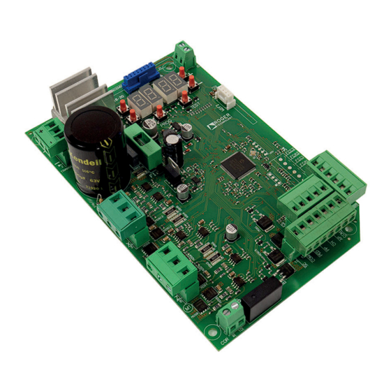
- Page 5 Illustrazioni e schemi - Pictures and schemes - Bilder und Pläne Illustrations et schémas - Ilustraciones y esquemas - Ilustrações e esquemas P1.00 Display a 4 cifre e 6 tasti di programmazione 4 digit display and 6 programming Fusibile F15A buttons Fuse F15A Connettore ad innesto...
- Page 6 H93/RX20/I FUSIBILE RICEVITORE RADIO FUSE RADIO RECEIVER F15A MOTORE 2 MOTOR 2 TRANSFORMER PROG TEST F3.15mA WIFI FUSIBILE FUSE F3.15A ISEL COM PED AP COM MOTORE 1 MOTOR 1...
- Page 7 RG58 max 10 m Antenna ISEL STOP COM PED AP COM (*) Vmedia=12Vdc; Vmax=30Vdc (*) Vaverage=12Vdc; Vmax=30Vdc Utilizzo alternativo dell'uscita COR (par. diverso da 00). Alternative use of COR output (par. different from 00). Luce di cortesia CH IU SO Courtesy light CL O SE D 230 Vac 100W...
- Page 8 COLLEGAMENTO CON 1 COPPIA FOTOCELLULE SINCRONIZZATE (MODALITÁ NORMALE, SOLO COPPIA MASTER) CONNECTION WITH 1 SYNCHRONISED PHOTOCELL PAIR (NORMAL MODE, MASTER PAIR ONLY) ROSSO = libero da jumper RED = jumper free JUMPER DI SINCRONIZZAZIONE ISEL (PER MASTER) SYNCHRONISATION JUMPER 1 2 3 1 2 3 (FOR MASTER) JUMPER DI ALLINEAMENTO...
- Page 9 COLLEGAMENTO CON 2 COPPIE FOTOCELLULE SINCRONIZZATE (MODALITÁ NORMALE, 1 MASTER E 1 SLAVE) CONNECTION WITH 2 SYNCHRONISED PHOTOCELL PAIRS (NORMAL MODE, 1 MASTER AND 1 SLAVE) ROSSO = libero da jumper RED = jumper free JUMPER DI SINCRONIZZAZIONE (PER MASTER) SYNCHRONISATION JUMPER 1 2 3 1 2 3...
- Page 10 TEST FOTOCELLULE · PHOTOCELLS TEST ( COLLEGAMENTO CON 1 COPPIA FOTOCELLULE SINCRONIZZATE (MODALITÁ NORMALE, SOLO COPPIA MASTER) CONNECTION WITH 1 SYNCHRONISED PHOTOCELL PAIR (NORMAL MODE, MASTER PAIR ONLY) ROSSO = libero da jumper RED = jumper free JUMPER DI SINCRONIZZAZIONE (PER MASTER) SYNCHRONISATION JUMPER 1 2 3...
- Page 11 TEST FOTOCELLULE · PHOTOCELLS TEST ( COLLEGAMENTO CON 2 COPPIE FOTOCELLULE SINCRONIZZATE (MODALITÁ NORMALE, 1 MASTER E 1 SLAVE) CONNECTION WITH 2 SYNCHRONISED PHOTOCELL PAIRS (NORMAL MODE, 1 MASTER AND 1 SLAVE) ROSSO = libero da jumper RED = jumper free JUMPER DI SINCRONIZZAZIONE (PER MASTER) SYNCHRONISATION JUMPER...
- Page 12 BATTERY SAVING ( BATTERY SAVING + TEST FOTOCELLULE · PHOTOCELLS TEST ( COLLEGAMENTO CON 1 COPPIA FOTOCELLULE SINCRONIZZATE (MODALITÁ NORMALE, SOLO COPPIA MASTER) CONNECTION WITH 1 SYNCHRONISED PHOTOCELL PAIR (NORMAL MODE, MASTER PAIR ONLY) ROSSO = libero da jumper RED = jumper free JUMPER DI SINCRONIZZAZIONE (PER MASTER) SYNCHRONISATION JUMPER...
- Page 13 BATTERY SAVING ( BATTERY SAVING + TEST FOTOCELLULE · PHOTOCELLS TEST ( COLLEGAMENTO CON 2 COPPIE FOTOCELLULE SINCRONIZZATE (MODALITÁ NORMALE, 1 MASTER E 1 SLAVE) CONNECTION WITH 2 SYNCHRONISED PHOTOCELL PAIRS (NORMAL MODE, 1 MASTER AND 1 SLAVE) ROSSO = libero da jumper RED = jumper free JUMPER DI SINCRONIZZAZIONE (PER MASTER)
- Page 14 INSTALLAZIONE SU SERIE AY (AYRON) • MOTORE 1 (AY250M) AY SERIES (AYRON) INSTALLATION • MOTOR 1 (AY250M) F2 FUSIBILE H93/RX20/I RICEVITORE RADIO FUSE F15A RADIO RECEIVER TRANSFORMER PROG TEST F3.15mA WIFI FUSIBILE FUSE F3.15A FUSIBILE FUSE ISEL COM PED AP COM B71/BC 2 batteries 12 Vdc 1,2 Ah...
- Page 15 COLLEGAMENTI CARICA BATTERIA SU SERIE AY (AYRON) • MOTORE 1 (AY250M) BATTERY CHARGER CONNECTION ON AY (AYRON) SERIES • MOTOR 1 (AY250M) collegamento secondario del trasformatore secondary transformer connection 2 batterie opzionali, installate su motore 2 2 optional batteries, installed on motor 2 12 Vdc 1,2 Ah type AGM...
- Page 16 INSTALLAZIONE BATTERIA SU SERIE AY (AYRON) • MOTORE 2 (AY250S) BATTERY INSTALLATION ON AY (AYRON) SERIES • MOTOR 2 (AY250S) TRANSFORMER PROG TEST F3.15mA WIFI ISEL COM PED AP COM MOTORE 2 MOTORE 1 MOTOR 2 MOTOR 1 T10A 12V 1.2Ah 12V 1.2Ah...
- Page 17 INSTALLAZIONE IN BOX (B70/2ML/BOX) BOX INSTALLATION (B70/2ML/BOX) PRIMARIO TRASFORMATORE MONOFASE POT. 150 VA 50/60 Hz Cod. 702_10/0 FUSIBILE CEI 61558-2-6 FUSE SECONDARIO 230 Vac (B70/2ML/BOX) 115 Vac FUSIBILE FUSE (B70/2ML/BOX/115) FUSE F15A T10A 5x20 TRANSFORMER B71/BC/INT WIFI PROG TEST F3.15mA...
- Page 18 ROGER TECHNOLOGY is not liable for failure to observe the good practices in during use. The safety devices (photocells, sensing edges, emergency stops, etc.) must be in force, the good practices criteria, the installation environment, the operating logic of the system and the forces generated by the motorised door or gate.
- Page 19 The installer is required to measure impact forces and select on the control unit the appropriate speed and torque values to ensure that the door or gate ROGER TECHNOLOGY cannot be held responsible for any damage or injury caused by the installation of incompatible components which compromise the safety and correct operation of the device.
- Page 20 Dispose of and recycle the packaging items according to the provisions of the laws in force. These instructions must be kept and must be made available to any other persons authorised to use the installation. Declaration CE of Conformity DECLARES that the B70/2ML | 20. Place Date Signature...
- Page 21 Symbol for the product disposal according to the WEEE directive, see chapter 20. Product description The 24V B70/2ML control unit controls 1 or 2 ROGER brushless motors in sensorless mode for applications on medium sized gate leaves for residential use. Ensure that the parameter is set correctly.
- Page 22 The total of the absorption values of all the accessories connected must not exceed the maximum power values shown in the table. The values are guaranteed with original ROGER TECHNOLOGY accessories ONLY. All the connections are protected by fuses (refer to the table). The courtesy light requires an external fuse.
- Page 23 Description of connections Typical installation It is the installer's responsibility to verify the adequacy of the cables in relation to the devices used in the installation and their technical characteristics. Recommended cable Power supply double insulated cable Motor 1 Cable 3x2,5 mm² (max 10 3x4 mm²...
- Page 24 Electrical connections buffer batteries before performing any cleaning or maintenance operations. Ensure that an adequate residual current circuit breaker with a 0.03 A threshold and a suitable practices and in compliance with applicable legislation. located inside the control panel box. Strip the insulation from the ends of the power cable wires which will be connected to the Measure the voltage on the primary mains power connection with a tester.
- Page 25 Commands and Accessories If not installed, safety devices with NC contacts must be jumpered at the COM terminals, or disabled by modifying the parameters N.A. (Normally Open) . N.C. (Normally Closed). CONTACT DESCRIPTION 9 (COR) Output (potential free contact) for connecting courtesy light. 9 (COR) •...
- Page 26 CONTACT DESCRIPTION 16(AP) 17(COM) Open control signal input (N.O.). IMPORTANT: persistent activation of the opening command prevents automatic reclosure; the auto matic reclosure time count is resumed when the opening command is released. 15(CH) 17(COM) Close command input (N.O.). 14(PP) 17(COM) Step by step mode command input (N.O.).
- Page 27 Function buttons and display BUTTON DESCRIPTION Next parameter DOWN Previous parameter Increase value of parameter by 1 DOWN Decrease value of parameter by 1 PROG Programme travel PROG TEST TEST Activate TEST mode • Press the UP buttons to view the parameter you intend to modify. •...
- Page 28 Command and safety device status display mode COMMAND STATUS SAFETY DEVICE STATUS COMMAND STATUS: The command status indicators on the display (segments AP = open, PP = step mode, CH = close, PED = partial opening, ORO= clock) are normally off.
- Page 29 Travel acquisition For the system to function correctly, the gate travel must be acquired by the control. 10.1 Before starting 1. Select the automation system model installed with the parameter KEY: HIGH SPEED Motor MOTOR SELECTION MODEL CONFIGURATIONS TYPE AYRON SERIES NOTE: for gate leaves up to 2.5 m BE20/200 NOTE: for gate leaves up to 3 m...
- Page 30 TEST SEE CHAPTER 14 e 15 1 click Until... TEST PROG ACQUISITION TEST PROCEDURE AP P- CHAP. 11.2 1 click CLOSE Press and hold on TEST ACQUISITION PROCEDURE CHAP. 11.2 1 click 10.2 Acquisition procedure: PROG PROG AP P- AU to x4 s 1 click MOTOR 1...
-
Page 31: Table Of Contents
Index of parameters FACTORY PARAM. DESCRIPTION PAGE DEFAULT Selecting automation system model CHAP. 10 Automatic closure after pause time (from gate completely open) Selecting step mode control function (PP) Condominium function for partial open command (PED) Enabling operator present function MOTOR 1 Setting deceleration during opening and closing MOTOR 2 Setting deceleration during opening and closing Adjusting LEAF 1 position control... -
Page 32: Factory Default
FACTORY PARAM. DESCRIPTION PAGE DEFAULT Number of automatic closure attempts after activation of sensing edge or obstacle detection (crush protection) Setting photocell mode during gate opening (FT1) Setting photocell mode during gate closing (FT1) Photocell (FT1) mode with gate closed Setting photocell mode during gate opening (FT2) Setting photocell mode during gate closing (FT2) Photocell (FT2) mode with gate closed... - Page 33 FACTORY PARAM. DESCRIPTION PAGE DEFAULT View manoeuvre hour counter View control unit days on counter Password Password change protection...
-
Page 34: Selecting Automation System Model
Parameters menu PARAMETER PARAMETER VALUE Selecting automation system model WARNING! If this parameter is not set correctly, the automation system may not function properly. N.B.: in the event of a reset to restore the default parameters, this parameter must be set again manually. AYRON SERIES - IRREVERSIBLE HIGH-SPEED gear motor with articulated arm BE20/200 - IRREVERSIBLE arm piston with worm screw MONOS4 - IRREVERSIBLE telescopic arm piston... -
Page 35: Adjusting Leaf 1 Position Control
Gate open indicator / photocell test function and “battery saving” The indicator is off when the gate is closed, and steadily lit during manoeuvres and when the gate is open. If the gate is stopped in an intermediate position, the lamp extinguishes twice every 15 seconds. Set to When the gate is completely open or closed, the control unit deactivates any accessories connected to terminal SC to reduce battery consumption. -
Page 36: Setting Automatic Closing Time
Setting automatic closing time The timer starts from the gate open state and continues for the set time. Once the set time is reached, the gate closes automatically. The timer count restarts if a photocell is triggered. IMPORTANT: persistent activation of the opening command prevents automatic reclosure; the automatic reclosure time count is resumed when the opening command is released. -
Page 37: Setting Obstacle Impact Force Sensitivity Motor 1
Setting obstacle impact force sensitivity MOTOR 1 If the reaction time to obstacle impact force is too long, reduce the value of the parameter. If the impact force exerted on obstacles is too high, reduce the value of parameter N.B: repeat the acquisition procedure after any change made to this parameter. = minimum obstacle impact force ... -
Page 38: Setting Photocell Mode During Gate Closing (Ft1)
TEMPORARY STOP. The gate stops as long as the photocell is obstructed. The gate resumed opening when the photocell is cleared. DELAYED REVERSE. The gate stops if the photocell is obstructed. The gate closes when the photocell is cleared. Setting photocell mode during gate closing (FT1) DISABLED. -
Page 39: Selecting The Type Of Photocell Test On Input Ft1
N.C. N.C. Selecting the type of photocell test on input FT1 This parameter is visible if is set. If the photocell test is enabled, the control unit will check the photocells connected to input FT1 are working properly. Selecting the type of photocell test on input FT2 This parameter is visible if is set. - Page 40 • seconds by pressing CHB on the remote control. Press CHB to activate partial opening. Selecting courtesy light mode NOTE: The parameter is not visible if par. is other than Disabled. ACTIVE. The light remains lit for the entire duration of the manoeuvre. From 3 to 90 s.
- Page 41 Battery consumption selection normal. Selection of the battery operation management Setting a value different than a battery voltage level check is activated. The desired operation type can be selected via parameter and an error alert can be activated through the COR output via parameter The control unit always accepts commands until the battery is completely exhausted.
- Page 42 View control unit days on counter The number consists of the values of the parameters from N.B.: The values shown in the table are indicative only. Days with unit switched on. = 123 days. Password Setting a password prevents unauthorised persons from accessing the settings. With password protection active ( Only a single password is used to control access to the gate automation system.
- Page 43 Safety input and command status (TEST mode) DISPLAY POSSIBLE CAUSE ACTION BY SOFTWARE PHYSICAL CORRECTIVE ACTION The safety STOP contact is open. Check that parameter is set cor Install a STOP button (NC) or jumper the Incorrect setting of parameter rectly ST contact with the COM contact.
- Page 44 Alarms and faults PROBLEM ALARM POSSIBLE CAUSE ACTION POWER LED off No mains power. Check the mains power cable. POWER LED off Fuses blown. Replace fuse. Always disconnect from mains Check fuses F1, F2 and F3. power before removing fuses. Input mains power voltage fault.
- Page 45 THE INFO MODE x5 s INFO mode may be used to view certain parameters measured by the B70/2ML controller. Press and hold the TEST button for 5 seconds from the “View command signals and safety devices” mode with the motor stationary. The control unit displays the following parameters and the corresponding measured values in...
- Page 46 Example: 1-PRESS 2-RELEASE 3-RE-PRESS OPEN CLOSE OPEN CLOSE APRE CLOSE within 1 s • THE MOTOR in question is activated on opening by pressing the "UP ARROW" key, or on closure by pressing the "DOWN ARROW" key. • the button, release within 1 second and then press and hold. The motor stops as soon as the button is released. WARNING: during the check, the motor revolution count (position) is updated but the gate leaf alignment control function may cause problems.
- Page 47 POSITION RECOVERY WITH CONTROL UNIT NOT POWERED (BLACK OUT) AND INTERMEDIATE POSITION OF LEAVES (NOT COMPLETELY CLOSED OR NOT COMPLETELY OPEN) and a blackout occurs, when the mains voltage returns, in whatever position the leaves are, At the next command, the gate leaves perform the opening manoeuvre at low speed to restore normal operating mode. is at , upon receipt of a command, the repositioning procedure begins, which will be completed when the leaves have performed a complete run without...
- Page 48 ROGER TECHNOLOGY is the exclusive proprietor holder of all rights regarding this publication. or any alterations to this document are prohibited without express prior authorised from by ROGER TECHNOLOGY. ROGER TECHNOLOGY reserves the right to modifying or perfecting the product, which will not imply a FW version change.
- Page 51 ROGER TECHNOLOGY...
Need help?
Do you have a question about the B70/2ML and is the answer not in the manual?
Questions and answers