Roger Technology B70/1DCHP Instruction And Warnings For The Installer
Hide thumbs
Also See for B70/1DCHP:
- Instructions and warnings for installation (276 pages) ,
- Instruction and warnings for the installer (236 pages) ,
- Quick start (5 pages)
Table of Contents
Advertisement
Quick Links
FW
P2.00
IS142 Rev.12 20/12/2022
B70/1DCHP
centrale di comando 36Vdc per cancelli scorrevoli
Istruzioni originali
IT -
Istruzioni ed avvertenze per l'installatore
EN -
Instructions and warnings for the installer
DE -
Anweisungen und Hinweise für den Installateur
FR -
Instructions et consignes pour l'installateur
ES -
Instrucciones y advertencias para el instalador
PT -
Instruções e advertências para o instalado
NL -
Aanwijzingen en waarschuwingen voor de installateur
PL -
Advertisement
Table of Contents

Related Manuals for Roger Technology B70/1DCHP


Summary of Contents for Roger Technology B70/1DCHP
- Page 1 P2.00 IS142 Rev.12 20/12/2022 B70/1DCHP centrale di comando 36Vdc per cancelli scorrevoli Istruzioni originali IT - Istruzioni ed avvertenze per l’installatore EN - Instructions and warnings for the installer DE - Anweisungen und Hinweise für den Installateur FR - Instructions et consignes pour l’installateur...
- Page 2 INDICE • INDEX • INDEX • INDEXER • ÍNDICE • ÍNDICE • INDEX • INDEKS ITALIANO DEUTSCH Avvertenze generali Allgemeine Sicherheitshinweise Simbologia Symbole Descrizione prodotto Produktbeschreibung Aggiornamenti versione P2.00 Aktualisierungen Version P2.00 Technische Daten des Produkts Caratteristiche tecniche prodotto Descrizione dei collegamenti Beschreibung der Anschlüsse Installazione tipo Art der Installation...
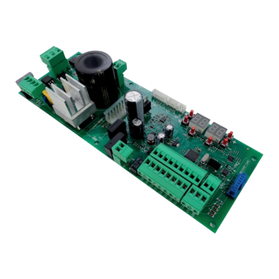
- Page 3 P2.00 Connettori di collegamento encoder, Plug for encoder, limit switch and unlock microswitch connection Connettore scheda carica Display a 4 cifre e 6 tasti di Collegamento batterie batterie programmazione Batteries connection Plug for battery charger 4 digit display and 6 programming buttons Microcontrollore Collegamento...
-
Page 5: Radio Receiver
FUSIBILE FUSE FUSIBILE FUSE FUSIBILE FUSE Alimentazione Power supply BATTERY CHARGER +LAM +24V COS2 COS1 H93/RX22A/I RICEVITORE RADIO RADIO RECEIVER... - Page 6 Luce di cortesia Courtesy light 230Vac 100W marrone brown blue marrone brown FUSIBILE FUSE max 1A +LAM Spia cancello aperto Lampeggiante Open gate light Flashing light 24Vdc 3W 24Vdc max 25W +24V Apertura parziale Partial opening COS2 Passo passo Bordo sensibile 2 Step by step Safety edge 2 COS1...
- Page 7 COLLEGAMENTO CON 1 COPPIA FOTOCELLULE SINCRONIZZATE (MODALITÁ NORMALE, SOLO COPPIA MASTER) CONNECTION WITH 1 SYNCHRONISED PHOTOCELL PAIR (NORMAL MODE, MASTER PAIR ONLY) ROSSO = libero da jumper RED = jumper free JUMPER DI SINCRONIZZAZIONE (PER MASTER) SYNCHRONISATION JUMPER (FOR MASTER) 1 2 3 1 2 3 JUMPER DI ALLINEAMENTO...
- Page 8 COLLEGAMENTO CON 2 COPPIE FOTOCELLULE SINCRONIZZATE (MODALITÁ NORMALE, 1 MASTER E 1 SLAVE) CONNECTION WITH 2 SYNCHRONISED PHOTOCELL PAIRS (NORMAL MODE, 1 MASTER AND 1 SLAVE) ROSSO = libero da jumper RED = jumper free JUMPER DI SINCRONIZZAZIONE (PER MASTER) SYNCHRONISATION JUMPER 1 2 3 1 2 3...
- Page 9 TEST FOTOCELLULE · PHOTOCELLS TEST ( COLLEGAMENTO CON 1 COPPIA FOTOCELLULE SINCRONIZZATE (MODALITÁ NORMALE, SOLO COPPIA MASTER) CONNECTION WITH 1 SYNCHRONISED PHOTOCELL PAIR (NORMAL MODE, MASTER PAIR ONLY) ROSSO = libero da jumper RED = jumper free JUMPER DI SINCRONIZZAZIONE (PER MASTER) SYNCHRONISATION JUMPER (FOR MASTER)
- Page 10 TEST FOTOCELLULE · PHOTOCELLS TEST ( COLLEGAMENTO CON 2 COPPIE FOTOCELLULE SINCRONIZZATE (MODALITÁ NORMALE, 1 MASTER E 1 SLAVE) CONNECTION WITH 2 SYNCHRONISED PHOTOCELL PAIRS (NORMAL MODE, 1 MASTER AND 1 SLAVE) ROSSO = libero da jumper RED = jumper free JUMPER DI SINCRONIZZAZIONE (PER MASTER) SYNCHRONISATION JUMPER...
- Page 11 BATTERY SAVING ( BATTERY SAVING + TEST FOTOCELLULE · PHOTOCELLS TEST ( COLLEGAMENTO CON 1 COPPIA FOTOCELLULE SINCRONIZZATE (MODALITÁ NORMALE, SOLO COPPIA MASTER) CONNECTION WITH 1 SYNCHRONISED PHOTOCELL PAIR (NORMAL MODE, MASTER PAIR ONLY) ROSSO = libero da jumper RED = jumper free JUMPER DI SINCRONIZZAZIONE (PER MASTER) SYNCHRONISATION JUMPER...
- Page 12 BATTERY SAVING ( BATTERY SAVING + TEST FOTOCELLULE · PHOTOCELLS TEST ( COLLEGAMENTO CON 2 COPPIE FOTOCELLULE SINCRONIZZATE (MODALITÁ NORMALE, 1 MASTER E 1 SLAVE) CONNECTION WITH 2 SYNCHRONISED PHOTOCELL PAIRS (NORMAL MODE, 1 MASTER AND 1 SLAVE) ROSSO = libero da jumper RED = jumper free JUMPER DI SINCRONIZZAZIONE (PER MASTER)
- Page 13 PR1 PR2...
- Page 14 Nero/Black (26 Vac) Blu/Blue (19 Vac)
- Page 15 BG30 High Speed Cavo motore Motor cable B72/BRAKE2...
-
Page 16: Magnetic Limit Switch
FINECORSA MECCANICO MECHANICAL LIMIT SWITCH FINECORSA MAGNETICO MAGNETIC LIMIT SWITCH... - Page 17 BATTERY B71/BCHP BATTERY CHARGER BATTERY FC SB PROG TEST 10 11 12 13 14 15 16 17 18 SEC2 SEC1 TRANSFORMER BLACK FUSE T10A 5x20 2 x 12V 4,5Ah AGM Battery ONLY...
-
Page 18: General Safety Precautions
ROGER TECHNOLOGY is not liable for failure to observe the good practices in during use. The safety devices (photocells, sensing edges, emergency stops, etc.) must be... - Page 19 The installer is required to measure impact forces and select on the control unit the appropriate speed and torque values to ensure that the door or gate ROGER TECHNOLOGY cannot be held responsible for any damage or injury caused by the installation of incompatible components which compromise the safety and correct operation of the device.
- Page 20 Only use original spare parts when repairing or replacing products. The installer must provide the user with complete instruction for using the motorised door or gate in automatic, manual and emergency modes, and must hand the operating instructions to the user of the installation upon completion. Keep away from hinges and moving parts.
-
Page 21: Product Description
22. Product description The B70/1DCHP 36 V digital control unit uses a high resolution encoder for the sensored power control of ROGER sliding gate leaf automation systems. Ensure that the parameter A1 is set correctly. If this parameter is not set correctly, the automation system may not function properly. - Page 22 The total of the absorption values of all the accessories connected must not exceed the maximum power values shown in the table. The values are guaranteed with original ROGER TECHNOLOGY accessories ONLY. The use of non-original accessories may lead to malfunctioning. ROGER TECHNOLOGY declines all responsibility for incorrect or non-conforming installations.
-
Page 23: Description Of Connections
Description of connections To access the control connection terminal board, remove the motor cover as shown in Figure 2-3-4-5 shows connection diagrams for connecting mains voltage to the motor control unit Typical installation It is the installer's responsibility to verify the adequacy of the cables in relation to the devices used in the installation and their technical characteristics. -
Page 24: Electrical Connections
Measure the voltage on the primary mains power connection with a tester. TRANSFORMER For the Brushless automation system to function correctly, the mains power voltage must be: - 230Vac ±10% for the B70/1DCHP control unit. 220÷230 - 115Vac ±10% for the B70/1DCHP/115 control unit. -COM... - Page 25 16(COM) STOP command input (NC). The current manoeuvre is arrested if the safety contact opens. N.B.: the controller is supplied with this contact already jumpered by ROGER TECHNOLOGY. 21(ANT) Antenna connector for slot-in radio receiver board. Use RG58 if an external antenna is used; maximum recommended length: 10 m.
-
Page 26: Receiver Card
Connector for connecting to encoder installed on motor. WARNING! Always disconnect from electrical power before disconnecting or connecting the encoder cable. N.B.: Ready wired in factory by ROGER TECHNOLOGY. Connector (N.C. contacts) for connecting mechanical limit switch (see - detail B) or mag- netic limit switch (see - detail C). -
Page 27: Function Buttons And Display
Function buttons and display BUTTON DESCRIPTION Next parameter DOWN Previous parameter DOWN Increase value of parameter by 1 Decrease value of parameter by 1 PROG Travel acquisition PROG TEST TEST Activate TEST mode • Press the UP and/or DOWN buttons to view the parameter you intend to modify. •... -
Page 28: Command Status
10.2 Command and safety device status display mode COMMAND STATUS SAFETY DEVICE STATUS COS1 COS2 POWER STOP COMMAND STATUS: The command status indicators on the display are normally OFF. They ILLUMINATE when a command is received (e.g.: when a step mode command is received, the segment PP illuminates). - Page 29 10.3 TEST mode To activate the mode, press the TEST button with the automatic door system at rest. If the gate is moving, pressing TEST stops the gate. Pressing the button again enables TEST mode. device is activated. The command signal status is shown on the left hand side of the display for 5 seconds, ONLY when the respective command signal is active (AP, CH, PP, PE, OR).
-
Page 30: Before Starting
Travel acquisition For the system to function correctly, the gate travel must be acquired by the control. 11.1 Before starting 1. Select the automation system model installed with the parameter KEY: HIGH SPEED Motor REVERSIBLE Motor MOTOR SELECTION MODEL CONFIGURATIONS TYPE BG30/1600 up to 1600 kg... - Page 31 TEST SEE CHAPTER 16 and 17 1 click Until ... TEST PROG ACQUISITION TEST AP P- PROCEDURE CHAP. 11.2 1 click CLOSE 1 click Press and hold on TEST ACQUISITION PROCEDURE CHAP. 11.2 1 click 11.2 Acquisition procedure: PROG FO TO AP P- PH A5 PH A5...
-
Page 32: Parameter's Index
Parameter's index FACTORY PARAM. DESCRIPTION PAGE VALUE Selecting automation system model see chap. 13 Automatic closure after pause time (from gate completely open) Automatic gate closing after mains power outage Selecting step mode control function (PP) Condominium function for partial open command (PED) Enabling operator present function Gate open indicator / photocell test function and “battery saving”... - Page 33 FACTORY PARAM. DESCRIPTION PAGE VALUE Photocell (FT2) mode with gate closed Enable close command 6 s after activation of photocell (FT1-FT2) Setting motor stop distance Selecting installation position of motor relative to gate (seen from interior side) Selecting courtesy light mode Enable safeguarded gate closure/opening Setting safeguarded closure/opening activation time Selection of the battery operation management...
-
Page 34: Parameter Menu
Parameter menu PARAMETER PARAMETER VALUE Selecting automation system model WARNING! If this parameter is not set correctly, the automation system may not function properly. N.B.: in the event of a reset to restore the default parameters, this parameter must be set again manually. BG30/1600 - IRREVERSIBLE motor for gate leaves up to 1600 Kg. - Page 35 Condominium function for partial open command (PED) Disabled. The gate opens partially in step mode: open-stop-close-stop-open... Enabled. Partial commands are ignored during gate opening. Enabling operator present function Disabled. Enabled. The open (AP) or close (CH) button must be pressed continuously to operate the gate. The gate stops when the button is released.
- Page 36 Enabling of management for opening with automatic re-closure exclusion If enabled, the exclusion of automatic re-closure only applies for the command selected via the parameter. For example: if you set , automatic re-closure is excluded following an AP command, but it is activated following a PP or PED command.
- Page 37 Setting motor torque during position recovery Adjust motor torque with parameter if, during position recovery, the values set with parameters are insuf- If position recovery is not completed, normal gate operation will not be resumed. The response of the obstacle detection system depends solely on the values set for parameters The response of the obstacle detection system depends on the values set for parameters and on the maxi- mum current value stored during travel acquisition.
- Page 38 Setting photocell mode during gate opening (FT2) DISABLED. Photocell is not active or not installed. STOP. The gate stops and remains stationary until the next command is received. IMMEDIATE REVERSE. The gate reverses immediately if the photocell is activated during gate opening. TEMPORARY STOP.
- Page 39 N.B.: With ROGER TECHNOLOGY plug-in radio receiver board. N.B.: With ROGER TECHNOLOGY plug-in radio receiver board. STEP MODE. PARTIAL OPENING OPENING CLOSING. STOP. Courtesy light. The output COR is managed from the remote control. The light remains lit as long as the remote control is active.
- Page 40 Setting safeguarded closure/opening activation time N.B.: this parameter is not visible if the value of parameter Wait time settable from 2 to 90 s. Wait time settable from 2 to 9 min. Selection of the battery operation management Setting a value different than a battery voltage level check is activated.
- Page 41 View manoeuvre counter The number consists of the values of the parameters from multiplied by 100. N.B.: The values shown in the table are indicative only. Manoeuvres performed. Example: x100 = 1.234.500 manoeuvres. View manoeuvre hour counter The number consists of the values of the parameters from N.B.: The values shown in the table are indicative only.
- Page 42 Special parameters for HIGH SPEED series The BG30/HS series (High Speed) is a family of digital brushless high speed sliding motor units for sliding gates weighing up to 1000 kg, 1500 kg or 1800 kg and dedicated exclusively to residential applications. High Speed technology makes it possible for the automation system to operate 100% faster than a conventional system, and allows independent management of speed, acceleration, deceleration and the safety devices used in the system.
- Page 43 Special parameters for BG30/1400/R series The BG30/R series (REVERSIBLE) is a family of digital brushless motor units for sliding gates weighing up to 1400 kg and dedicated exclusively to residential and industrial applications. REVERSIBLE technology makes it possible to open and close the gate without releasing the motor even in the event of power failure.
- Page 44 Safety input and command status (TEST mode) With no currently active commands, press the TEST button and check the following: DISPLAY POSSIBLE CAUSE ACTION BY SOFTWARE PHYSICAL CORRECTIVE ACTION The release handle is open. Close the release handle and turn the key to the close position.
-
Page 45: Alarms And Faults
Alarms and faults PROBLEM ALARM POSSIBLE CAUSE ACTION LED POWER off No power. Check power cable. LED POWER off Fuses blown. Replace fuses. Always disconnect from mains power before removing fuses. Input mains power voltage fault. Disconnect from mains power, wait 10 seconds then reconnect to the mains and switch on. - Page 46 PROBLEM ALARM POSSIBLE CAUSE ACTION Encoder malfunction. Press TEST button. Replace the encoder if the pro- blem persists. (EnE5) If the unit contains dirt, moisture, insects or other foreign matter, disconnect from mains power and clean the board and the encoder. Replace the enco- der if the problem persists.
- Page 47 INFO MODE x5 s INFO mode may be used to view certain parameters measured by the B70/1DCHP controller. Press and hold the TEST button for 5 seconds from the “View command signals and safety devices” mode with the motor stationary.
-
Page 48: Mechanical Release
Mechanical release In the event of a fault or mains power loss, the gate may be released and opened manually. For further information, refer to the locking/release operation in the manual of the automation system. If the gate releases with the controller unit powered, the message When the release system is restored to the normal operating position, if the gate is not completely open or completely closed the next time a command is received, the control initiates a position recovery procedure (see chapter 20). -
Page 49: Maintenance
Declaration CE of Conformity The undersigned Dino Florian, legal representative of Roger Technology - Via Botticelli 8, 31021 Mogliano V.to (TV) DECLARES that the B70/1DCHP digital control unit is compliant with the provisions established by Community directives: – 2014/35/EU LVD Standard –... - Page 50 ROGER TECHNOLOGY Via S. Botticelli 8 • 31021 Bonisiolo di Mogliano Veneto (TV) • ITALIA P.IVA 01612340263 • Tel. +39 041.5937023 • Fax. +39 041.5937024 info@rogertechnology.com • www.rogertechnology.com...
Need help?
Do you have a question about the B70/1DCHP and is the answer not in the manual?
Questions and answers