
Related Manuals for Axminster AP3352B


Summary of Contents for Axminster AP3352B
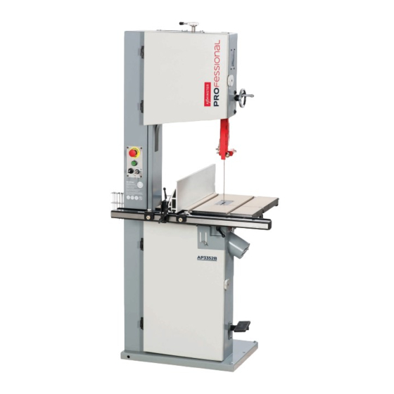
- Page 1 Code 107644 Original Instructions AP3352B Woodworking Bandsaw AT: 08/02/2022 BOOK VERSION: 6...
-
Page 2: Eu Declaration Of Conformity
Exploded Diagrams/Lists 22-23-24-25-26-27-28-29-30-31-32-33 Wiring Diagram Notes EU DECLARATION OF CONFORMITY Cert No: HW615E EU Declaration of Conformity Axminster Tool Centre Ltd This machine complies with the following directives: Axminster Devon EX13 5PH UK axminstertools.com 2006/42/EC EN 1807-1: 2013 EN 60204-1:2018... -
Page 3: What's Included
WHAT’S INCLUDED Quantity Item Part Model Number AP3352B Bandsaw Instruction Manual Tool Storage Bracket Dust Extraction Cover Floor Mounting Feet 12x60 Flat Washers Spring Washers Cap Screw 5x12 Hex Key 5mm Hex Key 4mm Hex Key 3mm Hex Key 2mm Gas Strut with x2 Pins &... -
Page 4: General Instructions For 230V Machines
• Leave machine unplugged until work is about to commence. around you and USE YOUR COMMON SENSE. • Always disconnect by pulling on the plug body and not the cable. SPECIFICATION Code 107644 Model AP3352B Rating Professional Power 2.2kW 230V 1ph Plug 3 pin 16 Amp Blade Speed... - Page 5 ASSEMBLY Floor Mounting Feet Table Support Gas Strut Remove the shipping pallet and place aside. Locate the four mounting feet (E) and with help mount them to each corner of the bandsaws base, see fig 01. Manoeuvre the bandsaw to the required position with plenty of space around the unit.
- Page 6 ASSEMBLY Rip-Fence Assembly Follow the instructions below to assemble the fence. Front fence rail Split pin Countersunk Hex screw Fence scale block cap head screws Gas strut Rear fence guide rail 3. Table gas strut installed. Hex screws...
- Page 7 ASSEMBLY Tilt Quadrant Slack Pin Bolts Lower the tabe down and nip-up the two clamping handles to secure it in place. Using a Hex key, screw in the two caphead pin bolts into the tilt quadrant mechanisum Fence clamp assembly until there is no side play movement in the table, see the images below.
-
Page 8: Illustration & Parts Description
ILLUSTRATION & PARTS DESCRIPTION Upper Wheel Door NVR Switch with isolating Key Lock Tool Storage Bracket Main Frame Lower Wheel Door Manual motor brake lever Blade Tensioning Lever Blade Tracking Window Upper Blade Guide adjusting Wheel Saw Table Dust Extraction Outlet Upper Door Lock Knob Upper Blade Guide Rip Fence Assembly... - Page 9 ILLUSTRATION & PARTS DESCRIPTION Dust extraction outlet Emergency stop (A), ‘ON’ button (B), Selector switch (C), Power isolating key lock (D) Fence scale (E) and pointer (F) To disengage the electric motor brake Table clamping handle (G), Table tilt scale (H), manually, pull the lever back towards you Scale pointer (I), Table tilt operating wheel (J)
- Page 10 ILLUSTRATION & PARTS DESCRIPTION Release Blade tensioning lever (K) Tension Tracking knob & locking wheel (L) Quick release tensioning lever (M), Upper guide adjusting wheel (N) Upper guide locking handle (O) Blade tension scale (P) Four fence alignment Hex screws (Q) adjust each Hex screw until Corner peddle foot brake stop the fence is perpendicular with the blade and the table Press down to stop the bandsaw instantly...
- Page 11 ILLUSTRATION & PARTS DESCRIPTION Upper Guide Assembly Lower Guide Assembly Blade Guide Description Guide Holder Guide Holder Cap head screw Guide Bearing Adjusting knob Guide Bearings Guide Bearing Clamping knob Thrust Bearing Thrust Bearing Clamping Knob Guide Assembly Cap head Screws Guide Assembly...
- Page 12 SETUP/ADJUSTMENT Fig 04-05 MOVE THE LOCK SWITCH (D) TO THE POWER ON POSITION, MOVE THE OTHER SWITCH TO THE ‘BRAKE OFF’ POSITION & PRESS THE GREEN BUTTON, SEE PAGE 9. Tensioning and Tracking the Blade Make sure both top and bottom blade guides are clear of the blade Open the upper and lower wheel doors, giving good access to the saw wheels.
- Page 13 SETUP/ADJUSTMENT Fig 07 Power on Clamping handle Close the upper/lower doors, move the selector switch to the Fig 09 ‘RUN’ position and turn the ‘LOCK’ key to the power on position see fig 07. Stand clear and start the saw by pressing the ‘GREEN’ button.
- Page 14 SETUP/ADJUSTMENT Fig 11 MOVE THE SELECTOR SWITCH TO ‘BRAKE OFF’ POSITION Upper Blade Guides Open the blade guide access door (1). Loosen the locking knobs (2), adjust the fore and aft position of the guide bearings so they are approximately 2mm behind the gullets of the saw blade, see fig 15-16-17.
- Page 15 SETUP/ADJUSTMENT Fig 22-23 Fig 18-19-20-21 0.5mm Loosen the clamping knobs ( 2) and adjust the guide bearings so they are approximately 0.5mm to the blade, see fig 22-23. NOTE: A sheet of A4 of photocopy paper is approximately 0.5mm thick. Re-tighten knobs (2). Close the blade guide access door (1).
- Page 16 SETUP/ADJUSTMENT Fig 26-27-28-29 0.5mm Adjusting knobs Guard clamp Thrust bearing Remove the lower blade guard (6). Loosen the clamping knob Adjust the guide bearings with a clearance of 0.5mm between (7) and adjust the lower guide bearings (8), so they are 2mm the blade and nip-up the clamping knobs (7).
- Page 17 SETUP/ADJUSTMENT Tilt Quadrant Slack Pin Bolts Lower the table down and lock in place. There are two caphead pins bolt, forward and aft on the tilt quadrant mechanism. Adjust each bolt clockwise to take up the slack this will remove any side play movement from the table, see image below.
-
Page 18: Changing The Saw Blade
CHANGING THE SAW BLADE Upper door lock Lower door lock MOVE THE SELECTOR SWITCH TO ‘BRAKE OFF’ POSITION... - Page 19 CHANGING THE SAW BLADE Fig 31 Fig 34-35 Set the upper blade guide assembly approximately midway in the throat. Open the top and bottom covering doors and remove the table insert (B), see fig 31. Table slot Remove the table stabilising bolt (C) and release the blade tension by pushing the quick release lever up, see fig 32.
-
Page 20: Maintenance
CHANGING THE SAW BLADE Turn the top wheel by hand to ensure the blade will not skip off the wheels and the blade is travelling in the blade guides. Re-fit the table stabilising bolt and table insert. Loosen the upper guide clamp (2) and position the assembly (3) so that the top of the blade guide is level with the centre of the top drive wheel, see fig 36-37. - Page 21 MAINTENANCE Clean out impacted ‘crud’ and saw dust Clean out impacted ‘crud’ and saw dust...
- Page 22 EXPLODED DIAGRAMS/LISTS Frame Assembly Exploded View...
- Page 23 EXPLODED DIAGRAMS/LISTS Name Description Dust Guard HW616-01-76 Hex Socket Cap Screw GB/T70.1 M6 X 12 Flat Washer GB/T97.1 6 Hinge HW616-01-73 Spring Washer GB/T 93 6 Door HW615-01-90 Cap Screw GB/T70.2 M6 X 16 Shockproof Soft Article 1.9 m Lock Nut GB/T 6170 M12 Position Indicator HW615-04-05...
- Page 24 EXPLODED DIAGRAMS/LISTS Wheels and Blade Tension Level Assembly...
- Page 25 EXPLODED DIAGRAMS/LISTS Name Description Spring Bracket HW616-04-03B Knob HW615-04-40 Shaft HW616-04-02 Handle HW615-04-08 Lock Nut GB/T889.1 M10 Adjusting Nut HW616-04-23 Lock Nut GB/T6172.1 M12 Knob M8X35 Square Screw HW616-04-16B Flat Washer GB/T97.1 12 Rubber Belt HW615-02-06 Spring Washer GB/T93 12 Square Shaft HW616-04-20C Lock Nut...
- Page 26 EXPLODED DIAGRAMS/LISTS Table, Fence and Trunnion Assembly...
- Page 27 EXPLODED DIAGRAMS/LISTS Name Description Name Description Hex Socket Cap Screw GB/T70.3 M4 X 20 Lock Nut HWJ14-03-06 Set Screw GB/T77 M4 X 5 Flat Washer GB/T97.1 10 Insert HW616-03-07 Handle M10 X 25 Spring Sheet HW616-03-08 Locking Screw HW616-03-05B Flat Washer GB/T97.1 4 Degree Indicator HW616-03-19...
- Page 28 EXPLODED DIAGRAMS/LISTS Upper/Lower Blade Guide and Brake Pedal Assembly...
- Page 29 EXPLODED DIAGRAMS/LISTS Name Description Cover HW615-04-31 Adjusting Screw HW616-05-03 Hand Wheel HWT40-02-06 Spring d=l, D=10, m=6.5, Ho Cap Screw M6 x 25 GB/T70.1 M6 X 25 Clamping Plate HW616-05-18 Block HW616-05-02 Set Screw GB/T77 M6 X 12 Support Block HW615-05-30 Cap Screw M6 x 20 GB/T70.1 M6 X 20 Set Screw M8 x 10...
- Page 30 EXPLODED DIAGRAMS/LISTS Upper/Lower Blade Guide and Motor Assembly...
- Page 31 EXPLODED DIAGRAMS/LISTS Name Description Bushing Washer Lock Knob Upper Eccentric Shaft Upper Guide Bracket Lower Eccentric Shaft Damping Block Cable Connector PG13.5 Nut set Motor Label Cap Screw M5 x 10 Motor 230V 50 Hz 3HP 1PH Lower Guide Post Upper Guide Post Hex Cap Bolt GB/T5783 M10 X 25...
- Page 32 EXPLODED DIAGRAMS/LISTS...
- Page 33 EXPLODED DIAGRAMS/LISTS Name Description Lock Nut GB/T889.1 LOGO Lock Nut GB/T889.1 M5 Switch Panel HW615-09-25 Upper Limit Switch HW616-09-14 Plate Cap Screw GB/T70.2 M5 X 12 Cap Screw GB/T70.2 M5 X 16 Switch Lock ZB2-BG2C Warning Label Input Cable Emergency Stop MPET4-10R-01 Button AC Contractor...
- Page 34 EXPLODED DIAGRAMS/LISTS Name Description Switch Panel HW615-09-25 Emergency Stop Button MPET4-10R-01 Start Button CPl-10G-10,Typec,5A Select Switch C3SS1-10B-20 Key Switch ZB2-BG2C...
-
Page 35: Wiring Diagram
WIRING DIAGRAM... - Page 36 The packaging is suitable for recycling. Please dispose of it in a responsible manner. EU Countries Only Do not dispose of electric tools together with household waste material. By law they must be collected and recycled separately. Axminster Tools, Axminster Devon EX13 5PH axminstertools.com...
Need help?
Do you have a question about the AP3352B and is the answer not in the manual?
Questions and answers