
Summary of Contents for Automation Controls Group UniDrive ZoneLogix PRO
- Page 1 ZoneLogix™ PRO Zone Controller User Guide 1. Zone 2. Monitor 3. Fieldbus Guide 1 in the 3-part ZoneLogix™ PRO documentation series...
-
Page 2: Table Of Contents
Copyright ©2013-2019 Automation Controls Group, Inc. A division of Milwaukee Electronics Companies, Inc. All Rights Reserved. This document is the property of Automation Controls Group, Inc., and may not be reproduced in whole or in part without prior written approval. - Page 3 Copyright ©2013-2019 Automation Controls Group, Inc. A division of Milwaukee Electronics Companies, Inc. All Rights Reserved. This document is the property of Automation Controls Group, Inc., and may not be reproduced in whole or in part without prior written approval.
- Page 4 L I S T O F F I G U R E S Figure 1: The ZoneLogix™ PRO System ..................6 Figure 2: ZoneLogix™ PRO Zone Controller Diagram .............. 8 Figure 3: Zone Controller Mounting Tabs................10 Figure 4: The ZoneLogix™ PRO System .................. 11 Figure 5: UniDrive Motor Stopping Distance ................
- Page 5 L I S T O F T A B L E S Table 1: DC Power Input Connection ..................14 Table 2: PNP Sensor Connection Header ................15 Table 3: Smart I/O Pin Definitions for the EOB Zone Controller ......... 16 Table 4: Smart I/O Pin Definitions for the Standard Zone Controller ........
-
Page 6: Introduction
Introduction The ZoneLogix™ PRO Smart Conveyor System is a product that is used in material handling conveyance applications. The system is comprised of two main components: Zone Controllers and the Branch Monitor. A typical application consists of some length of roller conveyor (a Branch), divided into zones. Each zone has a Zone Controller that controls a Brushless DC (BLDC) motor, or solenoid air actuator. -
Page 7: Key Terms And Concepts
Key Terms and Concepts Branch: A conveyor section that consists of a series of zone controllers with a defined entry End-of- ▪ Branch (EOB) zone (upstream), and an exit Master zone (downstream) {in the Forward (normal) flow direction}. In between the EOB and Master are Standard zones. NOTE: A Branch requires a minimum of (1) EOB and (1) Master Forward (normal) Flow Direction: Transportation from EOB (entry) to Master (exit) ▪... -
Page 8: Getting Started And Installation
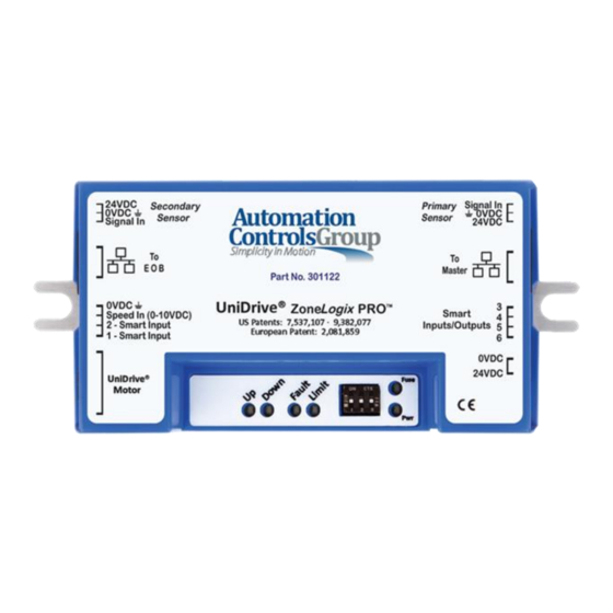
Getting Started and Installation Below is an image of the Zone Controller and the various connections. In Basic Mode there are a few operational mode settings that can be made via Smart I/O settings which are described later in this manual. - Page 9 3) Smart I/O: General purpose, 24 VDC I/O, that can be used as an extension of a PLC, or configured to one of several built-in functions Phoenix Contact, 4-pos plug, 1881341 4) UniDrive Motor Connection: Motor connection for any UniDrive Brushless DC Motor.
-
Page 10: Zone Controller Installation
This section describes how to install the ZoneLogix™ PRO and UniDrive motors in the most common ® configuration. 1. Zone Controller Installation 2. Motor Installation 3. DIP Switch Settings 4. Cable Connections 5. System Configuration 6. Diagnostics & Troubleshooting Zone Controller Installation Mount the Zone Controller in a location where the motor cable reaches the connection header without putting strain on the cable connector or the header. -
Page 11: Zone Installation
Zone Installation A typical zone is installed as shown below. Figure 4: The ZoneLogix™ PRO System The motor is typically placed in the middle of the zone • The Primary Sensor is used as the zone photoeye sensor input when package flow is left to right (Forward •... -
Page 12: Figure 5: Unidrive Motor Stopping Distance
Figure 5: UniDrive Motor Stopping Distance ZoneLogix™ PRO Zone Controller User Guide | Revision 1.0 November 2019 | Page 12... -
Page 13: Configuration Dip Switches
Configuration DIP Switches The DIP switches are used to configure the zone type and motor rotation direction in the Forward (normal) flow direction (EOB to Master). NOTE: The DIP switches are read during power-up only. Set the switches, and then apply power to the Zone Controller. Figure 6: Default DIP Switch and Smart I/O NOTE: The direction of rotation is defined as viewed from the back side of the motor with the shaft extending away from the viewer. -
Page 14: 24Vdc Power Connection
+24VDC Power Connection CAUTION! Power must be applied with proper polarity to avoid potentially damaging the Zone Controller. Follow the pinout shown in Table 1 below. The ZoneLogix™ PRO operates from +22 to +28 volts DC power. Make the power connection only after all other connections have been made. -
Page 15: Pnp Photoeye Sensor Connection
PNP Photoeye Sensor Connection Each zone requires an object sensor to detect the objects that are in the zone when they reach the most downstream edge of the zone. In the Forward (normal) flow direction, the Primary Sensor is the downstream sensor. In applications where the conveyor is run in Reverse Flow, the Secondary Sensor then becomes the most downstream sensor. -
Page 16: Smart I/O Connections
Smart I/O Connections The function of each PNP pin depends on the configuration of the Zone Controller. See 2.3 Configuration DIP Switches. Additional functions are available in Advanced Mode. Basic Mode Functions 2.7.1 The following functions only apply when the Master Zone Controller DIP switch settings are configured for Basic Mode. -
Page 17: Advanced Mode Functions
Table 5: Smart I/O Pin Definitions for the Master Zone Controller in Basic Mode I/O Pin: Description: Branch Op Mode 1 In Branch Op Mode 2 In Branch Reverse In Forward Permission/Reverse Request In Forward Request/Reverse Permission Out Branch No-Fault Out Speed In Branch Speed (0-10 VDC Analog In) Table 6: Operating Modes for Smart I/O Pins 1 &... -
Page 18: Led Feedback Indicators
LED Feedback Indicators The ZoneLogix™ PRO Zone Controller provides six (6) LED indicators shown below: Figure 8: LED Definitions To learn more, see Figure 19: Feedback LEDs. ZoneLogix™ PRO Zone Controller User Guide | Revision 1.0 November 2019 | Page 18... -
Page 19: System Schematic And Installation Summary
System Schematic and Installation Summary The following is a system schematic and summary of settings: Figure 9: Schematic Diagram of ZoneLogix™ PRO System A Branch is made up of at least (1) EOB and (1) Master • Forward (normal) package flow is from EOB to Master. See 3.3.3 Controlling Branch Direction for instructions •... -
Page 20: Basic Mode System Operation & Configuration
Basic Mode System Operation & Configuration System Start Up – Apply 24 VDC Power Zone Discovery 3.1.1 When powered on, the Master Zone Controller initiates a Branch discovery process. The Master communicates sequentially to upstream Zone Controllers and initializes each zone. Each zone should have the following LEDs illuminated: The Pwr LED should be illuminated solid •... -
Page 21: Eob Zone Configuration
EOB Zone Configuration Controlling Object Entry – Forward (normal) Flow Direction 3.2.1 Use Smart I/O Pin 4 (Forward Request/Reverse Permission In) to notify the control that there is a package ready for input to the zone. If the zone is empty when this signal is active, it will cause the zone to run. The signal may be provided by any number of alternative sources such as a PLC, a simple switch, a photoeye sensor, etc. -
Page 22: Table 8: Parameters In Basic Mode
Table 8: Parameters in Basic Mode Parameter: Description: Settings: Op Mode The Operational Mode (Op Mode) of a zone defines its Smart I/O Pins 1 & 2 overall function in the branch. • Disable: Zone motor is disabled. To prevent Branch Op Branch Op Branch Operation... -
Page 23: Zone Controller Updates
Zone Controller Updates The ZoneLogix™ PRO system is designed to automatically adjust firmware in the Zone Controllers in order to ensure all zones are at the same firmware revision. This is beneficial because a lot of testing goes into the development of a system, and generally the firmware revision of all controls should remain at the level of test and validation. -
Page 24: Advanced Mode System Configuration
Advanced Mode System Configuration Basic Mode provides a limited number of features. In Advanced Mode, the ZoneLogix™ PRO can be configured in many different arrangements to provide the most versatile material handling control available. When the ZoneLogix™ PRO is configured in Advanced Mode, each zone is configured by the ZoneLogix™ PRO Branch Monitor. -
Page 25: Motor Performance
Motor Performance Below are the typical motor speed/torque curves for ZoneLogix™ PRO at various current limits. Figure 11: Motor Performance Curves ZoneLogix™ PRO Zone Controller User Guide | Revision 1.0 November 2019 | Page 25... - Page 26 ZoneLogix™ PRO Zone Controller User Guide | Revision 1.0 November 2019 | Page 26...
-
Page 27: Breakout Module
Breakout Module The Breakout Module is an optional component to interconnect ZoneLogix™ PRO Branches using standard RJ-45 cabling. The Breakout Module enables additional innovative solutions such as parallel sections and left and/or right spur connections. Figure 12: Breakout Module (Product 300332) A connection is typically made from a ZoneLogix™... -
Page 28: Figure 13: Handshaking Signals Showing Forward And Reverse Flow Request / Permission Signals
Figure 13: Handshaking Signals Showing Forward and Reverse Flow Request / Permission Signals Figure 14: Handshaking Signals Showing Both Forward / Reverse Request / Permission Signals Figure 15: Internal Diagram of the Breakout Module ZoneLogix™ PRO Zone Controller User Guide | Revision 1.0 November 2019 | Page 28... -
Page 29: Breakout Module Example: Connect Two Branches
Breakout Module Example: Connect Two Branches This example shows a connection between two Branches. The Master on the left is connected to ‘ A ll Signals’. This refers to the fact that the RJ45 cable contains two communication systems; Branch Serial Communications (Master-to- Zones) and Handshaking (Zone-to-Zone). -
Page 30: Breakout Module Example: Transfer Application
Breakout Module Example: Transfer Application This example shows the setup of a transfer in a Branch. Based on the package flow, this Branch is going in the Forward direction … EOB to Master. The Breakout Modules are used to break the Handshaking and allow the serial communications to pass through. -
Page 31: Diagnostics & Troubleshooting
Diagnostics & Troubleshooting Feedback LEDs The ZoneLogix™ PRO Zone Controller provides six (6) LED indicators as shown in Figure 8: LED . Figure 19: Feedback LEDs The Down LED is normally off, but blinks at a ½ sec rate when the optional Branch Monitor is connected to the Master Fuse LED (Red) 8.1.1... -
Page 32: Fault Led (Red)
Fault LED (Red) 8.1.2 Table 9: Fault LED Fault LED Description No fault is present Zone Communications, Invalid Branch Configuration, 1 flash (in 5 sec) or Unsupported Zone Controller in Branch Power input over voltage … reduce voltage. 2 flashes (in 5 sec) Proper range is 22-28 VDC. -
Page 33: Firmware Version Display
Firmware Version Display Three (3) of the feedback LEDs are used to communicate the firmware revision of the Zone Controller during the start- up sequence. Each time that power is applied to the board, the green (power) and (fault) LEDs light up immediately. -
Page 34: Appendix A: Operating Modes
Appendix A: Operating Modes A.1. Singulate (ZPA) Figure 21: Singulate (Singulate Mode) Package 2 will be held in Zone 3 and not allowed to enter Zone 2 until Package 1 has cleared the Zone 2 sensor. A.2. Slug Figure 22: Slug (Slug Mode) All zones will run in this mode if the Sleep Timer has not expired, however if Zone 2 is in accumulation it will stop Zone 3. -
Page 35: A.3. Zip
A.3. ZIP Figure 23: ZIP (Operating Mode) Zone 3 will have permission to release Package 2 into Zone 2 once Package 1 has hit zone 2 sensor. A.4. Zone Hold Figure 24: Zone Hold (Singulate, ZIP, and Slug Modes) If Zones 2 and 3 were put into Zone Hold, Package 2 will be held in Zone 3 when it is detected by the Zone 3 sensor. Zone 2 would attempt to hold Package 1, however depending on Package 1 position at the time it may be pulled into Zone 1.
Need help?
Do you have a question about the UniDrive ZoneLogix PRO and is the answer not in the manual?
Questions and answers