Table of Contents
Advertisement
Quick Links
Advertisement
Table of Contents

Related Manuals for Tektronix P6022


Summary of Contents for Tektronix P6022
- Page 1 Instruction Manual P6022 Current Probe 070-0948-03 Warning The servicing instructions are for use by qualified personnel only. To avoid personal injury, do not perform any servicing unless you are qualified to do so. Refer to all safety summaries prior to...
- Page 2 Instrument Serial Numbers Each instrument manufactured by Tektronix has a serial number on a panel insert or tag, or stamped on the chassis. The first letter in the serial number designates the country of manufacture. The last five digits of the serial number are assigned sequentially and are unique to each instrument.
- Page 3 Tektronix, with shipping charges prepaid. Tektronix shall pay for the return of the product to Customer if the shipment is to a location within the country in which the Tektronix service center is located.
-
Page 5: Table Of Contents
........Repairing the Termination ......P6022 Instruction Manual... - Page 6 Replaceable Electrical Parts Parts Ordering Information ....... Using the Replaceable Parts List .
-
Page 7: General Safety Summary
Do Not Operate with Suspected Failures If you suspect there is damage to this product, have it inspected by qualified service personnel. Do Not Immerse in Liquids Clean the probe using only a damp cloth. Refer to cleaning instructions. P6022 Instruction Manual... - Page 8 Safety Terms and Symbols Terms in This Manual These terms may appear in this manual: WARNING Warning statements identify conditions or practices that could result in injury or loss of life. CAUTION Caution statements identify conditions or practices that could result in damage to this product or other property.
-
Page 9: Service Safety Summary
P6022 Current Probe Service Safety Summary Only qualified personnel should perform service procedures. Read this Service Safety Summary and the General Safety Summary before performing any service procedures. Do Not Service Alone Do not perform internal service or adjustments of this product unless anoth er person capable of rendering first aid and resuscitation is present. - Page 10 Safety...
-
Page 11: Operator Information
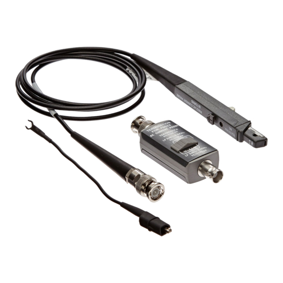
1 MW input impedance. The P6022 probe comes with a passive termination that matches oscilloscope and probe impedance, optimizes the probe performance, and provides two sensitivity settings. In the standard configuration, the P6022 probe comes with a 5 foot cable and termination. The following option is also available. Option 03... -
Page 12: Attaching The Probe And Termination To An Oscilloscope
CAUTION To avoid damaging the probe, do not disconnect the probe ter mination and leave the P6022 clamped around the conductor when measuring high currents. Leaving the probe cable unterminated can cause a high voltage to develop in the secondary winding which may damage the current probe transformer. -
Page 13: Using The Standard Accessories
Your P6022 is shipped with the following accessories: This instruction manual Read these instructions to familiarize your self with the features, specifications, and operation of the P6022 current probe. 6 inch ground lead Use the 6 inch ground lead to ground the shield around the probe transformer at the probe end of the cable. -
Page 14: Operating Considerations
Considerations Features and Controls Sensitivity Control The P6022 termination has a control that allows you to select probe sensitivity. The switch has two positions: 1 mA/mV and 10 mA/mV. When the control is in the 1 mA/mV position, the oscillo scope displays 1 mV for every 1 mA of current in the circuit under test. -
Page 15: Insertion Impedance
When you insert a conductor into the probe, you add impedance to the circuit you are measuring. This additional impedance affects signals; this is particularly important if you are measuring fast rise times. Figure 2 illustrates the equivalent circuit with additional impedance introduced by the P6022. 0.6 mH 0.2 nH .025 W... -
Page 16: Probe Shielding
Probe Shielding The P6022 is shielded to minimize the effect of external magnetic fields. However, strong fields can interfere with the current signal being measured. If you suspect that an external field is interfering with your measurement, remove the probe from the conductor, but keep it in the same location as when you made the suspect measurement. -
Page 17: Service Information
Service Information Warranted This section lists the various warranted characteristics that describe the P6022 Current Probe. Included are warranted electrical and environmental Characteristics characteristics. Warranted characteristics are described in terms of quantifiable performance limits which are warranted. The electrical characteristics listed in Table 1 apply under the following... - Page 18 Table 2: Warranted Environmental Characteristics Characteristic Information Temperature range: Operating -0°C to +50°C Nonoperating -40°C to +65°C Altitude Operating To 2,000 m (6,561 ft), <300 V CAT I To 4,572 m (15,000 ft), <150 V CAT II Nonoperating To 15,240 m (50,000 ft) Table 3: Maximum Ratings Characteristic Information...
- Page 19 Part 1: General Requirements Safety requirements for electrical equip ment for measurement, control, and lab oratory test EN 61010 2 032:1995 Part 2 032: Particular requirements for hand held current clamps for electrical measure ments and test P6022 Instruction Manual...
- Page 20 Table 4: Certifications and Compliances (Cont.) Installation Category Descriptions Terminals on this product may have different installation category designations. The installation categories are: CAT III Distribution level mains (usually perma nently connected). Equipment at this level is typically in a fixed industrial loca tion CAT II Local level mains (wall sockets).
-
Page 21: Typical Characteristics
Typical This section lists the various typical characteristics that describe the P6022 Current Probe. Included are typical electrical and mechanical characteris Characteristics tics. Typical characteristics are described in terms of typical or average perfor mance. Typical characteristics are not warranted. -
Page 22: Circuit Description
As indicated on the probe body, the turns ratio of the P6022 is 50:1. This refers to the number of windings in the secondary of the probe transformer. - Page 23 SW30 SPRING RETURN TO NORMALLY CLOSED POSITION 1mA/mV 17.5 mH FERRITE SW20 13.7 TRANSFORMER CORE (2T) 5-25 (2T) 5-25 10mA/mV 64 mH 10.2 10.5 1.5k 63.4 SHIELD P6022 PROBE P6022 PASSIVE TERMINATION Figure 4: P6022 Schematic Diagram P6022 Instruction Manual...
-
Page 24: Performance Verification
This section provides procedures to check the performance of the P6022, or to calibrate it. These procedures require the equipment listed in Table 7. Specifications given are the minimum necessary for accuracy. If equipment is substituted, it must meet or exceed the specifications of the recom mended equipment. - Page 25 Output amplitude into 50 W Amplitude accuracy 1% from 250 kHz to 150 MHz Termination, feedthrough BNC 50 W Tektronix Part No. 011 0049 01 Attenuator, BNC 5X, 50 W Tektronix Part No. 011 0060 02 Attenuators, BNC 10X, 50 W Tektronix Part No.
-
Page 26: Adjustment Procedures
Procedures 1. Insert a small screwdriver between the cover and the termination near the part number, and gently pry up the top cover only from the P6022 termination by twisting the screwdriver. Leave the bottom cover on, as it must remain in place whenever the termination is in use. -
Page 27: Adjust Aberrations
Step 2: Set the calibration generator to Fast Rise. Step 3: Connect the P6022 cable BNC connector to the termination. Step 4: Connect the P6022 termination to the oscilloscope Ch 1 input. Step 5: Set the P6022 termination sensitivity to 1 mA/mV. - Page 28 Step 14: Check again to make sure that the aberrations are within the specifications described in Step 9. Repeat any adjustments required. NOTE Aberration characteristics do not include the effects of the test oscilloscope. P6022 AC CURRENT PROBE TEKTRONIX, INC. 50 TURNS Figure 6: Location of Probe Adjustments...
-
Page 29: Check Sensitivity
Step 1: Set the oscilloscope time/division to 10 ms. Step 2: Set the oscilloscope vertical deflection to 10 mV/div. Step 3: Check that the P6022 termination sensitivity is set to 1 mA/mV. Step 4: Disconnect the P6022 termination from the oscilloscope. -
Page 30: Check Low Frequency Response
Check Low Frequency Response Step 1: Connect the current probe calibration fixture to the FG 501A function generator output using the appropriate adapter. Step 2: Connect the probe to the current probe calibration fixture. Step 3: Set the termination sensitivity to 1 mA/mV. Step 4: Set the function generator for a 50 kHz sine wave output. -
Page 31: Check High Frequency Response
Step 17: Check that the sine wave generator frequency is 100 MHz. (If you are using an oscilloscope with a bandwidth t200 MHz, the re sponse may be t100 MHz.) When you are done, disconnect all test equipment and replace the termina tion cover. P6022 Instruction Manual... -
Page 32: Maintenance
Maintenance The information in this section will help you maintain your probe for a long service life. Cleaning To clean the probe body, use a soft cloth dampened in a solution of mild detergent and water. To clean the core, open the jaw and clean the exposed core surfaces with a cotton swab dampened with isopropyl alcohol (isopro panol) or ethyl alcohol (fotocol or ethanol). - Page 33 Step 4: Slowly lift the upper half of the probe body slightly at the cable end and push the assembly forward over the nose and off. Step 5: Remove the small ball bearing from the detent in the slide switch. P6022 Instruction Manual...
-
Page 34: Repairing The Probe
Step 6: Lift the back of the return spring retainer out of the holder. Step 7: Remove the slide switch, spring retainer, and the top of the transformer as a unit. Notice the orientation of the movable portion of the transformer in the slide. - Page 35 Step 5: Replace the circuit board by reversing the above procedure. Step 6: Align the switch with the slider in the front cover and replace the front cover. P6022 Instruction Manual...
- Page 36 Service Information...
-
Page 37: Replaceable Electrical Parts
Replaceable Electrical Parts Parts Ordering Replacement parts are available from or through your local Tektronix, Inc. service center or representative. Information Changes to Tektronix instruments are sometimes made to accommodate improved components as they become available and to give you the benefit of the latest circuit improvements. - Page 38 A2 with its subassemblies and parts). Chassis mounted parts have no assembly number prefix and are located at the end of the electrical parts list. Tektronix Part No. (column 2 of the parts list) Indicates part number to be used when ordering replacement part from Tektronix.
- Page 39 Indicates the code number of the actual manufacturer of the part. (Code to name and address cross reference can be found immediately after this page.) Mfr. Part No. (column 7 of the parts list) Indicates actual manufacturer's part number. P6022 Instruction Manual...
- Page 40 Serial No. Mfr. Number Part No. Effective Dscont Name & Description Code Mfr. Part No. 670-1112-00 CIRCUIT BD ASSY:PROBE 80009 670111200 011-0106-00 TERMN,COAXIAL:P6022 80009 011010600 670-1112-00 CIRCUIT BD ASSY:PROBE 80009 670111200 A1C10 283-0157-00 CAP ,FXD,CER DI:7PF,5%,50V 04222 SR155A7R0DAA A1L10 120-0285-00...
- Page 41 A1L10 A1C10 A1R10 A1T14 Figure 9: P6022 Probe Component Location A2L26 A2C26 A2C37 A2SW30 A2C21 A2R33 A2R37 A2R26 A2L28 A2R29 A2C28 A2R28 A2R39 A2R31 A2R34 A2L33 A2C29 A2R36 A2R35 Figure 10: P6022 Termination Component Location P6022 Instruction Manual...
- Page 42 7741 N BUSINESS PARK DR TUCSON AZ 85740-7144 PO BOX 37144 79727 C-W INDUSTRIES 130 JAMES WAY SOUTHAMPTON PA 18966-3818 80009 TEKTRONIX INC 14150 SW KARL BRAUN DR BEAVERTON OR 97077-0001 PO BOX 500 91637 DALE ELECTRONICS INC 2064 12TH AVE COLUMBUS NE 68601-3632...
-
Page 43: Replaceable Mechanical Parts
Replaceable Mechanical Parts This section contains a list of the mechanical parts that are replaceable for the P6022. Use this list to identify and order replacement parts. Parts Ordering Replacement parts are available from or through your local Tektronix, Inc. - Page 44 Fig. & Index Tektronix Serial No. Mfr. Part No. Effective Dscont 12345 Name & Description Code Mfr. Part No. 11 - -------- P6022,PROBE,CURRENT:120 MHZ,100A,5FT W/TERM 204-0360-01 .BODY,PROBE:UPPER 80009 204036001 214-0581-00 .BALL,DETENT:0.062 DIA STEEL 80009 214058100 351-0174-00 .SLIDE,TEST PROD:ACETAL 80009 351017400 214-0735-00 .SPRING,HLCPS:0.12 OD X 1.5 L,OPEN...
- Page 45 Figure 11: P6022 Exploded View P6022 Instruction Manual...
- Page 46 SPECIALTY CONNECTOR CO INC 2100 EARLYWOOD DR FRANKLIN IN 46131 PO BOX 547 8X345 NORTHWEST SPRING & MFG CO 5858 WILLOW LANE LAKE OSWEGO OR 97034-5343 80009 TEKTRONIX INC 14150 SW KARL BRAUN DR BEAVERTON OR 97077-0001 PO BOX 500 Replaceable Mechanical Parts...
-
Page 47: Index
8 Compliances, 9 maximum DC saturation, 11 continuous current, maximum, 8 maximum input voltage, 8 ground clips, using, 2 current flow, direction, 4 maximum pulse current, 8 ground lead, 6 inch, 3 current vs. frequency derating, 9 P6022 Instruction Manual... - Page 48 mechanical parts list, 33 R10, 18 termination, 1, 2 adjustments, 17 19 R12, 18 circuit description, 12 13 R36, 19 repair, 24 26 replacing circuit board, 25 Option 03, 1 repairing replacing connectors, 24 probe, 24 options, cable, 9 foot, 1 termination, 24 26 test equipment, 15 oscilloscope, 1...
- Page 49 Test Probes Click to view products by manufacturer: Tektronix Other Similar products are found below : 6214 6265 6474 815003 923832-BK-B P-KIT-1 R941850000 923837-YL-B 925250-R 72923-2 923848-C 973368101 972318101 972318100 MXHQ87WJ3000 66.9115-23 850182 TAS90 VL1735/45 973368100 972327100 972327101 975017700 975018700...
Need help?
Do you have a question about the P6022 and is the answer not in the manual?
Questions and answers