Table of Contents
Advertisement
Quick Links
JM Oil Lubrication Pump
Multi-line pumps and multi-line units
for oil total loss lubrication systems in compressor design
Original operating instructions
for partly completed machinery
Assembly instructions
acc. to EC Dir. 2006/42/EC
for partly completed machinery with associated operating instructions
acc. to 98/37/EC, Annex II B
EN
Advertisement
Table of Contents

Related Manuals for SKF JM Series


Summary of Contents for SKF JM Series
- Page 1 JM Oil Lubrication Pump Original operating instructions acc. to 98/37/EC, Annex II B for partly completed machinery Multi-line pumps and multi-line units Assembly instructions acc. to EC Dir. 2006/42/EC for oil total loss lubrication systems in compressor design for partly completed machinery with associated operating instructions...
- Page 2 JM Oil Lubrication Pump Unit Service If you have technical questions, please contact Masthead © SKF Lubrication Systems Germany AG the following addresses: The original assembly instructions with as- This documentation is protected by copyright. SKF Lubrication Systems Germany AG...
-
Page 3: Table Of Contents
Page 3 Table of contents Assembly instructions Operating manual Information concerning EC Declaration 1. Safety instructions 7. Shutdown 7.1 Temporary shutdown of Conformity and 2. Lubricants EC Declaration of Incorporation 3. Transport, delivery, and storage 7.2 Permanent shutdown Explanation of symbols and signs 3.1 Lubrication units 8. -
Page 4: Information Concerning Ec Declaration Of Conformity And
Within the scope of application of the EC When used in conformity with their intended 2004/108/EC Directive, commissioning shall be prohib- use, the products supplied by SKF Lubrication ited until the machinery in which this Systems Germany AG do not reach the limit Notes: part is installed conforms with the provi- values listed in Article 3, Para. -
Page 5: Explanation Of Symbols And Signs
Explanation of symbols Page 5 Explanation of symbols and signs Instructions placed directly on the machines/ You will fi nd these symbols, which warn of grease lubrication pump units, such as: specifi c dangers to persons, material assets, or Arrow indicators the environment, next to all safety instructions You are responsible! Labels for fl uid connections must be... -
Page 6: Safety Instructions
Risks may, however, arise from The use of synthetic oils requires prior ap- its usage and may result in physical harm to proval from SKF Lubrication System. persons or damage to other material assets. Therefore the product may only be used in... - Page 7 Assembly instructions Page 7 1.2 Authorized personnel 1.3 Electric shock hazard 1.4 System pressure hazard Only qualifi ed technical personnel may install, Electrical connections for the described prod- Lubrication systems are pressurized operate, maintain, and repair the products uct may only be established by qualifi ed and during operation.
-
Page 8: Lubricants
Directive 67/548/EEC, Article 2, Para. 2, may considerations. the machine/system in cooperation with the only be fi lled into SKF centralized lubrication lubricant supplier. systems and components and delivered and/or The bearings/friction points that require lubri-... - Page 9 For example, synthetic lu- ized lubrication system. bricants may be incompatible with elastomers. Different lubricants must not be mixed, Please contact SKF Lubrication Systems if you 2.4 Lubricants and the environment as mixing may result in damage and have further questions regarding lubricants.
- Page 10 Assembly instructions Page 10 2.5 Lubricant hazards Centralized lubrication systems must always be free of leaks. Leaking lubricant is hazardous due to the risk of slipping and injury. Beware of any lubricant leaking out during assembly, operation, maintenance, and repair of centralized lubrication systems.
-
Page 11: Overview
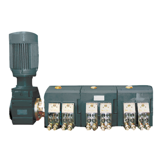
Assembly instructions Page 11 3. Overview Item description Fig. 1 Pump drive 2 Pump body 3 Pump housing/oil container 4 Pump outlets (max. 2x pump body) 5 Oil level check 6 Sight glass 7 Delivery volume setting screw... -
Page 12: Assembly
Assembly instructions Page 12 4. Assembly 4.1 Information on assembly The product should be protected from humid- During assembly and especially when drilling, On the pump units' electrical connections, it ity and vibration, and should be mounted so always pay attention to the following: must be ensured that appropriate measures that it is easily accessible, allowing all further prevent interference between signals due... -
Page 13: Assembly Of The Jm Oil Lubrication Pump Unit
Assembly instructions Page 13 4.2 Assembly of the JM oil lubrication pump unit 4.2 Setup and attachment 4.2.1 Assembly The JM grease lubrication pump must be The assembly of the pump housing Warning! installed on a level surface. The pump's base Pump bodies that are not in use should of the JM oil lubrication pump is done using plate must not be under stress. -
Page 14: Mounting Dimensions
Assembly instructions Page 14 4.2.2 Mounting dimensions 4.2.3 Assembly holes Fig. 2 Number of Capacity Outlets housings [n] [liters] max. [n] 1140 1330... -
Page 15: Use
Assembly instructions Page 15 4.2.4 Use 4.2.5 Housing versions 4.3 Drive versions The JM oil lubrication pump is a high-pressure The JM pump consists of 1 to 7 pump hous- 4.3.1 Standard design pump that produces a maximum continuous ings (individual reservoirs) with 1 to 4 outlets operating pressure of 600 bar per outlet. -
Page 16: Jm Rotary Drive
Assembly instructions Page 16 4.3.2 Rotary drive G 3/8" threads for inlet and A - A Drive position A outlet on pressure-tight reservoirs Drive position B Illustration rotated by 180° 65,5 A - A... - Page 17 Operating viscosity ....25 to 3000 mm 1) At operating pressure > 400 bar and an operating viscosity < 100 mm please contact the SKF service center. 2) Please inquire before using synthetic lubricants.
-
Page 18: Jm Rotary Drive With
Page 18 Assembly instructions 4.3.3 Rotary drive with gear train (164) 8,5* 124*/169** ca. 154** 563* / 608** * = without prelubrication ** = with prelubrication Drive position "C" Drive position "E" Drive position "D" Drive position "F"... -
Page 19: Gear Train
Number of outlets ... . . 1 to 28 1) At operating pressure > 400 bar and an operating viscosity < 100 mm please contact the SKF service center. Delivery volume adjustment 2) Please inquire before using synthetic lubricants. -
Page 20: Jm Electric Motor Drive With Gear Train
Assembly instructions Page 20 Ø120 4.3.4 Electric motor drive with gear train 8,5* 124*/169** 124*/169** 574* / 619** ca. 154** Drive position G Drive position H "G" Illustration rotated by 180° Ø160*** Ø120 8,5* 124*/169** 124*/169** 574* / 619** ca. 154** * = without prelubrication View A ** = with prelubrication... - Page 21 Assembly instructions Page 21 4.3.4 Electric motor drive with gear train Technical data General Motor Mounting position ... . . Horizontal, level surface Type ......B14/V18 Reservoir capacity .
- Page 22 Assembly instructions Page 22 4.3.5 Delivery volumes with electric motor drive The delivery volume depends on the rated speed, motor make, gear train, gear ratio, pump elements and settings. Characteristics at delivery volumes of 0.07, 0.1 and 0.2 cm /piston strokes Motor Gear train Pump element...
- Page 23 Assembly instructions Page 23 Note The delivery rate figures are based on motor designs with a mains frequency of 50 Hz. The delivery rate figures are increased by 20% at a mains frequency of 60 Hz. The figures for dimensions, delivery rates, and power consumption refer to standard VEM motors. If other makes are used, deviations have to be expected.
-
Page 24: Lubrication Line Arrangement
Page 24 Assembly instructions 4.4 Lubrication line arrangement When arranging the main and secondary sive pressure by means of a pressure-limiting gentle transitions. Sudden changes of direc- lubricant lines, observe the following instruc- valve. tion should be avoided if possible. tions in order to ensure that the entire lubri- All components of the lubrication line system cation system functions smoothly. -
Page 25: Note On The Rating Plate
Assembly instructions Page 25 4.7 Note on the rating plate The rating plate on the oil lubrication pump unit provides important data such as the type designation, order number, barcode, and serial number. To avoid loss of this data in case the rating plate becomes illegible, these characteristics should be entered in the following table. - Page 26 Page 26 Assembly instructions Warning! Information beyond the actual as- sembly procedure is contained in the included operating instructions. The assembly and operating instructions are therefore considered an inseparable part of the documentation. The operating instructions are divided into the chapters: 1.
-
Page 27: Operating Manual
Page 27 JM Oil Lubrication Pump Original operating instructions acc. to 98/37/EC, Annex II B for partly completed machinery Multi-line pumps and multi-line units Operating instructions associated for oil total loss lubrication systems in compressor design with assembly instructions according to EC Dir. 2006/42/EC for partly completed machinery... -
Page 28: Safety Instructions
General Warning! Warning! Disclaimer of liability These operating instructions must be SKF Lubrication Systems shall not be held The information on lubricants listed in read and properly understood by the liable for damages: Chapter 2, "Lubricants," of the assem- assembler and the responsible techni-... -
Page 29: Transport, Delivery, And Storage
Light: avoid direct sun or UV ments. The packaging material must be kept exposure and shield until any discrepancies are resolved. nearby sources of heat SKF Lubrication Systems products are subject to the following storage conditions:... -
Page 30: Assembly
The product can also be returned to instructions are contained later in this chapter. The pump housings can optionally be mount- SKF Lubrication Systems for disposal, ed on a common oil reservoir. They are avail- in which case the customer is respon- 4.2 Assembly of the JM multiline pump unit... -
Page 31: Design And Function
5. Design and function Page 31 5. Design and function 5 Function See fi gure 4 The delivery volume can be reduced to almost Fig. 4 The pump shaft (1) imparts the required zero. In addition to the position of the setting stroke motion to both the feed piston (2) and screw, the delivery volume depends on the the working piston (3). -
Page 32: Commissioning
Page 32 6. Commissioning / settings 6. Commissioning 6.1 Condition on delivery The JM oil lubrication pump unit is delivered Switch on the oil lubrication pump Turn setting screw (12) to position "8" with all its setting screws set for full stroke to full stroke facilitate venting of the pump. -
Page 33: Delivery Rate Of Pump Elements
6. Commissioning / settings Page 33 6.4 Delivery rate of the pump elements 6.6 Determination of delivery rate 6.7 Startup of pump after long downtime The delivery rate of the pump elements can The delivery volume can be easily determined The following is to be performed be set using the key figures engraved between and/or set as follows:... -
Page 34: Shutdown
Chapters "Assembly" and lubricants. "Commissioning" in the assembly instructions The product can also be returned to SKF Lu- and operating instructions. brication Systems for disposal, in which case the customer is responsible for reimbursing... -
Page 35: Maintenance
SKF Lubrication Systems shall not be held before opening any of the product's mended. liable for damages resulting from improperly components. -
Page 36: General Information
Page 36 8. Maintenance 8. Maintenance 8.1 General Maintenance Operating Check Change item hours The oil level is to be checked after each 1000 Oil lubrication 1000 Visual inspection operating hours for JM oil lubrication pumps pump with gear trains. The gear train has to be fi lled with gear oil up to the threading of the screw 8,5* Gear train... -
Page 37: Malfunctions
Work on products that have not been The hot surface of a motor may cause Contact the Service department of SKF de-energized may result in bodily burns. Motor surfaces may only be Lubrication Systems if you cannot remedy the injury. -
Page 38: Commissioning Malfunctions
Page 38 9. Faults/problems 9.1 Commissioning malfunctions Warning! In cases of functional failure, always make sure that all technical specifi cations have been complied with in the existing operating conditions. Malfunction Cause Remedy No delivery Pump not vented - Vent the pump element - See 6.3 - Check the power supply Motor stopped (see rating plate for electric motor... -
Page 39: Spare Parts
10. Spare parts Page 39 10. Spare parts Arbitrary alterations and manufacture of spare parts Device rebuilding or modifi cation is only permitted with manufacturer's agree- ment. Original spare parts and acces- sories, which are authorized by the manufacturer, serve to ensure safety. The use of other parts shall serve to eliminate any liability for consequences thereof. - Page 40 But no liability can be accepted for any loss or damage, whether direct, indirect or consequential arising out of use of the information contained herein. All SKF products may be used only for their intended purpose as described in these assembly instructions with associated operating instructions. If assembly/operating instructions are supplied together with the products, they must be read and fol- lowed.
Need help?
Do you have a question about the JM Series and is the answer not in the manual?
Questions and answers