Table of Contents
Advertisement
Quick Links
Advertisement
Table of Contents

Subscribe to Our Youtube Channel
Related Manuals for Tatu Marchesan SDA3


Summary of Contents for Tatu Marchesan SDA3
- Page 1 SDA³ SDA³ SDA³ E SDA³ E OPERATOR’S MANUAL...
- Page 2 IDENTIFICATION Dealer: Owner: Firm / Farm: City: State: No. of the Certificate of Guarantee: Serial / No.: Date: Invoice No.: Product: Notes:...
- Page 3 Introduction This operator's manual helps on the assembly process and provides the necessary information for the correct operation and maintenance, thus assuring a higher yield, safety and durability. This manual contains the necessary information for the best performance of your equipment. The operator and the maintenance staff must carefully read the entire manual before working with the equipment.
- Page 4 Table of contents 1. To the owner 2. To the operator 5 to 15 Working safety standards 3. Data sheet 16 to 19 Intended use of the equipment / Prohibited use of the equipment Equipment dimensions 18 & 19 4. Components 20 &...
-
Page 5: Table Of Contents
Table of contents 9. Optional 61 to 85 Row markers with hydraulic cylinder Hydraulic activation assembly - SDA³ Hydraulic circuit with single oil distributor 63 & 64 Hydraulic activation assembly - SDA³E Hydraulic circuit with double command 66 to 68 Row markers 69 &... - Page 6 1. To the owner The acquisition of any Tatu product assures to the original purchaser the following rights: - Warranty certificate; - Operator's manual; - Technical assistance by the dealer on equipment delivery. However, the owner must check the condition of the equipment on delivery, as well as knowing the warranty terms.
- Page 7 2. To the operator Be careful with the environment Dear operator! Respect the ecology. Do not throw trash away. This gesture of goodwill helps to protect our environment. Products such as oil, fuel, filters, batteries and others are spilt over the soil and can penetrate to the underground layers, compromising nature.
- Page 8 2. To the operator Working safely Never use your bare hands to check hydraulic leaks, the high pressure can cause injuries. Never attempt to change the adjustments, clean or lubricate the equipment when the same is switched on or in movement. Be careful while driving on slopes.
- Page 9 2. To the operator Working safely Have extreme caution when operating with the power take-off (PTO), which you should not get closer during operation. The presence of any other people on the tractor or equipment is stricly forbidden. Have extreme caution when driving under electrical power lines. Any contact may result in severe shocks, injuries or death.
- Page 10 2. To the operator Personal protective equipment (PPE) The personal protective equipment must be used as stated by the Ministry of Labor The personal protective equipment must be used as stated by the Ministry of Labor and Employment on the working standards. and Employment on the working standards.
- Page 11 2. To the operator General and mandatory safety measures 1. Only trained and qualified personnel are allowed to operate the equipment. 2. While working or during transportation, only the presence of the operator is allowed on the tractor. 3. Do not allow any passengers on the equipment. 4.
- Page 12 2. To the operator General and mandatory safety measures 14. Always shut down the engine, remove the key and use the handbrake before leaving the tractor seat. 15. Fasten the safety chain between the tractor and equipment. 16. Only pull the equipment using a tractor with appropriate power. 17.
- Page 13 2. To the operator Transportation over truck or trailer Marchesan does not advise the equipment traffic on highways, because this practice involves serious security risks in addition to being prohibited by the current existing traffic law. The transportation for long distances should be done on truck, trailer or others by following these safety guidelines: 1.
- Page 14 2. To the operator Working safety standards It is important to have knowledge not only about the functioning, operation of the equipment and its technology, but also the working legal aspects when using the equipment, such as: safety standards, operator's manual and working safety. The equipment and tools used on the rural area must be properly handled, otherwise health and safety of involved personnel may be compromised.
- Page 15 2. To the operator Safety decals The safety decals warn about the equipment points that require more attention and they should be kept in good repair. If these decals become damaged or illegible, replace them. Marchesan provides decals, upon request and indication of the respective serial number. P P E E R R I I G G O A A D D V V E E R R T T Ê...
- Page 16 2. To the operator Safety decals RECÂMBIO DE ENGRENAGENS RECÂMBIO DE ENGRENAGENS RECÂMBIO DE ENGRENAGENS RECÂMBIO DE ENGRENAGENS SPROCKET COMBINATIONS SPROCKET COMBINATIONS SPROCKET COMBINATIONS SPROCKET COMBINATIONS CAMBIO DE ENGRANAJES CAMBIO DE ENGRANAJES CAMBIO DE ENGRANAJES CAMBIO DE ENGRANAJES SEEDS ADUBO FERTILIZER ABONO SEMENTE...
- Page 17 Number 5 decal 05.03.03.3419 Number 7 decal 05.03.03.3421 05.03.03.3423 Number 9 decal SDA3 decal 05.03.03.3885 SDA3 E decal 05.03.03.3871 Tatu hopper logotype (250 x 1200) 05.03.03.3875 Tatu hopper logotype (190 x 255) 05.03.03.3853 05.03.03.1942 Manual seal decal 1" coil pitch auger decal (15 - 23)* 05.03.03.0897...
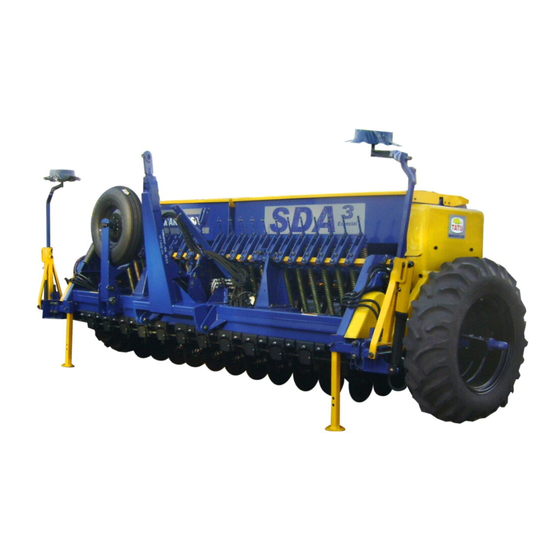
- Page 18 3. Data sheet Intended use of the equipment The no-till seed drill models SDA³ and SDA³ E are designed to perform the plantation of several small grains, such as: wheat, rice, soybean, oats, barley and others. They feature a better uniformity in the seeds and fertilizer distribution, greater versatility during operations and proper fittings to your needs as the main advantages.
- Page 19 3. Data sheet SDA³ - No-till seed drill SDA³ Hoppers capacity # of Spacing Tractor Height (liters) between disc Length (mm) required (mm) units blades power (cv) Seeds Fertilizer 80 - 90 90 - 95 1850 4000 95 - 105 95 - 105 NOTE - SDA³...
- Page 20 3. Data sheet Equipment dimensions SDA³ / SDA³ E - Rev.04 - Mar / 22...
- Page 21 3. Data sheet Equipment dimensions Working Weight Frame width (mm) (mm) (mm) (mm) (mm) (mm) (kg) 15 row units 2212 4000 3780 2794 19 row units 2844 4000 4570 3310 21 row units 3500 4000 5200 3612 1850 2300 2500 23 row units 3476 4000...
- Page 22 4. Components Fully assembled 01 - Frame 02 - Drawbar 03 - Extensor 04 - Fertilizer hopper 05 - Seed hopper 06 - Wheel 07 - Hydraulic circuit 08 - Row marker (optional) 09 - Longitudinal transport (optional) 10 - Hectarimeter (optional) 11 - Open end wrench 12 - Spanner wrench SDA³...
- Page 23 4. Components No-till or conventional sowing 14" disc blades (plain or notched) and 15" x 15" unaligned double discs with two tapered roller bearings in each hub. Press wheels for no-till Press wheels for no-till "V" press wheel "V" press wheel sowing with standard sowing with standard for no-till sowing,...
- Page 24 5. Assembly ATTENTION! - Only QUALIFIED and AUTHORIZED personnel must assemble/disassemble the equipment. - Use safety glasses, earplugs/muffs, protective gloves and any other required PPE. - Avoid direct contact with the lubrication oil and do not throw it away or any other type of oil or grease on the environment.
- Page 25 5. Assembly Hydraulic circuit assembly - tractor with double command The SDA³ hydraulic activation can be done in two ways, according to the owner's option. OPTION 1 - for double command. The coupling of the 04 (four) hoses is directly made in the "female" quick couplers of the tractor.
- Page 26 5. Assembly Hydraulic circuit assembly - tractor with double command Row unit Row unit lifting lifting Row unit Row unit lifting lifting Item Quantity Description Ø 3/8 x 4600 TR-TM hose (Black / Red) Pressure Pressure Ø 3/8 x 4600 TR-TM hose (Black / Blue) Return Return Row unit lifting cylinder...
- Page 27 5. Assembly Triple valve operation Position 1 - To operate both cylinders simultaneously. Position 2 - To operate the right cylinder. Position 3 - To operate the left cylinder. Position 1 Position 1 Position 2 Position 2 Position 3 Position 3 NOTE - Positions 2 and 3 are used to make final touches, allowing to activate just half of the equipment.
- Page 28 5. Assembly Hydraulic circuit assembly - lifting the row units OPTION 2 - for single command On this option, the hydraulic activation is done using a triple valve (flow directioner), being just necessary a single command with rear output: - Fasten the oil distributor (A) to the support located on the frame using a bolt, spring washer and nut;...
- Page 29 5. Assembly Hydraulic circuit assembly - lifting the row units Item Quantity Description Ø 3/8 x 1400 TC-TM hose (Black / Red) Pressure Pressure Ø 3/8 x 3500 TC-TM hose (Black / Blue) Return Return Ø 3/8 x 3300 TC-TC hose Pressure Pressure Ø...
- Page 30 5. Assembly Hydraulic circuit assembly - lifting the wheel supports Wheel support Wheel support Wheel support Wheel support NOTE - If necessary, use thread sealing tape to couple the hoses to the male quick couplers. Check the functioning of the triple valve above. SDA³...
- Page 31 5. Assembly Hydraulic circuit assembly - lifting the wheel supports Item Quantity Description Ø 3/8 x 3500 TC-TM hose (Black / Red) Pressure Pressure Return Return Ø 3/8 x 3500 TC-TM hose (Black / Blue) Ø 3/8 x 2500 TR-TR hose Pressure Pressure Ø...
- Page 32 6. Set-up instructions ATTENTION! RISK OF ACCIDENT - Only CAPABLE and AUTHORIZED personnel must operate the equipment. - Observe every safety condition and use safety glasses, foot protection, earplugs/ muffs, protective gloves and any other required PPE. - Before starting the job or transporting the equipment, check for any people or obstructions on the area.
- Page 33 6. Set-up instructions Preparing the equipment The equipment must always be parked on a dry and flat place, free from any debris or strange objects. Follow this procedure to set the equipment up:Clean up to remove strange objects from the equipment and from the working area; 1.
- Page 34 6. Set-up instructions Hitching to the tractor When hitching or unhitching the seeder to the tractor, carry out this process on a flat and firm location. Fasten the drawbar (A) to the tractor drawbar using a pin (B) and locking with a cotter pin.
- Page 35 6. Set-up instructions Coupling the hydraulic hose to the tractor Before coupling the hoses (A), clean the quick coupler surface. Couple the hoses by pushing the quick coupler on the connections until it locks. The uncoupling is done by pulling the quick coupler; this is the Push/Pull system. Before uncoupling the hoses, shut down the tractor engine and move the levers forward or backward until noting that the cylinder is not activated anymore.
- Page 36 6. Set-up instructions Spacing between row units table The equipment usually leaves the factory assembled with a minimal spacing of 158 or 175 mm for the sowing of wheat, rice, oat and others, but it is possible to use other spacings as shown on the table below.
- Page 37 6. Set-up instructions Positioning the row units on the frame Check if the number of row units to be assembled on the seeder is even or odd and follow the instructions below: "H" spring "H" spring fastener fastener Left row unit Left row unit Right row unit Right row unit...
- Page 38 6. Set-up instructions Procedures to change the spacing To change the spacings of the seeder, proceed as follows: - Change the spacing on a clean, flat and firm location. Make sure that the seeder is properly supported; - Release the row units by loosening the nuts (A and B). Remove only the row units which will not be used, the other ones should be kept or displaced in the equipment;...
- Page 39 6. Set-up instructions Procedures to change the spacing If necessary, displace the hydraulic cylinders (F) along with the supportive bearings (G). To allow the desired spacings, always keep a minimum spacing between the cylinder and the supporting bearing, preventing that the squared axle get forced. To close the fertilizer outlets, just place the chutes (H) over the augers.
- Page 40 6. Set-up instructions Setting the equipment to transport position After coupling the seeder, totally lift the jacks (A). Activate the cylinders (B) to lift the row units. During transportation, always use the rod locks (B) of the hydraulic cylinders. NOTE - It is recommended to fill up the seeder only on the work place.
- Page 41 6. Set-up instructions Procedures before the sowing Before you start sowing, carry out a general inspection of the seeder, retightening all bolts and nuts, also verifying the condition of all pins and cotter in order to prevent future damages. Repeat this operation after the first day of work. NOTE - It is recommended to fill up the seeder only on the work place.
- Page 42 7. Adjustments and operations ATTENTION! - Only QUALIFIED and AUTHORIZED personnel must assemble/disassemble the equipment. - Use safety glasses, earplugs/muffs, protective gloves and any other required PPE. - Avoid direct contact with the lubrication oil and do not throw it or any other type of oil or grease away on the environment.
- Page 43 7. Adjustments and operations Seed distribution table (wheat and rice) Observe, in the following tables, the approximated amount of seeds in kilogram per hectare (kg/ha) for wheat and rice, according to the opening scale and used spacings. Seed distribution table (wheat) Rotor opening = Point 1 (check the 'fine seeds distribution' page).
- Page 44 7. Adjustments and operations Seed distribution table (soybean) Rotor opening = Point 1 (check the 'fine seeds distribution' page). Amount for the different spacings Grams in 50 between row units (kg/ha) Scale meters per row unit 316 mm 350 mm 400 mm 450 mm 500 mm...
- Page 45 7. Adjustments and operations Fertilizer distribution Fertilizer distribution is made by the helical-type auger and different amounts are obtained by the sprocket combinations in the Drive {A} and Driven {B} shafts. To change the sprockets, remove the protection covers on the sides of the equipment. Loosen up the chain tightener (A).
- Page 46 7. Adjustments and operations Fertilizer distribution ATTENTION! - The tables on the following pages indicate the obtained amounts using a 1" coil pitch auger (standard). This auger carries approximately 17 grams of commercial granulated fertilizer at each turn. - The tables on the following pages indicate the obtained amounts using a 2" coil pitch auger (optional).
- Page 47 7. Adjustments and operations Fertilizer distribution table (05.03.03.0897 - 05.03.03.0304) SDA³ / SDA³ E - Rev.04 - Mar / 22...
- Page 48 7. Adjustments and operations Fertilizer distribution table (05.03.03.0894 - 05.03.03.0312) SDA³ / SDA³ E - Rev.04 - Mar / 22...
- Page 49 7. Adjustments and operations Fertilizer distribution table (05.03.03.0893 - 05.03.03.0301) SDA³ / SDA³ E - Rev.04 - Mar / 22...
- Page 50 7. Adjustments and operations IMPORTANT - Data in the previous tables (seed and fertilizer) may vary due to many factors. Therefore, we request that you carefully pay attention to the following topic: Practical test for seeds and fertilizer distribution The most appropriate way to assess the amount of seed and fertilizer to be distributed is on the same field where sowing will be carried out, as follows: - Whenever it is possible, use the same tractor and operator for sowing.
- Page 51 7. Adjustments and operations Auxiliary calculation for seeds and fertilizer distribution In order to distribute other amounts of seed and fertilizer using spacing and areas which are different from those depicted in the tables, we suggest a quick calculation, where all used data can be replaced by data of your own interest using the formula below, which contains the following elements: A = area to be seeded or fertilized (m²).
- Page 52 7. Adjustments and operations Furrow opening The furrow opening is made using unaligned double discs. The disk that has the function to cut the straw (stubble) is the one that is coupled to the rim, the other one performs the furrow opening for the seeds and fertilizer.
- Page 53 7. Adjustments and operations Sowing depth The sowing depth is controlled by activating the hydraulic cylinders, which acts on the axle of the row lift. To keep a constant working depth, use the depth stops (A), which limits the course of the cylinder rods. The depth stops have several sizes and combined they can determine various adjustments points.
- Page 54 7. Adjustments and operations Lateral rim Standard for SDA³ and SDA³E models The rims (A) are coupled to the unaligned double discs, on the disc blades that cut the stubble. The 310 mm rim is standard and comes with the equipment, the others are optionals as described below.
- Page 55 7. Adjustments and operations Fertilizer distribution on soil Special attention should be given to the position of the fertilizer related to the seed, observing mainly the following factors: - Crop type; - Fertilizer type; - Fertilizer amount; - Soil moisture. The detailed knowledge of these factors allow the definition of the best fertilizer positioning related to the seed, avoiding their burning.
- Page 56 7. Adjustments and operations Closing the furrows "V" press tire and iron press wheel. The furrow closing can be made by the press tires (A) or by the iron press wheel (B). Both of them have pressure adjustment over the soil by changing the bolt in the fixation support holes (C) or in the pressure spring (D).
- Page 57 7. Adjustments and operations Operations - important points 1. Retighten nuts and bolts after the first day of work. Check the conditions of pins and cotter pins. Then, retighten every 24 hours of service. 2. Carefully observe the lubrication intervals. 3.
- Page 58 8. Longitudinal transportation Preparing the tractor (three-point hitch) Before starting the operations, prepare the tractor and equipment appropriately. Check the general conditions of the tractor, especially the good functioning of the hydraulic system that must be in flotation mode. The addition of water ballasts on the tires or a set of weights on the tractor front part or on the rear wheels are the most used ways to increase the traction over the soil and to assure a greater stability of the set.
- Page 59 8. Longitudinal transportation Procedures for the longitudinal transportation - hitching to the tractor For hitching, choose a place as flat as possible. Drive the tractor slowly in reverse gear to the planter direction and be ready to brake. When close enough, use the lever to control the hydraulic position, leaving the left lower arm in the same level of the hitch pin.
- Page 60 8. Longitudinal transportation Setting up the longitudinal transportation For hitching to the longitudinal transportation, follow some important steps to avoid damages to the equipment: 1. Totally lift the row units using the cylinders and lock them using the transport locks (A) to avoid that the row units go down;...
- Page 61 8. Longitudinal transportation Setting up the longitudinal transportation 6. After hitching the drawbar (G) to the tractor three-point hitch (as indicated on the 'hitching to the tractor' page on this section), couple it to the right hand side wheel of the equipment using a pin (H), nut and counter nut;...
- Page 62 8. Longitudinal transportation Longitudinal transportation methods When transporting the equipment using the tractor three-point hitch, follow the steps below: 1. Do not transport the equipment if it is loaded; 2. Observe the equipment width related to the narrower spots on the route, especially gates and roads with ditches;...
- Page 63 9. Optional Row markers with hydraulic cylinder Couple the supports (A) to the seeder frames using clamps, flat washers, spring washers and nuts. Couple the marker arms (B) to the supports (A) using bolts (C), bushings, flat washers, spring washers and nuts. Assemble the hydraulic cylinders to the arms (B) and fasten them to the supports (A) using pins and cotter pins.
-
Page 64: Hydraulic Activation Assembly - Sda³
9. Optional Hydraulic activation assembly - SDA³ In this case, the tractor needs a single command (with two rear outputs). - Fasten the oil distributor (A) to the frame using bolts (B), flat and spring washers and nuts; - Assemble the sequence valve (C) to the frame center using bolts (D) and flat and spring washers;... -
Page 65: Hydraulic Circuit With Single Oil Distributor 63
9. Optional Hydraulic circuit with single oil distributor Row marker Row marker Row unit Row unit lifting lifting Row unit Row unit lifting lifting Row marker Row marker NOTE - If necessary, use thread sealing tape to couple the hoses. SDA³... - Page 66 9. Optional Hydraulic circuit with single oil distributor SDA³ 15 and 19 row units Item Quantity Description Return Return Ø 3/8 x 300 TR-TR hose Ø 3/8 x 650 TR-TR hose Return Return Ø 3/8 x 1500 TR-TR hose Return Return Ø...
-
Page 67: Hydraulic Activation Assembly - Sda³E
9. Optional Hydraulic activation assembly - SDA³E In this case, the tractor needs a double command (with four rear outputs). - Fasten the oil distributor (A) to the frame using bolts (B), flat and spring washers and nuts; - Assemble the sequence valve (C) to the frame center using bolts (D) and flat and spring washers;... - Page 68 9. Optional Hydraulic circuit with double command Row marker Row marker Wheel Wheel support support Row unit Row unit lifting lifting Row unit Row unit lifting lifting Wheel Wheel support support Row marker Row marker NOTE - If necessary, use thread sealing tape to couple the hoses. SDA³...
- Page 69 9. Optional Hydraulic circuit with double command Item Quantity Description Return Return Ø 3/8 x 300 TR-TR hose Ø 3/8 x 650 TR-TR hose Return Return Ø 3/8 x 1500 TR-TR hose Return Return Pressure Pressure Ø 3/8 x 2350 TR-TR hose Ø...
-
Page 70: Hydraulic Circuit With Double Command 66 To
9. Optional Hydraulic circuit with double command Item Quantity Description Ø 3/8 x 300 TR-TR hose Return Return Ø 3/8 x 650 TR-TR hose Return Return Ø 3/8 x 1500 TR-TR hose Return Return Ø 3/8 x 2800 TR-TR hose Pressure Pressure Return... -
Page 71: Row Markers 69
9. Optional Row markers Using the row markers is very important to get a plantation with uniform spacing. This is something that will facilitate the cultural treatments and the crop later on. To adjust the marker discs just loose the two bolts (A) which fasten the squared axle and displace all the set until the desired distance. - Page 72 9. Optional Row markers WARNING BEFORE STARTING TO RAISE OR MOVE THE PLANTER, CHECK FOR PEOPLE OR ANIMALS NEAR OR UNDER THE PLANTER, ESPECIALLY IN THE ROW MARKER ACTION AREA. Working angle The marker discs feature angle adjustments to facilitate the soil opening and delimitation. In order to do so, loosen up the nut (B) and adjust as necessary.
-
Page 73: Fine Seeds Hopper
9. Optional Fine seeds hopper Assemble the fine seeds distribution hopper (A) to the seeder hopper (B) using bolts, washers and nuts. Couple the sprocket (C) and the double sprocket on the side of the hoppers. Then, pass the chain (D) through the sprocket (C) and in the first gear of the double sprocket, then pass the chain (D) using the chain tightener (E). -
Page 74: Amount Of Seeds
9. Optional Amount of seeds The amount of seeds to be distributed is determined by the adjusting bushing (A), which activates the rotors opening in the graduated scales. This adjustment is achieved by loosening the lock nuts (B) and turning the adjusting bushing (A), while observing the graduated scale (C). -
Page 75: Lateral Fertilizer Row Unit / Fertilizer Conductor Over Surface
9. Optional Lateral fertilizing row unit (soybean) The TATU seeder models SDA³/SDA³E can perform a lateral and incorporated fertilizing (next to and below the seeds), as required to soybean and other cultures. Fertilizer conductor over surface To make the fertilizing in a surface, Marchesan optionally supplies the external conductors. -
Page 76: Horizontal Metering For Large Seeds
9. Optional Horizontal metering for large seeds Seeking the best performance of the SDA³ and SDA³E seeders, Marchesan optionally supplies the seed metering for large seeds. Minimum spacing allowed = 400 mm. Minimum distance between fertilizer/seed = 20 mm. Components: 01 - Seed row unit 02 - Fertilizer row unit 03 - Wheels to control the seed depth... -
Page 77: Row Units And Spacings Table 75
9. Optional Row units and spacings table Table regarding the number of row units and spacings for using the horizontal metering in the SDA³/SDA³E models. Model Number of row units Spacings (mm) SDA³/SDA³E 15 09** SDA³/SDA³E 19 * The central row units for a 400 mm spacing should be assembled according to the image below. - Page 78 9. Optional Row units and spacings table Table regarding the number of row units and spacings for using the horizontal metering in the SDA³/SDA³E models. Model Number of row units Spacings (mm) 12** SDA³/SDA³E 21 SDA³/SDA³E 23 15** SDA³E 27 SDA³E 29 * The central row units for a 400 mm spacing should be assembled according to the image below.
-
Page 79: Large Seeds Row Unit Transmission Assembly 77
9. Optional Large seeds row unit transmission assembly Remove all rows units of the seeder. Close the seed outlets over the rotors. (See the 'procedures to change the spacings' page). Remove the lateral lid and add 03 links in the activating chain (A) using the amendments. Assemble the transmissions (B) on the internal side of the frame, according to the illustration. - Page 80 9. Optional Large seeds row unit transmission assembly Couple the row units to the seeder frame, observing the recommendations for the number of even and odd row units, according to the 'spacing between row units table' page. To assemble the row units, use the same rods with springs that comes with the seeder. Pass the hexagonal axle (C) through the front part of the seed row unit.
-
Page 81: Distribution & Metering Of Large Seeds / Seed Plates List - Large Seeds
9. Optional Distribution and metering of large seeds The amount and distribution of seeds are predetermined by the perforated plates. In other words, the number of holes or slots and plate thickness are considered. It is possible to change the amount of seeds by the sprocket combinations in the Drive "A"... - Page 82 9. Optional Seed tables CORN Drive Driven Number of seeds in 10 linear meters For corn plantation, plate with 28 holes. Consider 01 (one) seed per hole. The number of seeds per 10 meters will change according to the used sprockets. NOTE - Use a false ring of 4 mm of thickness.
- Page 83 9. Optional Seed tables Drive Driven Number of seeds in 10 BEAN linear meters For bean plantation, plate with 34 slots. Consider 02 (two) seeds per slot. The number of seeds per meter will change according to the used sprockets. Drive Driven Number of seeds in 10...
-
Page 84: Seed Tables / Seed Distribution Plates 80 To
9. Optional Seed tables Drive Driven Number of seeds in 10 BEAN linear meters For bean plantation, plate with 64 slots. Consider 01 (one) seed per slot. The number of seeds per meter will change according to the used sprockets. Seed distribution plates Optionally, Marchesan supplies slotted or perforated seed plates for several crops, according to the list below:... -
Page 85: Fertilizer And Seed Furrow Opening / Fertilizer Depth
9. Optional Fertilizer and seed furrow opening The furrow opening is made by the unaligned double discs (A and B), which allows the fertilizer placement always next to and below the seeds. To change the fertilizer distance related to the seeds, it is necessary to displace the fertilizer row on the frame, as well as its rod. -
Page 86: Tatu Electronic Hectare Meter
9. Optional TATU electronic hectare meter The TATU electronic hectare meter is a device that puts the technology in benefit of the agriculture by measuring the area in hectares. Use the hectare meter to find partial hectare, total hectare and number of turns of the transmission shaft. Check the assembly sequence on the illustration below: - Fasten the hectare meter (A) to the support (B), which must be secured by bolts on the rear part of the seed hopper (C);... -
Page 87: Optional 61 To
9. Optional TATU electronic hectare meter adjustment How to operate to consult partial and total hectare: - Press the MENU button to turn on the display, thus showing the manufacturer name and the battery status for five (05) seconds. After this time, the display shows the message of the partial hectare;... -
Page 88: Lubrication
10. Maintenance ATTENTION! RISK OF ACCIDENT - Only QUALIFIED, CAPABLE and AUTHORIZED personnel must carry out the maintenance of the equipment. - Every maintenance must follow the recommendations that are included on the NR-12 (July/19 version) on the chapter 'maintenance, inspection, preparation, adjustment and repairs' (from item 12.11.1 to 12.11.5). -
Page 89: Lubricate Every 10 Hours Of Service
10. Maintenance Lubricate every 10 hours of service NOTE - Lubricate the points shown above and all grease fittings as well. SDA³ / SDA³ E - Rev.04 - Mar / 22... -
Page 90: Lubricate Every 20 Or 30 Hours Of Service
10. Maintenance Lubricate every 20 hours of service Lubricate every 30 hours of service NOTE - Lubricate the points shown above and all grease fittings as well. SDA³ / SDA³ E - Rev.04 - Mar / 22... -
Page 91: Cleaning The Seed And Fertilizer Hoppers
10. Maintenance Cleaning the seed and fertilizer hoppers Remove the seed (A) and fertilizer (B) tubes completely. Wash them using water and neutral soap. Wash the seed and fertilizer hoppers using only water. Loosen up the seed meterings (C) totally to let the outputs free. Spray some water again on the fertilizer hopper axles after turning their axles using a 19 mm (3/4") wrench. -
Page 92: Changing And Adjusting The Unaligned Double Discs
10. Maintenance Changing and adjusting the unaligned double discs The maintenance of the unaligned double discs must be done when a clearance between the discs are noted or when they are damaged: 1. Remove the cap (A) by loosening up the bolts and spring washers from the hub (B); 2. -
Page 93: Row Unit Hub
10. Maintenance Row unit hub When the existence of looseness is noticed, it is necessary to make the maintenance in the hubs of the disc blades, unaligned double discs, gauge wheels and press wheels. Disassemble the hubs and remove the internal components. Clean all parts with diesel oil. -
Page 94: Changing The Transmission Chains
10. Maintenance Changing the transmission chains If there is the need to repair the transmissions, proceed as follows: 1. Support the equipment using the jacks (A); 2. Totally retreat the hydraulic cylinder to lift the tire from the soil; 3. Release the protection covers; 4. -
Page 95: Replacing The Tires
10. Maintenance Replacing the tires If it is necessary to replace the tires, the operator must follow the steps below: 1. Underpin the equipment (A); 2. Totally lift the row units. For your safety, underpin the cylinders using the transport locks as mentioned on the 'setting the equipment to transport position' page;... -
Page 96: Removing The Wheel Support Hub
10. Maintenance Removing the wheel support hub If it is necessary to remove the hub, the operator must follow the steps below: 1. Underpin the equipment (A); 2. Totally lift the row units. For your safety, underpin the cylinders using the transport locks as mentioned on the 'setting the equipment to transport position' page;... -
Page 97: Wheel Support Hub Lubrication
10. Maintenance Wheel support hub lubrication The wheel support hubs must be lubricated every 150 hours. When there is any clearance, it is necessary to give maintenance to the hubs. Disassemble the hubs and remove their inner components. Clean all parts with diesel oil or kerosene. -
Page 98: Longitudinal Wheel Hub Lubrication
10. Maintenance Longitudinal wheel hub lubrication The longitudinal wheel hubs must be lubricated every 150 hours. When there is any clearance, it is necessary to give maintenance to the hubs. Disassemble the hubs and remove their inner components. Clean all parts with diesel oil or kerosene. -
Page 99: Fertilizer Metering Maintenance
10. Maintenance Fertilizer metering maintenance For the correct fertilizer metering system maintenance or to make any kind of repair in its internal parts, proceed as follows: - Remove the squared shaft (A) with bevel gear (B) and the bearing (C); - Remove the inner squared shaft (D), along with the bevel gear (E), bearing (F) and the fixation nut (G) by the frontal part of the metering;... -
Page 100: Unaligned Double Discs Maintenance / Cleaning The Large Seeds Hopper
10. Maintenance Unaligned double discs maintenance Periodically, it is necessary to perform a maintenance in the unaligned double discs, following the instructions below: - Maintenance period: At every 500 sowed hectares, approximately; - Remove the protective hubcap (A) by loosening the fixation bolts;... -
Page 101: Triple Valve / Sequence Valve
10. Maintenance Triple valve Technical features: - Maximum pressure: .....170 bar (2400 PSI). - Operation temperature: ....-40 ºC to +120 ºC. Sequence valve Technical features: - Maximum flow rate: ......70 l/min. (18.4 gpm). - Maximum pressure: ......170 bar (2400 PSI). - Operation temperature: ....-40 ºC to +120 ºC. -
Page 102: Hydraulic Cylinder Maintenance / Assembly 100
10. Maintenance Hydraulic cylinder maintenance When cylinder repair is required, clean off unit, disconnect hoses and plug ports before removing cylinder. When removed, open the cylinder ports and drain the cylinder's hydraulic fluid. Examine the type of cylinder. Make sure you have the correct tools for the job. You may require the following tools: - Proper seal kit;... - Page 103 10. Maintenance Hydraulic cylinder assembly Reassembly: 1. Reinstall rod through gland (E) and end cap (A); 2. Secure piston (C) to rod with lock nut (D). Torque lock nut to proper value (consult torque table on the "important data" section); 3.
-
Page 104: Troubleshooting Guide
10. Maintenance Troubleshooting guide PROBLEM CAUSES POSSIBLE SOLUTIONS Obstruction by seeds. Set the deflector to a higher position. Metering for the seed. Ideal speed: 5 to 8 Km/h. Excessive working speed. Seed mixed with straw. Use clean seeds. Too may skips. Debris on the distributor. -
Page 105: Seeder Maintenance
10. Maintenance Seeder maintenance 1. After finishing the job, clean the seed and fertilizer hoppers to remove all residues and then wash it afterwards. 2. Wash the whole equipment, using only water. Give special attention to the fertilizer threads for removing any possible adherence. 3. -
Page 106: Hydraulic Safety
10. Maintenance Hydraulic safety Make sure that all components in the hydraulic system are kept in good condition and are clean. Carry out the maintenance of the hydraulic parts on a clean place, free from dust or contaminants. Otherwise, there may have malfunction or premature wear on the equipment. -
Page 107: Tires Inflation
10. Maintenance Tires inflation The tires must always be properly inflated to avoid premature wear for excess or lack of pressure. Do not attempt to mount the tires without experience and adequate storage. Maintain the correct tire pressure. Never inflate the tires beyond the recommended pressure. -
Page 108: Torque Table
10. Maintenance Torque table The table below gives correct torque values for various bolts. Tighten all bolts to the torques specified in chart unless otherwise noted. Check the tightness of bolts periodically, using this bolts torque chart as a guide. Replace hardware with the same strength (grade/ class) bolt. -
Page 109: 11. Important
11. Important ATTENTION! - MARCHESAN S/A reserves the right to make improvements in the design, material or specifications of machinery, equipment or parts at any time, without thereby becoming liable to make similar changes in machinery, equipment or parts previously sold. - Images are for illustration purposes only. -
Page 110: 12. Notes
12. Notes SDA³ / SDA³ E - Rev.04 - Mar / 22... - Page 112 www.marchesan.com.br...
Need help?
Do you have a question about the SDA3 and is the answer not in the manual?
Questions and answers