Table of Contents
Advertisement
Quick Links
User Manual
DM542E
2-Phase Digital Stepper Drive
Hardware Version 2.0
Manual Revision 1.0
©2021 China Leadshine Technology Co., Ltd.
Address: 15-20/F, Block B, Nanshan I Valley, No.3185, Shahe West Road, Nanshan District,
Shenzhen, Guangdong, 518055, China
Tel: (86)755-26409254
Fax: (86)755-26402718
Web:
www.leadshine.com
Sales:
sales@leadshine.com
Support:
tech@leadshine.com
Advertisement
Table of Contents

Subscribe to Our Youtube Channel
Related Manuals for Leadshine DM542E


Summary of Contents for Leadshine DM542E
- Page 1 User Manual DM542E 2-Phase Digital Stepper Drive Hardware Version 2.0 Manual Revision 1.0 ©2021 China Leadshine Technology Co., Ltd. Address: 15-20/F, Block B, Nanshan I Valley, No.3185, Shahe West Road, Nanshan District, Shenzhen, Guangdong, 518055, China Tel: (86)755-26409254 Fax: (86)755-26402718 Web: www.leadshine.com...
- Page 2 Strictly adhere to the technical information regarding installation requirements. This manual is not for use or disclosure outside of Leadshine except under permission. All rights are reserved. No part of this manual shall be reproduced, stored in retrieval form, or transmitted by any means, electronic, mechanical, photocopying, recording, or otherwise without approval from Leadshine.
-
Page 3: Table Of Contents
DM542E Digital Stepper Drive User Manual Table of Contents 1. Features....................................1 2. Specifications...................................1 2.1 Electrical Specifications............................1 2.2 Environment................................1 2.3 Mechanical Specifications............................2 2.4 Elimination of Heat..............................2 3. Connection Pin Assignments and LED Indication...................... 2 3.1 P1 - Control Connector............................3 3.2 P2 - Fault Output Connector...........................3 3.3 P3 - Motor and Power Supply Connector...................... -
Page 4: Features
DM542E Digital Stepper Drive User Manual 1. Features Step & direction (PUL/DIR) control Input voltage 18-50VDC (recommended 24-48VDC) 200 KHz max pulse input frequency 16 microstep resolutions of 200-51,200 via DIP switches 8 output current settings of 1.0-4.2A via DIP Switches ... -
Page 5: Mechanical Specifications
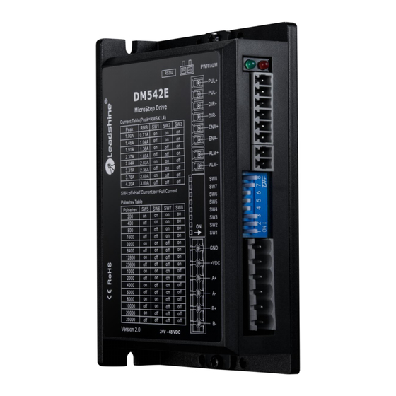
It is recommended to mount the drive vertically to maximize heat sink area. Use forced cooling method to cool if necessary. 3. Connection Pin Assignments and LED Indication Figure 2 Connectors, DIP switches, and LED locations The DM542E has three connector blocks P1&P2&P3 (see above picture). P1 is for control signals connections, and P2 Page | 2... -
Page 6: P1 - Control Connector
DM542E Digital Stepper Drive User Manual is for output signals connections, P3 is for power and motor connections. The following tables are brief descriptions of the three connectors. P4 is for modifying parameters More detailed descriptions are as below. 3.1 P1 - Control Connector... -
Page 7: Led Light Indication
3.5 LED Light Indication There are two LED lights for DM542E. The GREEN one is the power indicator which will be always on generally. The RED one is a protection indicator which will flash 1-2 times in a 3-second period, when protection enabled for a DM542E. -
Page 8: Motor Connection
6. Power Supply Selection The DM542E can power medium and large size stepping motors (frame size from NEMA 11 to 24). To get good driving performances, it is important to select supply voltage and output current properly. Generally speaking, supply voltage determines the high speed performance of the motor, while output current determines the output torque of the driven motor (particularly at lower speed). -
Page 9: Selecting Supply Voltage
7. DIP Switch Configurations The DM542E has one 8-bit DIP switch and one 1-bit selector. The first 8-bit is used to configure settings of micro step resolution, output current, motor standstill current, pulse type and smoothing time as shown below. -
Page 10: Output Current Configurations
The current automatically reduced to 50% of the selected dynamic current 0.4 second after the last pulse. 7.3 Automatic Motor Matching & Self Configuration When powered on a DM542E will automatically configure itself with the best settings to match the driven stepper motor for optimal performance. No action is needed. -
Page 11: Typical Connection
DM542E Digital Stepper Drive User Manual 9. Typical Connection A complete stepping system should include stepping motor, stepping drive, power supply and controller (pulse generator). A typical connection is shown as below. Figure 8 Typical Connections 10. Sequence Chart of Control Signals... -
Page 12: Protection Functions
DM542E Digital Stepper Drive User Manual 11. Protection Functions To improve reliability, the drive incorporates some built-in protections features. Time(s) of Priority Sequence wave of red LED Description Blink Over-current protection activated when peak current exceeds the limit. Over-voltage protection activated when drive working voltage is greater than 60VDC Reserved. -
Page 13: Troubleshooting
DM542E Digital Stepper Drive User Manual 12. Troubleshooting In the event that your drive doesn’t operate properly, the first step is to identify whether the problem is electrical or mechanical in nature. The next step is to isolate the system component that is causing the problem. As part of this process you may have to disconnect the individual components that make up your system and verify that they operate independently. -
Page 14: Warranty
Leadshine Technology Co., Ltd. warrants its products against defects in materials and workmanship for a period of 12 months from shipment out of factory. During the warranty period, Leadshine will either, at its option, repair or replace products which proved to be defective.
Need help?
Do you have a question about the DM542E and is the answer not in the manual?
Questions and answers