
Related Manuals for Leadshine DM805-AI


Summary of Contents for Leadshine DM805-AI
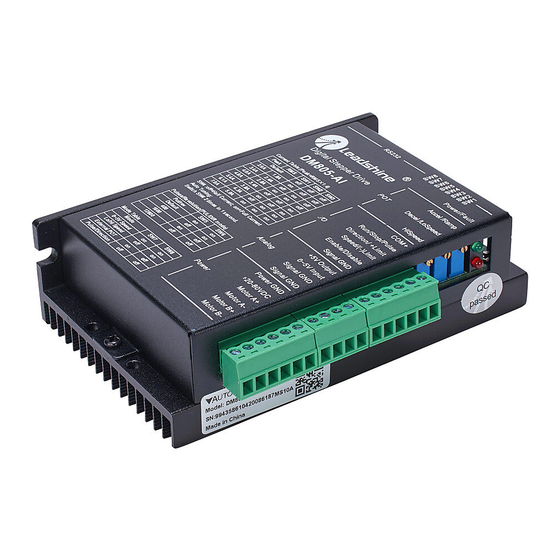
- Page 1 Authorized Distributor of Leadshine Technology Hardware Installation Manual for DM805-AI Digital Stepper Drive with 0‐5V Input www.leadshine.com HWMN‐DMAI‐R20110627 雷赛智能官方代理:雷创智能科技 www.leadtronker.com...
- Page 2 The content in this manual has been carefully prepared and is believed to be accurate, but no responsibility is assumed for inaccuracies. Leadshine reserves the right to make changes without further notice to any products herein to improve reliability, function or design. Leadshine does not assume any liability arising out of the application or use of any product or circuit described herein;...
-
Page 3: Table Of Contents
Authorized Distributor of Leadshine Technology Table of Contents 1. Introduction, Features and Applications........................1 Introduction ................................1 Features ................................... 1 Applications ................................1 2. Specifications ................................2 General Specifications............................. 2 Electrical Specifications ............................2 Input Voltage ..............................2 Pulse Input Frequency ............................. 2 Velocity Control .............................. - Page 4 Authorized Distributor of Leadshine Technology Multiple Drives ..............................13 Selecting Supply Voltage............................13 8. Typical Connection..............................14 Analog 0-5V Speed Mode ............................. 14 Low/High Speed Mode ............................15 External Potentiometer Mode..........................16 Pulse/Direction Mode............................17 9. Wiring Notes ................................18 10.
-
Page 5: Introduction, Features And Applications
Introduction The DM805-AI is a 0-5V input stepper drive with built-in oscillator which is based on the latest digital control algorithm. It brings a unique level of system smoothness, providing optimum torque and nulls mid-range instability. Motor self-test and parameter auto-setup technology offers optimum responses with different motors and easy-to-use. -
Page 6: Specifications
Authorized Distributor of Leadshine Technology DM805-AI Hardware Installation Manual 2. Specifications General Specifications Parameter Typical Unit MΩ Isolation Resistance Logic Signal Current Electrical Specifications Input Voltage Input Voltage Drive Model Typical Unit DM805-AI Pulse Input Frequency Pulse Input Frequency... -
Page 7: Mechanical Specifications
Authorized Distributor of Leadshine Technology DM805-AI Hardware Installation Manual Mechanical Specifications 118 [ 4.646] 112 [ 4.409] 112 [ 4.409] Elimination of Heat Driver’s reliable working temperature should be <70℃(158℉), and motor working temperature should be <80℃(176℉); ... -
Page 8: Connectors And Interface
3. Connectors and Interface The DM805-AI has three connectors, connector for digital I/O signals connections, connector for analog 0-5V signal connections and connector for power and motor connections. The three parameters are used to preset or adjust the speed, acceleration and deceleration ramp. -
Page 9: Operating Mode
Authorized Distributor of Leadshine Technology DM805-AI Hardware Installation Manual 4. Operating Mode The DM805-AI supports four operating modes selected by the DIP switch SW7 and SW8, shown as the following table. Mode Description Analog 0-5V Speed Mode 0~5V Speed... -
Page 10: Ramp Shaping
Authorized Distributor of Leadshine Technology DM805-AI Hardware Installation Manual Ramp Shaping There are two potentiometers Accel and Decel for adjusting the acceleration ramp and deceleration ramp. When the input ramp exceeds the value set by the potentiometer, the actual output ramp will be limited to the potentiometer value. -
Page 11: Ramp Shaping
Authorized Distributor of Leadshine Technology DM805-AI Hardware Installation Manual Ramp Shaping When motor speed switches between low and high or changes direction, the acceleration/deceleration ramp adjusted by the Ramp potentiometer will be inserted automatically for smooth motion. Motor Speed... -
Page 12: Ramp Shaping
Authorized Distributor of Leadshine Technology DM805-AI Hardware Installation Manual Ramp Shaping Motor Speed Actual Speed Command Speed Shaped by the Decel Potentiometer Positive Direction Time Negative Direction Shaped by the Accel Potentiometer Pulse/Direction Mode In this mode motor speed is the proportional to the pulse input frequency and motor rotary angle is controlled by the pulse counts. The microstep can be selected by the DIP switch SW5 and SW6. -
Page 13: Control Signal Requirement
Authorized Distributor of Leadshine Technology DM805-AI Hardware Installation Manual 5. Control Signal Requirement Analog 0-5V Speed Mode High Speed 0-5V Input Low Speed Negative Positive Direction Stop Run/Stop Enable/Disable Remark: Enable Signal Setup Time: Tsr>5us Run Signal Setup Time: Tsr>5us Direction Signal Setup Time: Tsd>5us... -
Page 14: External Potentiometer Mode
Authorized Distributor of Leadshine Technology DM805-AI Hardware Installation Manual External Potentiometer Mode Positive Direction +2.5V Negative Direction 0-5V Input Stop Run/Stop Enable/Disable Remark: Enable Signal Setup Time: Tsr>5us Run Signal Setup Time: Tsr>5us Pulse/Direction Mode Most DM drive can support Pulse/Direction and CW/CCW control signal modes. In order to avoid some fault operations and deviations,... -
Page 15: Connecting The Motor
Authorized Distributor of Leadshine Technology DM805-AI Hardware Installation Manual 6. Connecting the Motor The DM drive can drive any 2-pahse and 4-pahse hybrid stepping motors. 4-lead Motors Connections 4 lead motors are the least flexible but easiest to wire. Speed and torque will depend on winding inductance. In setting the drive output current, multiply the specified phase current by 1.4 to determine the peak output current. -
Page 16: 8-Lead Motors Connections
7. Power Supply Selection The DM drive can match medium and small size stepping motors (from NEMA frame size 14 to 34) made by Leadshine or other motor manufactures around the world. To achieve good driving performances, it is important to select supply voltage and output current properly. -
Page 17: Regulated Or Unregulated Power Supply
Driver Upper Input limit Driver Upper Input limit Driver Upper Input limit Driver Upper Input limit Driver Input Voltage Driver Input Voltage Power Supply Voltage Power Supply Voltage The recommended power supply voltage for DM805-AI is 24-72VDC: HWMN‐DM‐R2011060 雷赛智能官方代理:雷创智能科技 www.leadtronker.com... -
Page 18: Typical Connection
Authorized Distributor of Leadshine Technology DM805-AI Hardware Installation Manual 8. Typical Connection Analog 0-5V Speed Mode Accel/Ramp Accel Decel/LoSpeed Decel HiSpeed HiSpeed COM+ Run/Stop/Pulse Run/Stop Direction/+Limit Direction Speed/(-)Limit Limit Enable/Disable DM805-AI Disable Signal GND +5V Output 0~5V Input 0~5V... -
Page 19: Low/High Speed Mode
Authorized Distributor of Leadshine Technology DM805-AI Hardware Installation Manual Low/High Speed Mode Ramp Accel/Ramp LoSpeed DecelLoSpeed HiSpeed HiSpeed COM+ Run/Stop/Pulse Run/Stop Direction/+Limit Direction Speed/(-)Limit Speed Enable/Disable DM805-AI Disable Signal GND +5V Output 0~5V Input Signal GND Signal GND Power GND... -
Page 20: External Potentiometer Mode
Authorized Distributor of Leadshine Technology DM805-AI Hardware Installation Manual External Potentiometer Mode Accel/Ramp Accel Decel/LoSpeed Decel HiSpeed HiSpeed COM+ Run/Stop/Pulse Run/Stop Direction/+Limit +Limit Speed/(-)Limit -Limit Enable/Disable DM805-AI Disable Signal GND +5V Output 0-2.5V Negative 0~5V Input 2.5-5V Positive Signal GND... -
Page 21: Pulse/Direction Mode
Authorized Distributor of Leadshine Technology DM805-AI Hardware Installation Manual Pulse/Direction Mode A complete stepping system should include stepping motor, stepping drive, power supply and controller (pulse generator). A typical connection of DM856 is shown as follows. COM+ Run/Stop/Pulse Direction/+Limit... -
Page 22: Wiring Notes
10. Configure the Drive The DM805-AI uses an 8-bit DIP switch to set operating mode, microstep resolution and motor operating current as follows. The dynamic current setting by SW1, SW2 and SW3 is active for all operating mode. The microstep resolution setting by SW5 and SW6 only takes effect in Pulse/Direction mode. -
Page 23: Selecting Operating Mode
Authorized Distributor of Leadshine Technology DM805-AI Hardware Installation Manual The user needs to tune the current loop parameter manually. Please refer to the software manual of the DM drive. Auto configuration: Switch SW4 two times in one second. Selecting Operating Mode... -
Page 24: Current Settings
Authorized Distributor of Leadshine Technology DM805-AI Hardware Installation Manual Current Settings Dynamic current setting For a given motor, higher drive current will make the motor to output more torque, but at the same time causes more heating in the motor and drive. -
Page 25: Protection Functions
When power supply voltage exceeds the limit, protection will be activated and RED LED will turn on twice within each periodic time. Negative Limit Protection When the –limit input of the DM805-AI is active, protection will be activated and RED LED will turn three times within each periodic time. The motor will stop immediately without holding torque. -
Page 26: Frequently Asked Questions
Authorized Distributor of Leadshine Technology DM805-AI Hardware Installation Manual 12. Frequently Asked Questions In the event that your drive doesn’t operate properly, the first step is to identify whether the problem is electrical or mechanical in nature. The next step is to isolate the system component that is causing the problem. As part of this process you may have to disconnect the individual components that make up your system and verify that they operate independently. -
Page 27: Appendix
Leadshine Technology Co., Ltd. warrants its products against defects in materials and workmanship for a period of 12 months from shipment out of factory. During the warranty period, Leadshine will either, at its option, repair or replace products which proved to be defective. -
Page 28: Contact Us
Authorized Distributor of Leadshine Technology DM805-AI Hardware Installation Manual CONTACT US China Headquarters Address: 3/F, Block 2, Nanyou Tianan Industrial Park, Nanshan District Shenzhen, China http://www.leadshine.com Web: Sales Hot Line: Tel: 86-755-2641-7674 (for Asia, Australia, Africa areas) 86-755-2640-9254 (for Europe, America areas) Fax: 86-755-2640-2718 Email: sales@leadshine.com.
Need help?
Do you have a question about the DM805-AI and is the answer not in the manual?
Questions and answers