Table of Contents
Advertisement
Quick Links
User Manual
DM542E
2-Phase Digital Stepper Drive
Revision 1.0
©2016 China Leadshine Technology Co., Ltd.
Address: Floor 11, Block A3, Nanshan iPark, Xueyuan Avenue 1001, Shenzhen, Guangdong, 518055, China
Tel: (86)755-26409254
Fax: (86)755-26402718
Web:
www.leadshine.com
Sales:
sales@leadshine.com
Support:
tech@leadshine.com
Advertisement
Table of Contents

Subscribe to Our Youtube Channel
Related Manuals for Leadshine DM542E


Summary of Contents for Leadshine DM542E
- Page 1 User Manual DM542E 2-Phase Digital Stepper Drive Revision 1.0 ©2016 China Leadshine Technology Co., Ltd. Address: Floor 11, Block A3, Nanshan iPark, Xueyuan Avenue 1001, Shenzhen, Guangdong, 518055, China Tel: (86)755-26409254 Fax: (86)755-26402718 Web: www.leadshine.com Sales: sales@leadshine.com Support: tech@leadshine.com...
- Page 2 Strictly adhere to the technical information regarding installation requirements. This manual is not for use or disclosure outside of Leadshine except under permission. All rights are reserved. No part of this manual shall be reproduced, stored in retrieval form, or transmitted by any means, electronic, mechanical, photocopying, recording, or otherwise without approval from Leadshine.
-
Page 3: Table Of Contents
DM542E Digital Stepper Drive User Manual Table of Contents 1. Introductions................................... 1 1.1 Features...................................1 1.2 Applications................................1 2. Specifications...................................1 2.1 Electrical Specifications............................1 2.2 Environment................................2 2.3 Mechanical Specifications............................2 2.4 Elimination of Heat..............................2 3. Connection Pin Assignments and LED Indication...................... 3 3.1 Connector P1 Configurations.......................... -
Page 4: Introductions
Protections for over-voltage and over-current 1.2 Applications The DM542E stepper drive are designed to power 2 phase (1.8°) or 4-phase (0.9°) NEMA 17, 23, and 24 hybrid stepper motors. It can be easily adopted in many industries (CNC, medical, automation, packaging…), such as X-Y tables, engraving machines, labeling machines, mills, plasma, laser cutters, pick and place devices, and so on. -
Page 5: Environment
* Side mounting recommended for better heat dissipation 2.4 Elimination of Heat DM542E reliable working temperature should be < 60℃ (140°F) It is recommended to use automatic idle-current mode to reduce motor heating. That means set the SW4 pin of ... -
Page 6: Connection Pin Assignments And Led Indication
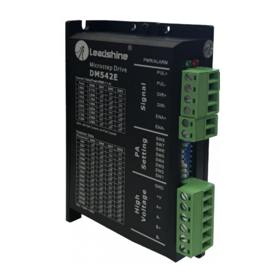
3. Connection Pin Assignments and LED Indication The DM542E has two connector blocks P1&P2 (see above picture). P1 is for control signals connections, and P2 is for power and motor connections. The following tables are brief descriptions of the two connectors. More detailed descriptions of the pins and related issues are presented in section 4, 5, 9. -
Page 7: Led Light Indication
3.3 LED Light Indication There are two LED lights for DM542E. The GREEN one is the power indicator which will be always on generally. The RED one is a protection indicator which will flash 1-2 times in a 3-second period, when protection enabled for a DM542E. -
Page 8: Half Coil Configuration
DM542E Digital Stepper Drive User Manual 5.2.1 Half Coil Configuration As previously stated, the half coil configuration uses 50% of the motor phase windings. This gives lower inductance, hence, lower torque output. Like the parallel connection of 8 lead motor, the torque output will be more stable at higher speeds. -
Page 9: Parallel Connection
6. Power Supply Selection The DM542E can power medium and small size stepping motors (frame size from NEMA17 to 24) made by Leadshine or other motor manufacturers. To get good driving performances, it is important to select supply voltage and output current properly. -
Page 10: Dip Switch Configurations
DM542E Digital Stepper Drive User Manual voltage from the power supply power line voltage fluctuation and back EMF voltage generated during motor deceleration needs also to be taken into account. Ideally it is suggested to use a power supply with the output range of +24 - +48 VDC, leaving room for power line voltage fluctuation and back-EMF. -
Page 11: Dynamic Current Configurations
The current automatically reduced to 50% of the selected dynamic current 0.4 second after the last pulse. 7.3 Automatic Motor Matching & Self Configuration When powered on a DM542E will automatically configure itself with the best settings to match the driven stepper motor for optimal performance. No action is needed. -
Page 12: Typical Connection
DM542E Digital Stepper Drive User Manual 9. Typical Connection A complete stepping system should include stepping motor, stepping drive, power supply and controller (pulse generator). A typical connection is shown as figure 9. Figure 9: Typical connection 10. Sequence Chart of Control Signals... -
Page 13: Protection Functions
DM542E Digital Stepper Drive User Manual 11. Protection Functions To improve reliability, the drive incorporates some built-in protections features. Time(s) of Priority Sequence wave of red LED Description Blink Over-current protection activated when peak current exceeds the limit. Over-voltage protection activated when drive working voltage is greater than 60VDC Reserved. -
Page 14: Troubleshooting
DM542E Digital Stepper Drive User Manual 12. Troubleshooting In the event that your drive doesn’t operate properly, the first step is to identify whether the problem is electrical or mechanical in nature. The next step is to isolate the system component that is causing the problem. As part of this process you may have to disconnect the individual components that make up your system and verify that they operate independently. -
Page 15: Warranty
Leadshine Technology Co., Ltd. warrants its products against defects in materials and workmanship for a period of 12 months from shipment out of factory. During the warranty period, Leadshine will either, at its option, repair or replace products which proved to be defective.
Need help?
Do you have a question about the DM542E and is the answer not in the manual?
Questions and answers