Table of Contents
Advertisement
User's Manual
For
DM2282T
Fully Digital Stepper Drive
Version 1.0
Designed by StepperOnline®
Manufactured by Leadshine®
©2017 All Rights Reserved Attention: Please read this manual
carefully before using the drive!
#7 Zhongke Road, Jiangning, Nanjing, China
T: 0086-2587156578
Web site:
www.omc-stepperonline.com
E-Mail:
sales@stepperonline.com
Advertisement
Table of Contents

Subscribe to Our Youtube Channel
Related Manuals for Leadshine DM2282T


Summary of Contents for Leadshine DM2282T
- Page 1 User’s Manual DM2282T Fully Digital Stepper Drive Version 1.0 Designed by StepperOnline® Manufactured by Leadshine® ©2017 All Rights Reserved Attention: Please read this manual carefully before using the drive! #7 Zhongke Road, Jiangning, Nanjing, China T: 0086-2587156578 Web site: www.omc-stepperonline.com E-Mail: sales@stepperonline.com...
-
Page 2: Table Of Contents
Full Digital Stepper Drive DM2282T Table of Contents 1. Introduction, Features and Applications..........................1 Introduction..................................1 Features....................................1 Applications..................................1 2. Specifications..................................1 Electrical Specifications (Tj = 25℃/77℉)........................1 Operating Environment and other Specifications......................2 Mechanical Specifications (unit: mm [1inch=25.4mm])....................2 Elimination of Heat................................2 3. - Page 3 Full Digital Stepper Drive DM2282T 9. Typical Connection................................8 10. Sequence Chart of Control Signals............................9 11. Protection Functions................................10 12. Frequently Asked Questions.............................. 10 Problem Symptoms and Possible Causes........................10 Web: www.omc-stepperonline.com Tel: 0086-2587156578...
-
Page 4: Introduction, Features And Applications
1. Introduction, Features and Applications Introduction The DM2282T is a fully digital stepper drive developed with advanced DSP control algorithm based on the latest motion control technology. It has achieved a unique level of system smoothness, providing optimal torque and nulls mid-range instability. -
Page 5: Operating Environment And Other Specifications
Full Digital Stepper Drive DM2282T Operating Environment and other Specifications Cooling Natural Cooling or Forced cooling Environment Avoid dust, oil fog and corrosive gases 0℃ - 50℃ Ambient Temperature Operating Environment Humidity 40%RH - 90%RH 45℃ Max Operating Temperature 10-55Hz/0.15mm... -
Page 6: Pin Assignment And Description
Full Digital Stepper Drive DM2282T 3. Pin Assignment and Description The DM2282T has two connectors, connector P1 for control signals connections, and connector P2 for power and motor connections. The following tables are brief descriptions of the two connectors. More detailed descriptions of the pins and related issues are presented in section 4, 5, 9. -
Page 7: Rs232 Communication Port
The DM2282T can accept differential and single-ended inputs (including open-collector and PNP output). The DM2282T has 3 optically isolated logic inputs which are located on connector P1 to accept line drive control signals. These inputs are isolated to minimize or eliminate electrical noises coupled onto the drive control signals. -
Page 8: Connecting The Motor
(common-anode) 5. Connecting the Motor The DM2282T can drive any 2-pahse and 4-pahse hybrid stepping motors. Connections to 4-lead Motors 4 lead motors are the least flexible but easiest to wire. Speed and torque will depend on winding inductance. In setting the drive output current, multiply the specified phase current by 1.4 to determine the peak output current. -
Page 9: Connections To 8-Lead Motors
6. Power Supply Selection The power supply voltage can work normally between the voltage range specified by the driver. The DM2282T is directly powered by AC. It is recommended that the user use the highest voltage lower than the driver's specified voltage to avoid the grid fluctuation exceeding the driver voltage operating range. -
Page 10: Selecting Microstep Resolution And Drive Output Current
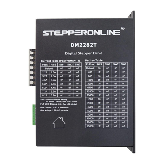
Full Digital Stepper Drive DM2282T 7. Selecting Microstep Resolution and Drive Output Current This drive uses an 8-bit DIP switch to set microstep resolution, and motor operating current, as shown below: Microstep Resolution Selection Microstep resolution is set by SW5, 6, 7, 8 of the DIP switch as shown in the following table: Microstep Steps/rev.(for 1.8°motor) -
Page 11: Dynamic Current Setting
Full Digital Stepper Drive DM2282T Dynamic Current Setting Peak Current RMS Current Default Default 2.2A 1.6A 3.2A 2.3A 4.2A 3.2A 5.2A 3.7A 6.3A 4.4A 7.2A 5.2A 8.2A 5.9A Notes: Due to motor inductance, the actual current in the coil may be smaller than the dynamic current setting, particularly under high speed condition. -
Page 12: Sequence Chart Of Control Signals
Full Digital Stepper Drive DM2282T Figure 10: Typical connection 10. Sequence Chart of Control Signals In order to avoid some fault operations and deviations, PUL, DIR and ENA should abide by some rules, shown as following diagram: Figure 11: Sequence chart of control signals Remark : a)t1: ENA must be ahead of DIR by at least 5s. -
Page 13: Protection Functions
Full Digital Stepper Drive DM2282T c)t3: Pulse width not less than 2.5s; d)t4: Low level width not less than 2.5s. 11. Protection Functions To improve reliability, the drive incorporates some built-in protections features. Time(s) of Priority Sequence wave of RED LED... - Page 14 Full Digital Stepper Drive DM2282T DIP switch current setting is wrong Fault condition exists The drive is disabled Motor phases may be connected in reverse DIP switch current setting is wrong Something wrong with motor coil Control signal is too weak...
Need help?
Do you have a question about the DM2282T and is the answer not in the manual?
Questions and answers