Sign In
Upload
Download
Table of Contents
Contents
Add to my manuals
Delete from my manuals
Share
URL of this page:
HTML Link:
Bookmark this page
Add
Manual will be automatically added to "My Manuals"
Print this page
×
Bookmark added
×
Added to my manuals
Manuals
Brands
Leadshine Manuals
DC Drives
DM Series
Hardware installation manual
Leadshine DM Series Hardware Installation Manual
Fully digital stepper drives
Hide thumbs
1
2
3
Table Of Contents
4
5
6
7
8
9
10
11
12
13
14
15
16
17
18
19
20
21
page
of
21
Go
/
21
Contents
Table of Contents
Bookmarks
Table of Contents
Table of Contents
Family Overview
Introduction
Product Covered
Low Voltage DM Stepper Drives
High Voltage DM Stepper Drives
Mechanical Specifications
Elimination of Heat
Connectors and Pin Assignment
Control Signal Requirement
Signal Mode and Sequence Chart
Connections to Control Signal
Single-Ended Open-Collector Signal Connections
Single-Ended PNP Signal Connections
Differential Signal Connections
Connecting the Motor
4-Lead Motors Connections
6-Lead Motors Connections
Half Coil Configurations
Full Coil Configurations
Series Connections
Parallel Connections
Matching Stepper Motors
Power Supply Selection
Regulated or Unregulated Power Supply
Multiple Drives
Selecting Supply Voltage
Recommended Supply Voltage
Typical Connection
Wiring Notes
Configure the Drive
Auto Tuning by SW4
Microstep Resolution Selection
Current Settings
Dynamic Current Setting
Idle Current Setting
Protection Functions
Over-Current Protection
Over-Voltage Protection
Phase Error Protection
Protection Indications
Frequently Asked Questions
Problem Symptoms and Possible Causes
Appendix
Twelve Month Limited Warranty
Exclusions
Obtaining Warranty Service
Warranty Limitations
Shipping Failed Product
Contact Us
Advertisement
Quick Links
1
Table of Contents
Download this manual
Hardware Installation Manual for
Fully Digital Stepper Drives
www.leadshine.com
HWMN‐DM‐R20110603
Table of
Contents
Previous
Page
Next
Page
1
2
3
4
5
Advertisement
Table of Contents
Need help?
Do you have a question about the DM Series and is the answer not in the manual?
Ask a question
Questions and answers
Related Manuals for Leadshine DM Series
DC Drives Leadshine DM1182 User Manual
2-phase digital stepper drive (21 pages)
Control Unit Leadshine DM856 User Manual
Fully digital stepping driver (16 pages)
Control Unit Leadshine DM556 User Manual
(16 pages)
Control Unit Leadshine DM2282 User Manual
2-phase digital stepper drive (7 pages)
DC Drives Leadshine STEPPERONLINE DM320T User Manual
2-phase digital stepper driver (13 pages)
DC Drives Leadshine DM805-AI Hardware Installation Manual
Digital stepper drive with 0-5v input (28 pages)
DC Drives Leadshine DM2282T User Manual
Fully digital stepper drive (14 pages)
DC Drives Leadshine DM860E User Manual
2-phase digital stepper drive (15 pages)
DC Drives Leadshine DM556E User Manual
2-phase digital stepper drive (15 pages)
DC Drives Leadshine DM556E User Manual
2-phase digital stepper drive (14 pages)
DC Drives Leadshine DMA882S User Manual
2-phase digital stepper drive (16 pages)
DC Drives Leadshine DM860 User Manual
(13 pages)
DC Drives Leadshine DM542E User Manual
2-phase digital stepper drive (14 pages)
DC Drives Leadshine DMA860E User Manual
2-phase digital stepper drive (15 pages)
DC Drives Leadshine DM432C Hardware Installation Manual
Fully digital stepper drives (21 pages)
DC Drives Leadshine DMA860H User Manual
Fully digital stepper drive (16 pages)
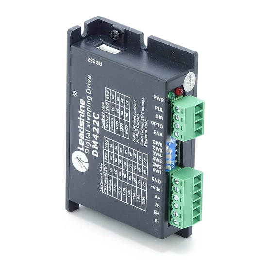
This manual is also suitable for:
Dm320c
Dm422c
Dm422
Dm432c
Dm442
Dm556
...
Show all
Dm856
Dm870
Dm1182
Dm2282
Table of Contents
Print
Rename the bookmark
Delete bookmark?
Delete from my manuals?
Login
Sign In
OR
Sign in with Facebook
Sign in with Google
Upload manual
Upload from disk
Upload from URL


Need help?
Do you have a question about the DM Series and is the answer not in the manual?
Questions and answers