Table of Contents
Advertisement
Quick Links
User Manual
DM556T
2-Phase Digital Stepper Drive
Designed by StepperOnline®
Manufactured by Leadshine®
©2017 All Rights Reserved
Address: #7 Zhongke Road, Jiangning, Nanjing, China
Tel: 0086-2587156578
Web: www.omc-stepperonline.com
Sales: sales@stepperonline.com
Support: technical@stepperonline.com
Advertisement
Table of Contents

Related Manuals for Leadshine DM556T


Summary of Contents for Leadshine DM556T
- Page 1 User Manual DM556T 2-Phase Digital Stepper Drive Designed by StepperOnline® Manufactured by Leadshine® ©2017 All Rights Reserved Address: #7 Zhongke Road, Jiangning, Nanjing, China Tel: 0086-2587156578 Web: www.omc-stepperonline.com Sales: sales@stepperonline.com Support: technical@stepperonline.com...
-
Page 2: Table Of Contents
Digital Stepper Drive DM556T Table of Contents 1. Introductions................................... 1 1.1 Features...................................1 1.2 Applications................................1 2. Specifications...................................1 2.1 Electrical Specifications............................1 2.2 Environment................................2 2.3 Mechanical Specifications............................2 2.4 Elimination of Heat..............................2 3. Connection Pin Assignments and LED Indication...................... 3 3.1 Connector P1 Configurations..........................3 3.2 Connector P2 Configurations.......................... -
Page 3: Introductions
Protections for over-voltage and over-current 1.2 Applications The DM556T stepper drive are designed to power 2 phase (1.8°) or 4-phase (0.9°) NEMA 23, 24, and 34 hybrid stepper motors. It can be easily adopted in many industries (CNC, medical, automation, packaging…), such as X-Y tables, engraving machines, labeling machines, mills, plasma, laser cutters, pick and place devices, and so on. -
Page 4: Environment
* Side mounting recommended for better heat dissipation 2.4 Elimination of Heat DM556T reliable working temperature should be < 60℃ (140°F) It is recommended to use automatic idle-current mode to reduce motor heating. That means set the SW4 pin of ... -
Page 5: Connection Pin Assignments And Led Indication
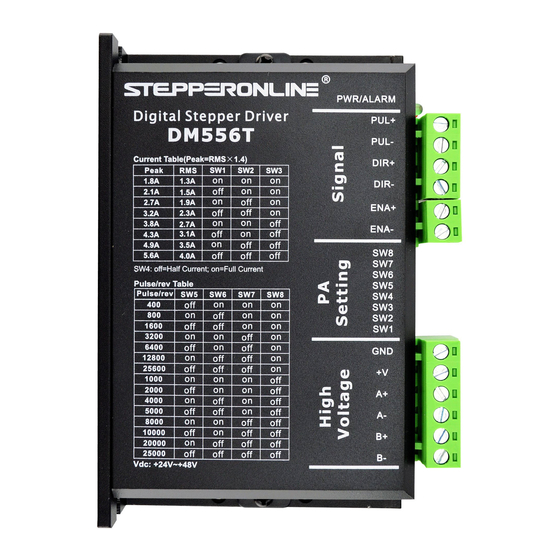
3. Connection Pin Assignments and LED Indication The DM556T has two connector blocks P1&P2 (see above picture). P1 is for control signals connections, and P2 is for power and motor connections. The following tables are brief descriptions of the two connectors. More detailed descriptions of the pins and related issues are presented in section 4, 5, 9. -
Page 6: Led Light Indication
3.3 LED Light Indication There are two LED lights for DM556T. The GREEN one is the power indicator which will be always on generally. The RED one is a protection indicator which will flash 1-2 times in a 3-second period, when protection enabled for a DM556T. -
Page 7: Half Coil Configuration
Digital Stepper Drive DM556T 5.2.1 Half Coil Configuration As previously stated, the half coil configuration uses 50% of the motor phase windings. This gives lower inductance, hence, lower torque output. Like the parallel connection of 8 lead motor, the torque output will be more stable at higher speeds. -
Page 8: Parallel Connection
Figure 8: 8-lead motor parallel connections 6. Power Supply Selection The DM556T can power medium and small size stepping motors (frame size from NEMA23 to 34). To get good driving performances, it is important to select supply voltage and output current properly. Generally speaking, supply voltage determines the high speed performance of the motor, while output current determines the output torque of the driven motor (particularly at lower speed). -
Page 9: Dip Switch Configurations
Digital Stepper Drive DM556T +24 - +48 VDC, leaving room for power line voltage fluctuation and back-EMF. Higher supply voltage can increase motor torque at higher speeds, thus helpful for avoiding losing steps. However, higher voltage may cause bigger motor vibration at lower speed, and it may also cause over-voltage protection or even drive damage. -
Page 10: Dynamic Current Configurations
The current automatically reduced to 50% of the selected dynamic current 0.4 second after the last pulse. 7.3 Automatic Motor Matching & Self Configuration When powered on a DM556T will automatically configure itself with the best settings to match the driven stepper motor for optimal performance. No action is needed. -
Page 11: Sequence Chart Of Control Signals
Digital Stepper Drive DM556T Figure 9: Typical connection 10. Sequence Chart of Control Signals In order to avoid some fault operations and deviations, PUL, DIR and ENA should abide by some rules, shown as following diagram: Figure 10: Sequence chart of control signals Remark: t1: ENA must be ahead of DIR by at least 5s. -
Page 12: Troubleshooting
Digital Stepper Drive DM556T Time(s) of Priority Sequence wave of red LED Description Blink Over-current protection activated when peak current exceeds the limit. Over-voltage protection activated when drive working voltage is greater than 60VDC Reserved. When above protections are active, the motor shaft will be free or the red LED blinks. Reset the drive by repowering it to make it function properly after removing above problems. -
Page 13: Warranty
Digital Stepper Drive DM556T Acceleration is set too high Power supply voltage too low Inadequate heat sinking / cooling Excessive motor and drive heating Automatic current reduction function not being utilized Current is set too high 13. Warranty Twelve Month Warranty StepperOnline warrants its products against defects in materials and workmanship for a period of 12 months from shipment.
Need help?
Do you have a question about the DM556T and is the answer not in the manual?
Questions and answers