Table of Contents
Advertisement
Quick Links
User Manual
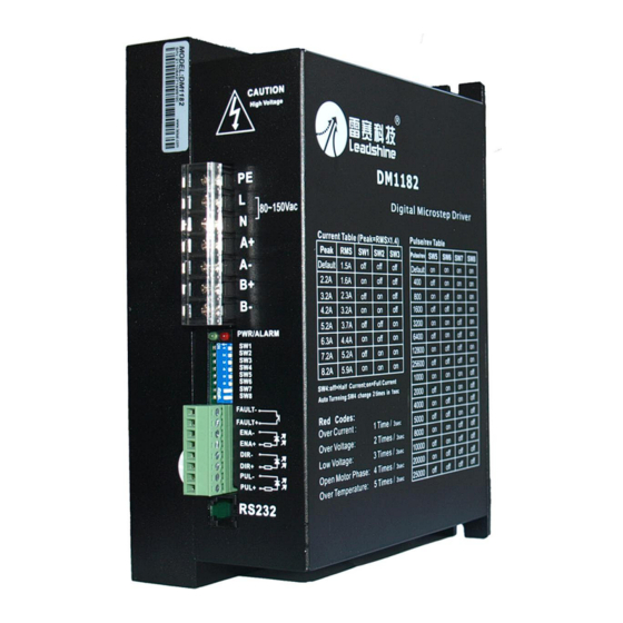
DM1182
2-Phase Digital Stepper Drive
©2012 China Leadshine Technology Co., Ltd.
Address: 15-20/F, Block B, Nanshan I Valley, No.3185, Shahe West Road,
Nanshan District, Shenzhen, Guangdong, 518055, China
Tel: (86)755-26409254
Fax: (86)755-26402718
Web:
Sales:
www.leadshine.com
sales@leadshine.com
Support:
tech@leadshine.com
Advertisement
Table of Contents

Related Manuals for Leadshine DM1182


Summary of Contents for Leadshine DM1182
- Page 1 User Manual DM1182 2-Phase Digital Stepper Drive ©2012 China Leadshine Technology Co., Ltd. Address: 15-20/F, Block B, Nanshan I Valley, No.3185, Shahe West Road, Nanshan District, Shenzhen, Guangdong, 518055, China Tel: (86)755-26409254 Fax: (86)755-26402718 Web: Sales: www.leadshine.com sales@leadshine.com Support: tech@leadshine.com...
-
Page 2: Table Of Contents
Contents Table of Contents 1. Introduction, Features and Applications..............1 1.1 Introduction....................... 1 1.2 Features......................1 1.3 Applications.......................1 2. Specifications.......................2 2.1 Electrical Specifications..................2 2.2 Mechanical Specifications.................2 2.3 Elimination of Heat................... 2 2.4 Operating Environment and other Specifications..........3 3. Pin Assignment and Description................. 3 3.1 Connector P1 Configurations................ - Page 3 Contents 8.3 Configure Stand-still current................10 9. Wiring Notes......................11 10. Typical Connection....................11 11. Sequence Chart of Control Signals................. 12 12. Protection Functions....................12 12.1 Over-current Protection................12 12.2 Over-voltage Protection................13 12.3 Under-voltage Protection................13 12.4 Phase Error Protection.................. 13 12.5 Over temperature Protection.................13 12.6 Protection Indications...................
-
Page 4: Introduction, Features And Applications
Soft-start with no “jump” when powered on 1.3 Applications DM1182 can drive a wide range of 2-phase stepper motors, from NEMA size 34 to 51. It can be implemented in various OEM applications such as laser cutters, laser markers, high precision X-Y tables, labeling machines, CNC router, CNC milling, etc. -
Page 5: Specifications
<80˚C (176℉); It is recommended to use automatic idle-current mode, which automatically reduces motor stand-still current to 60%, thus to reduce heating of DM1182 and the driven stepper motor; Use forced cooling method to cool the system if necessary. ... -
Page 6: Operating Environment And Other Specifications
DM1182 can accept differential and single-ended input signals (including open-collector and PNP output). DM1182 has two connectors, connector P1 for control signals connections, and connector P2 for power and motor connections. The following tables are brief descriptions for the two connectors. -
Page 7: Selecting Active Pulse Edge And Control Signal Mode
DM1182 can accept differential and single-ended inputs (including open-collector and PNP output). DM1182 has 3 optically isolated logic inputs which are located on connector P1 to accept line driver control signals. These inputs are isolated to minimize or eliminate electrical noises coupled onto the drive control signals. -
Page 8: Connecting The Motor
Figure 3: Connection to PNP signal (common-cathode) 5. Connecting the Motor DM1182 can drive any 2-pahse and 4-pahse hybrid stepper motors. 5.1 Connections to 4-lead Motors 4 lead motors are the least flexible but easiest to wire. Speed and torque will depend on winding inductance. -
Page 9: Connections To 6-Lead Motors
DM1182 Digital Stepper Drive Manual V1.1 5.2 Connections to 6-lead Motors Like 8 lead stepper motors, 6 lead motors have two configurations available for high speed or high torque operation. The higher speed configuration, or half coil, is so described because it uses one half of the motor’s inductor windings. -
Page 10: Parallel Connections
7. Power Supply Selection DM1182 can match large and medium size stepper motors (from NEMA size 34 to 51) made by Leadshine or other motor manufactures around the world. To achieve good driving performances, it is important to select supply voltage and output current properly. -
Page 11: Selecting Supply Voltage
And the power of the isolation transformer should larger than 500 watts. Selecting Supply Voltage Working input voltage range of DM1182 is 80 to 150VAC or 113 to 212VDC. That should also count power input fluctuation and back EMF voltage generated by motor coils during motor shaft deceleration. -
Page 12: Configure Output Current
10000 20000 25000 8.2 Configure Output Current Output current of DM1182 is configured via DIP Switch 1, 2, and 3 (See figure 9). DM1182 output current settings are shown in the following table: Peak Current RMS Current Default/Software configured (0.5 to 8.2A) 2.2A... -
Page 13: Soft-Start
DM1182 output RMS current setting closest to the rated phase current of the stepper motor. Higher output current from DM1182 will result higher torque from the driven motor; but at the same time, it also results more heating in both the motor and drive. Therefore, a user is recommended to set output current to a value which will provide enough torque for an application, but not overheat the drive &... -
Page 14: Wiring Notes
Otherwise, the disturbing signals generated by motor could disturb pulse direction signals, causing motor position error, system instability and other failures. When sharing a single power supply among multiple DM1182 stepper drives, separately connecting those stepper drives is recommended instead of daisy-chaining. -
Page 15: Sequence Chart Of Control Signals
Figure 10: Sequence chart of control signals Remark: t1: ENA must be ahead of DIR by at least 100ms due to soft-start feature of DM1182. Usually, ENA+ and ENA- are NC (not connected). See “Connector P1 Configurations” for more information. -
Page 16: Over-Voltage Protection
When above protections are active, the motor shaft will be free or the red LED will be turned on. Reset DM1182 to make it function properly by repowering and removing a protection or protections. Since there is no protection against power leads (﹢, ﹣) reversal, it is critical to make sure that power supply leads are correctly connected to driver. -
Page 17: Frequently Asked Questions
DM1182 Digital Stepper Drive Manual V1.1 13. Frequently Asked Questions In the event that a DM1182 stepper drive doesn’t work properly, the first step is to identify whether the problem is electrical or mechanical in nature. Next, a user should isolate the control system components with a problem. -
Page 18: Problem Symptoms And Possible Causes
DM1182 Digital Stepper Drive Manual V1.1 Problem Symptoms and Possible Causes Symptoms Possible Problems No power Microstep resolution setting is wrong Motor is not rotating DIP switch current setting is wrong Fault condition exists The driver is disabled Motor rotates in the wrong direction... -
Page 19: Appendix
Twelve Month Limited Warranty Leadshine Technology Co., Ltd. generally offers 12-month (except special cases) warranty for defects of materials and workmanship, from the delivered date. During the warranty period, Leadshine will either, at its option, repair or replace products proved to be defective. - Page 20 DM1182 Digital Stepper Drive Manual V1.1 Send to the following address for North America clients only Leadshine America, Inc. 25 Mauchly, Suite 318 Irvine, CA 92618 Leadshine headquarters Leadshine Technology Co. Ltd. 3/F, Block 2 Nanyou Tianan Industrial Park...
-
Page 21: Contact Us
DM1182 Microstepping29 Driver Manual V1.1 Contact Us China Headquarters Address: 3/F, Block 2, Nanyou Tianan Industrial Park, Nanshan District Shenzhen, China Web: http://www.leadshine.com Sales Hot Line: Tel: 86-755-2641-7674 (for Asia, Australia, Africa areas) 86-755-2640-9254 (for Europe areas) 86-755-2641-7617 (for America areas) Fax: 86-755-2640-2718 Email: sales@leadshine.com.
Need help?
Do you have a question about the DM1182 and is the answer not in the manual?
Questions and answers