Table of Contents
Advertisement
Quick Links
NetSure 531 AC1 Power Supply System
User Manual
Version
Revision date
BOM
Vertiv Tech provides customers with technical support. Users may contact the nearest
Vertiv local sales office or service center.
Copyright © 2017 by Vertiv Tech Co., Ltd.
All rights reserved. The contents in this document are subject to change without notice.
Vertiv Tech Co., Ltd.
Address: Block B2, Nanshan I Park, No.1001 Xueyuan Road, Nanshan District, Shenzhen,
518055, P.R.China
Homepage: www.vertivco.com
E-mail: overseas.support@vertivco.com
V1.2
December 30, 2017
31013070
Advertisement
Table of Contents

Related Manuals for Vertiv NetSure 531 AC1


Summary of Contents for Vertiv NetSure 531 AC1
- Page 1 Revision date December 30, 2017 31013070 Vertiv Tech provides customers with technical support. Users may contact the nearest Vertiv local sales office or service center. Copyright © 2017 by Vertiv Tech Co., Ltd. All rights reserved. The contents in this document are subject to change without notice.
- Page 3 When operating Vertiv products, the operation personnel must observe the safety rules in the industry, the general safety points and special safety instructions specified in this book.
- Page 4 IV. ESD Note The static electricity generated by the human body will damage the static sensitive elements on PCBs, such as large-scale ICs. Before touching any plug-in board, PCB or IC chip, you should wear the ESD wrist strap to prevent body static from damaging the sensitive components.
- Page 5 BLVD The power supply system has load low voltage disconnection (LLVD) function and battery low voltage disconnection (BLVD) function. LLVD means when the mains fails and batteries supply power, the power supply system cuts the non-priority load off when the battery voltage drops down to 44V. In this way, the battery remaining capacity can sustain the priority load longer.
- Page 6 III. Power cable Note Please verify the cable labels before connection. IV. Signal cables Note The signal cables should be routed at least 150mm away from power cables.
-
Page 7: Table Of Contents
Contents Chapter 1 Overview ................................1 1.1 Model Description ..............................1 1.2 Composition & Configuration ..........................1 1.3 Options ................................. 2 1.4 Features ................................3 Chapter 2 Installation Instruction ............................4 2.1 Safety Regulations ..............................4 2.2 Preparation ................................4 2.3 Mechanical Installation ............................ - Page 8 4.7.2 Battery Settings ............................27 4.7.3 AC Settings .............................. 31 4.7.4 DC Settings ............................. 32 4.7.5 Rectifier Settings ............................. 32 4.7.6 System Settings ............................33 4.7.7 Communication Settings .......................... 34 4.8 Setting Energy Saving ............................34 4.9 Fast Settings ............................... 35 Chapter 5 Rectifier ................................
-
Page 9: Chapter 1 Overview
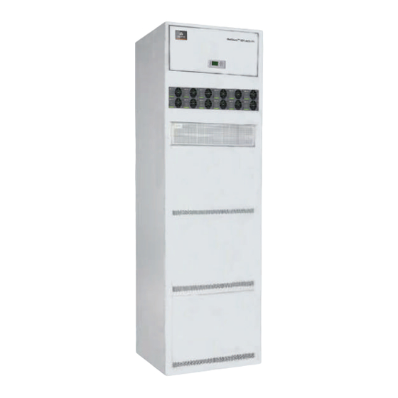
NetSure 531 AC1-Y6 power supply systems are integrated, fixed-configuration cabinets with battery compartments; NetSure 531 AC1-W6 power supply system is a fixed-configuration cabinet without battery compartment. The appearances of the NetSure 531 AC1 power supply system are shown in Figure 1-2, Figure 1-3 and Figure 1-4. LLVD MCB... -
Page 10: Options
Battery MCB Rectifier Figure 1-4 Appearance of NetSure 531 AC1-W6 power supply system The configuration of the NetSure 531 AC1 power supply system is listed in Table 1-1. Table 1-1 Configuration of the NetSure 531 AC1 power supply system Description... -
Page 11: Features
The power supply system has perfect lightning protection at both AC side and DC side The power supply system has complete fault protection and fault alarm functions NetSure 531 AC1 Power Supply System User Manual... -
Page 12: Chapter 2 Installation Instruction
The equipment should be unpacked and inspected after it arrives at the installation site. The inspection shall be done by representatives of both the user and Vertiv Tech Co., Ltd. To inspect the equipment, you should open the packing case, take out the packing list and check against the packing list that the equipment is correct and complete. -
Page 13: Mechanical Installation
Front Cabinet 600mm ≥800mm 600mm Figure 2-1 Equipment room layout Note If the system fixed on a battery cabinet is installed against the wall, the installation sequence should be as follows: NetSure 531 AC1 Power Supply System User Manual... - Page 14 Figure 2-3 Installing the power supply system to the battery cabinet (back view) 2. Use the fixing bolts to fix the power supply system to the battery cabinet, as shown in Figure 2-4. NetSure 531 AC1 Power Supply System User Manual...
- Page 15 Figure 2-5 and Figure 2-6. Bolt Installation assembly A amplified Figure 2-5 Installing the power supply system to the wall (a) Bolt Bolt Installation assembly Figure 2-6 Installing the power supply system to the wall (b) NetSure 531 AC1 Power Supply System User Manual...
-
Page 16: Installing Rectifiers
Connect one end of the earth cable to the earth busbar of the machine room, and the other end to the earth terminal of the power supply system. Feed the cables into the cabinet from the top. The position of the earth terminal is shown in Figure 2-9. NetSure 531 AC1 Power Supply System User Manual... - Page 17 Connect the negative load cable to the upper terminal of load MCBs (LLVD MCBs and BLVD MCBs). Connect the positive load cable to the DC positive busbar, as shown in Figure 2-11. NetSure 531 AC1 Power Supply System User Manual...
- Page 18 Bind the cables beside the battery. Wrap all the bare parts of the cable terminals with insulating tape. Do not connect the cables to the battery until the DC distribution unit is to be tested. The positions of the battery cable entry holes are shown in Figure 2-12. NetSure 531 AC1 Power Supply System User Manual...
-
Page 19: Connecting Signal Cables
J433 J404 J403 J402 J420 J417 J418 J430 J421 Figure 2-14 Interfaces of the controller The functions of the interfaces are given in Table 2-4. Connect signal cables according to Table 2-4. NetSure 531 AC1 Power Supply System User Manual... - Page 20 J403_2/ J404_2 (DO6) Reserved J402_1/ J403_1 (DO3) Rectifier failure J404_1 (DO7) Reserved J402_2/ J403_2 (DO4) BLVD J404_2 (DO8) Reserved Note: The above functions are default settings. You can change them through the controller NetSure 531 AC1 Power Supply System User Manual...
-
Page 21: Chapter 3 Testing
±0.3V Start and stop each rectifier of the system by inserting and unplugging the rectifier. Check their output voltages of the rectifiers NetSure 531 AC1 Power Supply System User Manual... -
Page 22: Basic Settings
There should be no alarms during normal system operation. The system operation status check can be conducted through the controller. For the parameter query method, refer to 4.3 Querying System Main Information and 4.4 Querying Rectifier Status. NetSure 531 AC1 Power Supply System User Manual... -
Page 23: Final Steps
If any defect is found in this equipment, inform the personnel responsible for the contract. If repairing is needed, please fill in the FAILURE REPORT and send the report together with the defective unit to the repairing center for fault analysis. NetSure 531 AC1 Power Supply System User Manual... -
Page 24: Chapter 4 Use Of The Controller
When the controller is powered on, the language selection page will appear and the controller will be initialized. The default language is English. After initialization, the first page of system information will appear. NetSure 531 AC1 Power Supply System User Manual... -
Page 25: Enter Password Page
Figure 4-4. MAINMENU Energy Saving Status Fast settings Settings Maintenance Figure 4-4 MAINMENU page 1. At any system information page, press ENT to enter the MAINMENU page. NetSure 531 AC1 Power Supply System User Manual... -
Page 26: Status Page
You can enter the Maintenance page after you input the correct password. For this menu, the user, engineer and administrator have the same authorities. The Maintenance page is shown in Figure 4-7. NetSure 531 AC1 Power Supply System User Manual... -
Page 27: Energy Saving Page
ESC repeatedly to return to the first system information page. DC voltage and current, system operation state, battery state and battery management mode are displayed in the first system information page, as shown in Figure 4-10. NetSure 531 AC1 Power Supply System User Manual... - Page 28 At the Sys Used page, press ▼ to enter the system temperature information page. If a temperature sensor is configured, the system will display a page on Bat. Temp and Amb. Temp, as shown in Figure 4-14. NetSure 531 AC1 Power Supply System User Manual...
-
Page 29: Querying Rectifier Status
The preceding page includes alarm serial No., alarm name, alarm level and time. The alarm raising time determines the sequence it is displayed, with the latest alarm displayed first. Use ▲ or ▼ to view all active alarms. NetSure 531 AC1 Power Supply System User Manual... - Page 30 Aux Load Fails Batt Fuse Alarm 1 Batt Fuse Alarm 2 Batt Fuse Alarm 3 Batt Fuse Alarm 4 Batt 1 Curr High Non Float Status Battery Batt Discharge management Load share Alarm NetSure 531 AC1 Power Supply System User Manual...
-
Page 31: Querying History Alarm
Finally, after the battery test, the battery management mode will be changed from Manual to Auto automatically. 2) Battery: The options include Reconnect and Disconnect. If there is a battery alarm, the battery operations will be invalid. NetSure 531 AC1 Power Supply System User Manual... -
Page 32: Setting
Critical alarm, major alarm: These two types of alarms have strong impacts on the system performance. Whenever these alarms are generated, you are supposed to handle them immediately. The alarm indicators will be on and audible indication will be given. NetSure 531 AC1 Power Supply System User Manual... - Page 33 Temp 90° Rect Failure The rectifier voltage is higher than upper limit voltage Major Rect Protect Rectifier performs self- protection and has no output Observation Rect Fan Fails Rectifier fan fails Critical NetSure 531 AC1 Power Supply System User Manual...
- Page 34 Press ▲ or ▼ to modify the number and letter of DI name on the third line after pressing the ENT to confirm, press ◄ or ► to move the cursor left or right and input ‘#’ to end. Finally, press ENT to confirm. The value description of the parameter is listed in Table 4-6. NetSure 531 AC1 Power Supply System User Manual...
-
Page 35: Battery Settings
NetSure 531 AC1-Y1: Shunt Coeff 300A; NetSure 531 You can set shunt parameters when ‘System Type’ is ‘SET’ 1A ~ 5000A Current AC1-Y6, NetSure 531 AC1-W6: 150A Shunt Coeff 1mV ~ 500mV 25mV Volt NetSure 531 AC1 Power Supply System User Manual... - Page 36 0.25C rated capacity of one battery string Over (over current 0.3C If the battery charging current is higher than the Over, it will raise the 0.3C point) 1.0C battery charge over-current alarm NetSure 531 AC1 Power Supply System User Manual...
- Page 37 Cyc Test Time: -Enable: No Stable Test 07-01-00:00 -Time: 300min 01-01-00:00 -Alarm: -Enable: No 10-01-00:00 -Cap: 0.70C 04-01-00:00 -Period: 720h -Current: 9999A Figure 4-28 Battery test settings page NetSure 531 AC1 Power Supply System User Manual...
- Page 38 Figure 4-29 Schematic diagram of the test function Temperature coefficient 1. At the BAT Settings page, press ▲ or ▼ to select Temp. Comp menu. Then press ENT to confirm. There are two pages, as shown in Figure 4-30. NetSure 531 AC1 Power Supply System User Manual...
-
Page 39: Ac Settings
‘No’ if the AC sampling board is not configured Manual Setting according to the actual configuration. Choose ‘1-PH’ and ‘3-PH’ if AC PH 1-PH, 3-PH 3-PH the AC sampling board is configured NetSure 531 AC1 Power Supply System User Manual... -
Page 40: Dc Settings
The rectifier over voltage alarm will be raised when the rectifier output HVSD 56V ~ 59V voltage is higher than the HVSD voltage Default output voltage when communication interrupted. Must be lower than Default V 48V ~ 58V 53.5V this value NetSure 531 AC1 Power Supply System User Manual... -
Page 41: System Settings
48V/1000 and equipment configured with system 48V/SET ComDownLoad Y, N Reset PWD Y, N Whether resetting the password to the default Reset Para Y, N Whether resetting the parameters to the default NetSure 531 AC1 Power Supply System User Manual... -
Page 42: Communication Settings
If the battery current and load current change, the controller will switch off some power-on rectifiers or switch on some power-off rectifiers. In any case, the system guarantees at least one rectifier to work. 2. Prerequisite NetSure 531 AC1 Power Supply System User Manual... -
Page 43: Fast Settings
48V/1000 48V/SET The capacity of the total battery strings. You should set this parameter Capacity 50Ah ~ 5000Ah 300Ah according to the actual battery configuration NetSure 531 AC1 Power Supply System User Manual... -
Page 44: Chapter 5 Rectifier
Figure 5-3. The functions of the pins are listed in Table 5-2. J1 J7 J15 J25 J12 J22 J14 J24 J8 J16 J26 Figure 5-3 Rear panel of the rectifier NetSure 531 AC1 Power Supply System User Manual... -
Page 45: Functions & Features
The software over-voltage protection point can be set by the controller, the setting range is 56V ~ 59V, which must be at least 0.5Vdc higher than the output voltage. The factory default setting is 59V. NetSure 531 AC1 Power Supply System User Manual... - Page 46 (red) turns off. If the serious imbalanced current is generated, and the system average load current is bigger than the 10% of the rated current (the rated current is 30A), the fault indicator (red) turns on. NetSure 531 AC1 Power Supply System User Manual...
-
Page 47: Technical Parameters
Input voltage fluctuation and Reference standard: EN61000-3-3 flash Class A (DC side) Reference standard: EN300386:2012 Conducted emission Class A (DC side) Reference standard: EN55022 Class A (AC side) Reference standard: EN55022 Radiated emission Class A NetSure 531 AC1 Power Supply System User Manual... - Page 48 DC output terminal to enclosure: 707Vdc. For all the three tests above, there should be no breakdown within 1min, with steady state leakage current no bigger than 1mA ≥ 120000 hours MTBF NetSure 531 AC1 Power Supply System User Manual...
-
Page 49: Chapter 6 Alarm Handling
Alarm/ Batt it. Or check the voltage at the alarm fuse. If the voltage is almost 0V, the fuse is normal Fuse Alarm Otherwise, the alarm loop is faulty. Please contact Vertiv NetSure 531 AC1 Power Supply System User Manual... -
Page 50: Handling Rectifier Fault
If the fault rectifier cannot under-voltage or over-voltage work still, replace the rectifier Make sure the AC input voltage is within the AC input voltage exceeds the normal range normal range NetSure 531 AC1 Power Supply System User Manual... - Page 51 12. Enable the external alarms, or notify appropriate personnel that this procedure is finished. 13. Ensure that there are no local or remote alarms active on the system. Power cable Panel Figure 6-2 Rectifier fan Replacement NetSure 531 AC1 Power Supply System User Manual...
-
Page 52: Handling Controller Fault
At this displays ‘Bootloader is Running’ interface point, you need to program the applicable program again. If it still fails, the CPU is damaged NetSure 531 AC1 Power Supply System User Manual... - Page 53 4. Connect J421 terminal. 5. Check the voltages of J426 and J427 terminals with a multimeter. Make sure that they output low voltage. 6. Connect J426 and J427 terminals. The replacement is complete. NetSure 531 AC1 Power Supply System User Manual...
-
Page 54: Appendix 1 Technical Parameter
176Vac ~ 290Vac Output delay Output voltage can rise slowly upon rectifier start up. The rise time is configurable Fan speed adjustable Rectifier fan speed can be set to auto or full speed NetSure 531 AC1 Power Supply System User Manual... - Page 55 For all the tests above, there should be no breakdown or flashover within 1min, with leakage current not bigger than 10mA MTBF 200000h ROHS Compliant with R5 standard NetSure 531 AC1-Y1, NetSure 531 AC1-Y6: 600 × 600 × 2000 Cabinet Size NetSure 531 AC1-W6: 600 × 500 × 400 (W ×D Rectifier 85.1 ×...
-
Page 56: Appendix 2 Engineering Diagram
Appendix 2 Engineering Diagram Figure 1 Engineering diagram of NetSure 531 AC1-Y1 Figure 2 Engineering diagram of NetSure 531 AC1-Y6 (unit: mm) (unit: mm) Figure 3 Engineering diagram of NetSure 531 AC1-W6 (unit: mm) NetSure 531 AC1 Power Supply System User Manual... -
Page 57: Appendix 3 Parameter Setting Of The Controller
2400h Period 8760h between twice boost charge. The battery charging Cyc Boost 30min ~ voltage is the preset Boost, and the charging time 720min is the preset Cyclic Boost Time Time 2880min NetSure 531 AC1 Power Supply System User Manual... - Page 58 45.0V 40V ~ over-voltage alarm point DC under-voltage alarm point, must be lower than Low Volt 2 45.0V DC low-voltage alarm point L-Shunt En Setting according to the actual instance Y, N NetSure 531 AC1 Power Supply System User Manual...
- Page 59 The addresses of power systems that are at the Address 1 ~ 254 same monitored office should be different The system only supports RS232 mode Communication communication Comm Mode MODEM RS232 MODEM: use the Modem to communicate in telecom protocol NetSure 531 AC1 Power Supply System User Manual...
- Page 60 The capacity of the total battery strings. You should 50Ah ~ Capacity 300Ah set this parameter according to the actual battery 5000Ah configuration Note*: Cyc Period, Rect Work and Rect Limit are available when ‘Save Enable’ is set to ‘Y’ NetSure 531 AC1 Power Supply System User Manual...
-
Page 61: Appendix 4 Menu Structure Of The Controller
9600bps Communication Settings IP/Subnet/Gate CallbackTime Phone Number Save Enable Cyc Period Energy Saving Rect Work Rect Limit System Type 48V/SET Fast Settings Capacity 100Ah Figure 4 Menu structure of the controller (1) NetSure 531 AC1 Power Supply System User Manual... - Page 62 4. Parameters on the right side are default values Bat. Test 00:00, Oct.1 Cyc Test Time4 set before delivery. 5. NetSure 531 AC1-Y1 power supply system: 300A; Short Test Enable NetSure 531 AC1-Y6, NetSure 531 AC1-W6 power Short Test Alarm supply system: 150A.
-
Page 63: Appendix 5 Schematic Diagram
Rect. 7 Rect. 8 Rect. 9 Rect. 10 Rect. 11 Rect. 12 SPD1 Rect. 1 Rect. 2 Rect. 3 Rect. 4 Rect. 5 Rect. 6 Figure 6 Schematic diagram of NetSure 531 AC1 NetSure 531 AC1 Power Supply System User Manual... -
Page 64: Appendix 6 Wiring Diagram
Appendix 6 Wiring Diagram Appendix 6 Wiring Diagram Figure 7 Wiring diagram 1 of NetSure 531 AC1 NetSure 531 AC1 Power Supply System User Manual... - Page 65 Appendix 6 Wiring Diagram Wiring diagram 2 of NetSure 531 AC1 NetSure 531 AC1 Power Supply System User Manual...
- Page 66 Appendix 6 Wiring Diagram Wiring diagram 3 of NetSure 531 AC1 NetSure 531 AC1 Power Supply System User Manual...
-
Page 67: Appendix 7 Glossary
Low Voltage Disconnection Miniature Circuit Breaker Ph-A Phase A Password Rect Rectifier Shunt coeff Shunt Coefficient Surge Protection Device SW Version Software Version System Temp Temperature Temp Comp Temperature Compensation Volt Voltage NetSure 531 AC1 Power Supply System User Manual...
Need help?
Do you have a question about the NetSure 531 AC1 and is the answer not in the manual?
Questions and answers